2019 MERCEDES-BENZ GLE COUPE warning light
[x] Cancel search: warning lightPage 282 of 370
change. The vehicle tilts more severely when
cornering and may react more sluggishly to
steering input.
If you exceed the maximum roof load, the
driving characteristics, as well as the steering and braking, will be greatly impaired. There is
a risk of an accident.
Adjust your driving style and never exceed the
maximum roof load.
! Mercedes-Benz recommends that you only
use roof carriers that have been tested and
approved for Mercedes-Benz vehicles. This
helps to prevent damage to the vehicle.
Position the load on the roof carrier in such a
way that the vehicle will not sustain damage
even when it is in motion.
Depending on the vehicle equipment, ensure
that when the roof carrier is installed you can:
R raise the sliding sunroof fully
R open the panorama roof with power tilt/
sliding panel fully
R open the tailgate fully
You will find information on the maximum roof
load in the "Technical data" section
(Y page 364).
An incorrectly secured roof carrier or roof load
may become detached from the vehicle. You
must therefore ensure that you observe the roof
carrier manufacturer's installation instructions.
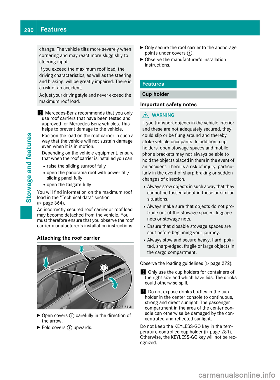
Attaching the roof carrier X
Open covers 0043carefully in the direction of
the arrow.
X Fold covers 0043upwards. X
Only secure the roof carrier to the anchorage
points under covers 0043.
X Observe the manufacturer's installation
instructions. Features
Cup holder
Important safety notes G
WARNING
If you transport objects in the vehicle interior and these are not adequately secured, they
could slip or be flung around and thereby
strike vehicle occupants. In addition, cup
holders, open stowage spaces and mobile
phone brackets may not always be able to
hold the objects placed in them in the event of an accident. There is a risk of injury, particu-
larly in the event of sharp braking or sudden
changes of direction.
R Always stow objects in such a way that they
cannot be tossed about in these or similar
situations.
R Always make sure that objects do not pro-
trude out of the stowage spaces, luggage
nets or stowage nets.
R Ensure that closable stowage spaces are
shut before beginning your journey.
R Always stow and secure heavy, hard, poin-
ted, sharp-edged, fragile or large objects in
the cargo compartment.
Observe the loading guidelines (Y page 272).
! Only use the cup holders for containers of
the right size and which have lids. The drinks
could otherwise spill.
! Do not expose drinks bottles in the cup
holder in the center console to continuous,
strong and direct sunlight. The passenger
compartment in the area of the center con-
sole can otherwise be damaged by the con-
centrated and reflected sunlight.
Do not keep the KEYLESS-GO key in the tem-
perature-controlled cup holder (Y page 281).
Otherwise, the KEYLESS-GO key will not be rec-
ognized. 280
FeaturesStowage and features
Page 283 of 370
The stowage compartments in the doors provide
space for bottles with a capacity of up to
34 fl. oz. (1.0 l).
The bottles are not secured or prevented from
tipping over. Therefore, do not place any open
drink containers in the stowage compartments.
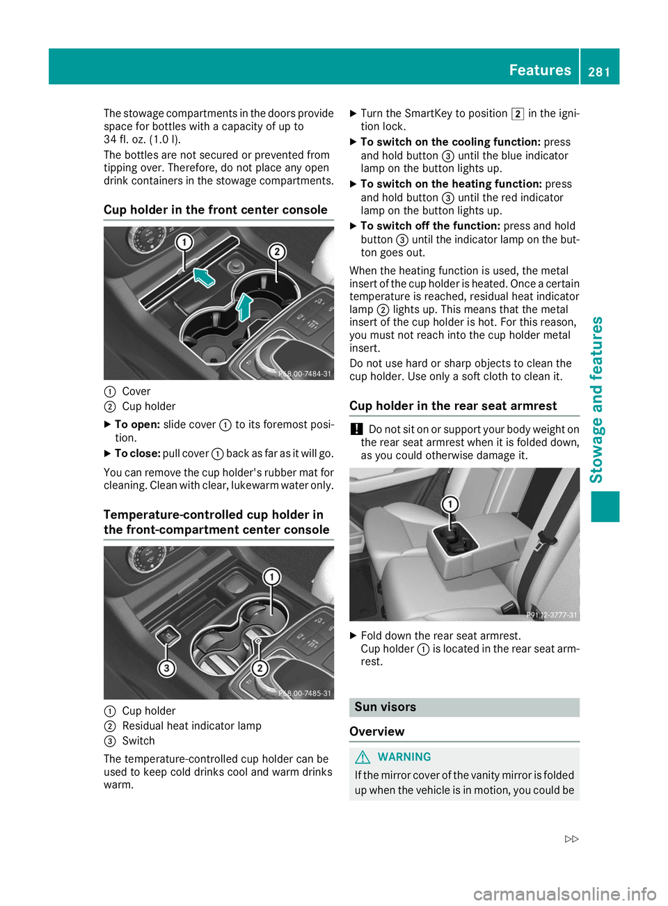
Cup holder in the front center console 0043
Cover
0044 Cup holder
X To open: slide cover 0043to its foremost posi-
tion.
X To close: pull cover 0043back as far as it will go.
You can remove the cup holder's rubber mat for
cleaning. Clean with clear, lukewarm water only.
Temperature-controlled cup holder in
the front-compartment center console 0043
Cup holder
0044 Residual heat indicator lamp
0087 Switch
The temperature-controlled cup holder can be
used to keep cold drinks cool and warm drinks
warm. X
Turn the SmartKey to position 0048in the igni-
tion lock.
X To switch on the cooling function: press
and hold button 0087until the blue indicator
lamp on the button lights up.
X To switch on the heating function: press
and hold button 0087until the red indicator
lamp on the button lights up.
X To switch off the function: press and hold
button 0087until the indicator lamp on the but-
ton goes out.
When the heating function is used, the metal
insert of the cup holder is heated. Once a certain temperature is reached, residual heat indicator
lamp 0044lights up. This means that the metal
insert of the cup holder is hot. For this reason,
you must not reach into the cup holder metal
insert.
Do not use hard or sharp objects to clean the
cup holder. Use only a soft cloth to clean it.
Cup holder in the rear seat armrest !
Do not sit on or support your body weight on
the rear seat armrest when it is folded down,
as you could otherwise damage it. X
Fold down the rear seat armrest.
Cup holder 0043is located in the rear seat arm-
rest. Sun visors
Overview G
WARNING
If the mirror cover of the vanity mirror is folded up when the vehicle is in motion, you could be Features
281Stowage and features
Z
Page 285 of 370
Vehicles without a Rear Seat Entertainment Sys-
tem have an ashtray in the center console in the rear compartment.
X To open: briefly press cover 0044at the top.
The ashtray opens.
X To remove the insert: push into recess0087
from the right.
Ashtray insert 0043slides out slightly to the
right.
X Lift insert 0043up and out.
X To re-install the insert: place insert0043into
the holder and press down on the right until it
engages. Cigarette lighter
G
WARNING
You can burn yourself if you touch the hot
heating element or the socket of the cigarette lighter.
In addition, flammable materials can ignite if:
R the hot cigarette lighter falls
R a child holds the hot cigarette lighter to
objects, for example
There is a risk of fire and injury.
Always hold the cigarette lighter by the knob.
Always make sure that the cigarette lighter is
out of reach of children. Never leave children unsupervised in the vehicle.
! The cigarette lighter in the center console in
the front compartment is not intended for
operating the tire inflation compressor. Your attention must always be focused on the
traffic conditions. Only use the cigarette lighter
when road and traffic conditions permit. X
Turn the SmartKey to position 0048in the igni-
tion lock (Y page 127).
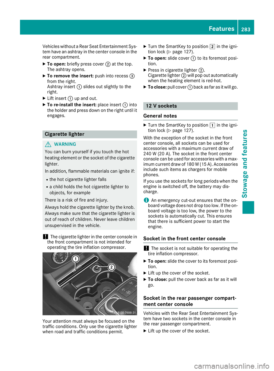
X To open: slide cover 0043to its foremost posi-
tion.
X Press in cigarette lighter 0044.
Cigarette lighter 0044will pop out automatically
when the heating element is red-hot.
X To close: pull cover 0043back as far as it will go. 12 V sockets
General notes X
Turn the SmartKey to position 0047in the igni-
tion lock (Y page 127).
With the exception of the socket in the front
center console, all sockets can be used for
accessories with a maximum current draw of
240 W (20 A). The socket in the front center
console can be used for accessories with a max-
imum current draw of 180 W(15 A). Accessories
include such items as chargers for mobile
phones.
If you use the sockets for long periods when the engine is switched off, the battery may dis-
charge.
i An emergency cut-out ensures that the on-
board voltage does not drop too low. If the on-
board voltage is too low, the power to the
sockets is automatically cut. This ensures
that there is sufficient power to start the
engine.
Socket in the front center console !
The socket is not suitable for operating the
tire inflation compressor.
X To open: slide the cover to its foremost posi-
tion.
X Lift up the cover of the socket.
X To close: pull the cover back as far as it will
go.
Socket in the rear passenger compart-
ment center console Vehicles with the Rear Seat Entertainment Sys-
tem have two sockets in the center console in
the rear passenger compartment.
X Lift up the cover of the socket. Features
283Stowage and features Z
Page 287 of 370
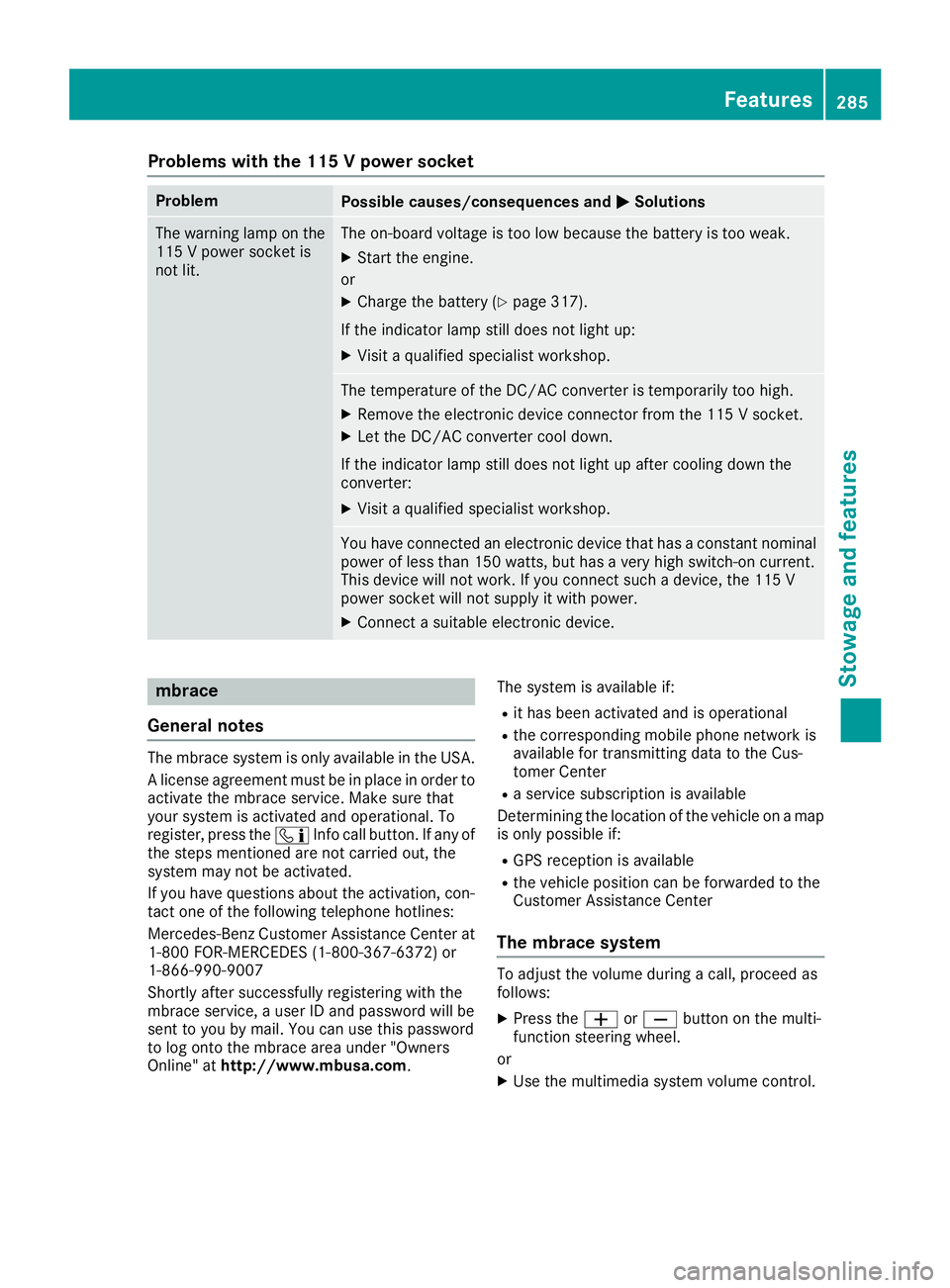
Problems with the 115 V power socket
Problem
Possible causes/consequences and
0050
0050Solutions The warning lamp on the
115 V power socket is
not lit. The on-board voltage is too low because the battery is too weak.
X Start the engine.
or X Charge the battery (Y page 317).
If the indicator lamp still does not light up: X Visit a qualified specialist workshop. The temperature of the DC/AC converter is temporarily too high.
X Remove the electronic device connector from the 115 V socket.
X Let the DC/AC converter cool down.
If the indicator lamp still does not light up after cooling down the
converter:
X Visit a qualified specialist workshop. You have connected an electronic device that has a constant nominal
power of less than 150 watts, but has a very high switch-on current.
This device will not work. If you connect such a device, the 115 V
power socket will not supply it with power.
X Connect a suitable electronic device. mbrace
General notes The mbrace system is only available in the USA.
A license agreement must be in place in order to
activate the mbrace service. Make sure that
your system is activated and operational. To
register, press the 00D9Info call button. If any of
the steps mentioned are not carried out, the
system may not be activated.
If you have questions about the activation, con- tact one of the following telephone hotlines:
Mercedes-Benz Customer Assistance Center at
1-800 FOR-MERCEDES (1-800-367-6372) or
1-866-990-9007
Shortly after successfully registering with the
mbrace service, a user ID and password will be
sent to you by mail. You can use this password
to log onto the mbrace area under "Owners
Online" at http://www.mbusa.com. The system is available if:
R it has been activated and is operational
R the corresponding mobile phone network is
available for transmitting data to the Cus-
tomer Center
R a service subscription is available
Determining the location of the vehicle on a map
is only possible if:
R GPS reception is available
R the vehicle position can be forwarded to the
Customer Assistance Center
The mbrace system To adjust the volume during a call, proceed as
follows:
X Press the 0081or0082 button on the multi-
function steering wheel.
or X Use the multimedia system volume control. Features
285Stowage and features Z
Page 288 of 370
The system offers various services, e.g.:
R Automatic and manual emergency call
R Roadside Assistance call
R Info call
You can find information and a description of all
available features under "Owners Online" at
http://www.mbusa.com.
System self-test After you have switched on the ignition, the sys-
tem carries out a self-diagnosis.
A malfunction in the system has been detected
if one of the following occurs:
R The indicator lamp in the SOS button does not
come on during the system self-test.
R The indicator lamp in the 0052Roadside
Assistance call button does not light up dur-
ing self-diagnosis of the system.
R The indicator lamp in the 00D9Info call button
does not light up during the system self-diag-
nosis.
R The indicator lamp in one or more of the fol-
lowing buttons continues to light up red after
the system self-diagnosis:
- SOS button
- 0052 Roadside Assistance call button
- 00D9 Info call button
R The Inoperative
Inoperative or theService Not Service Not
Activated
Activated message appears in the multi-
function display after the system self-diagno- sis.
If a malfunction is indicated as outlined above,
the system may not operate as expected. In the
event of an emergency, help will have to be
summoned by other means.
Have the system checked at the nearest author- ized Mercedes-Benz Center or call the following
telephone assistance services:
Mercedes-Benz Customer Assistance Center at
1-800-FOR-MERCedes (1-800-367-6372) or
1-866-990-9007. Emergency call Important safety notes
G
WARNING
It can be dangerous to remain in the vehicle,
even if you have pressed the SOS button in an emergency if:
R you see smoke inside or outside of the vehi-
cle, e.g. if there is a fire after an accident
R the vehicle is on a dangerous section of
road
R the vehicle is not visible or cannot easily be
seen by other road users, particularly whendark or in poor visibility conditions
There is a risk of an accident and injury.
Leave the vehicle immediately in this or simi-
lar situations as soon as it is safe to do so.
Move to a safe location along with other vehi-
cle occupants. In such situations, secure the
vehicle in accordance with national regula-
tions, e. g. with a warning triangle.
General notes
Observe the notes on system activation
(Y page 285).
The emergency call is triggered automatically if
an air bag is deployed or an Emergency Ten-
sioning Device is triggered. You cannot end an
automatically triggered emergency call yourself.
An emergency call can also be initiated man-
ually.
As soon as the emergency call has been initi-
ated, the indicator lamp in the SOS button
flashes. The Connecting Call Connecting Call message
appears in the multifunction display.
The audio output is muted.
Once the connection has been made, the Call Call
Connected
Connected message appears in the multifunc-
tion display.
All important information on the emergency is
transmitted, for example:
R Current location of the vehicle (as determined
by the GPS system)
R Vehicle identification number
R Information on the severity of the accident
Shortly after the emergency call has been initi-
ated, a voice connection is automatically estab- 286
FeaturesStowage and features
Page 294 of 370
The data you receive contains the following
information:
R the location where the speed limit was excee-
ded
R the time at which the speed limit was excee-
ded
R the selected speed limit which was exceeded
Geo fencing Geo fencing allows you to select areas which the
vehicle should not enter or leave. You will be
informed if the vehicle crosses the boundaries
of the selected areas. You can select the way in which you receive this information beforehand.
Possible options include text message, e-mail or an automated call.
The area can be determined as either a circle or
a polygon with a maximum of ten corners. You
can specify up to ten areas simultaneously. Dif- ferent settings are possible for each area.
These settings can be called up under "Owners
Online" at http://www.mbusa.com.
Alternatively, you can also trigger an Info call
and notify the customer service representative
that you wish to activate geo-fencing.
Currently inactive areas can be activated by text
message.
Triggering the vehicle alarm With this function, you can trigger the vehicle's
panic alarm via text message. An alarm sounds
and the exterior lighting flashes. Depending on
the setting, the panic alarm lasts five or ten sec-
onds. Afterwards, the alarm switches off. Garage door opener
General notes The HomeLink
®
garage door opener integrated
in the rear-view mirror allows you to operate up to three different door and gate systems.
Use the integrated garage door opener only on
garage doors that:
R they are equipped with a safety stop and
reverse feature
R they conform to the current U.S. safety stand-
ards When it has been programmed, the integrated
garage door opener in the rear-view mirror will
assume the function of the garage door sys-
tem's remote control. Please also read the oper-
ating instructions for the garage door system.
When programming a garage door opener, park the vehicle outside the garage. Do not leave the
engine running while programming.
Certain garage door drives are incompatible
with the integrated garage door opener. If you
have difficulty programing the integrated garage
door opener, contact a Mercedes-Benz Service
Center.
Alternatively, you can call the following tele-
phone assistance services:
R USA: Mercedes-Benz Customer Assistance
Center at 1-800-FOR-MERCedes
R Canada: Customer Service at
1-800-387-0100
R HomeLink ®
hotline 1-800-355-3515 (free of
charge)
More information on HomeLink ®
and/or com-
patible products is also available on the Internet
at http://www.homelink.com.
Notes on the declaration of conformity
(Y page 29).
USA: FCC ID: CB2HMIHL4
Canada: IC: 279B-HMIHL4
Important safety notes G
WARNING
When you operate or program the door with
the integrated garage door opener, persons in the range of movement of the door may
become trapped or be struck by the door.
There is a risk of injury.
When using the integrated garage door
opener, always make sure that nobody is
within the range of movement of the door. G
DANGER
Combustion engines emit poisonous exhaust
gases such as carbon monoxide. Inhaling
these exhaust gases is hazardous to health
and can result in poisoning. There is a risk of
fatal injury. Therefore, never leave the engine running an enclosed space without adequate
ventilation. 292
FeaturesStowage and features
Page 297 of 370
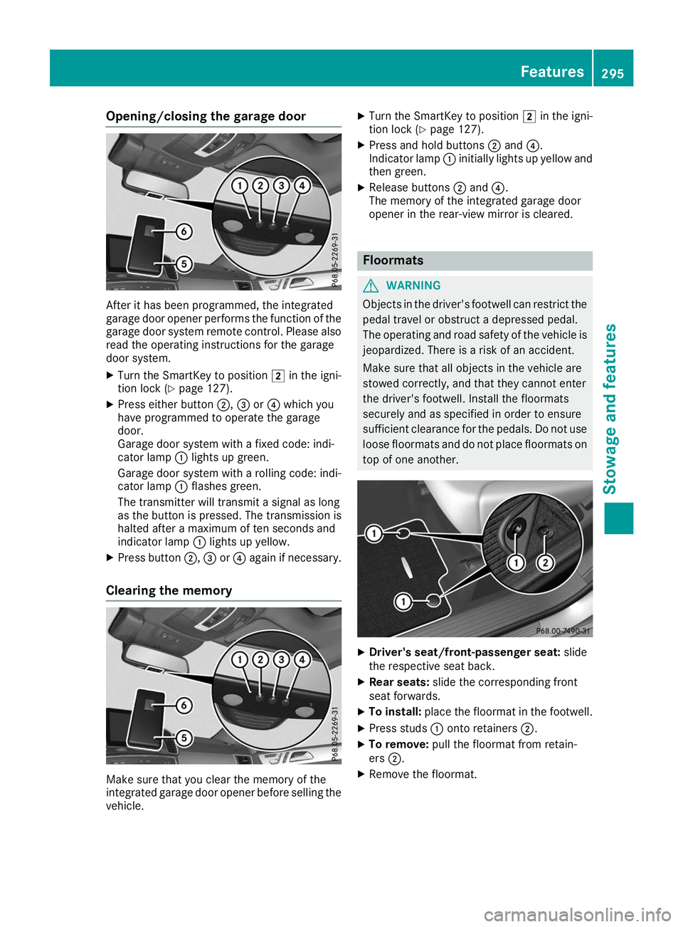
Opening/closing the garage door
After it has been programmed, the integrated
garage door opener performs the function of the
garage door system remote control. Please also
read the operating instructions for the garage
door system.
X Turn the SmartKey to position 0048in the igni-
tion lock (Y page 127).
X Press either button 0044,0087or0085 which you
have programmed to operate the garage
door.
Garage door system with a fixed code: indi-
cator lamp 0043lights up green.
Garage door system with a rolling code: indi-
cator lamp 0043flashes green.
The transmitter will transmit a signal as long
as the button is pressed. The transmission is
halted after a maximum of ten seconds and
indicator lamp 0043lights up yellow.
X Press button 0044,0087or0085 again if necessary.
Clearing the memory Make sure that you clear the memory of the
integrated garage door opener before selling the vehicle. X
Turn the SmartKey to position 0048in the igni-
tion lock (Y page 127).
X Press and hold buttons 0044and 0085.
Indicator lamp 0043initially lights up yellow and
then green.
X Release buttons 0044and 0085.
The memory of the integrated garage door
opener in the rear-view mirror is cleared. Floormats
G
WARNING
Objects in the driver's footwell can restrict the pedal travel or obstruct a depressed pedal.
The operating and road safety of the vehicle is
jeopardized. There is a risk of an accident.
Make sure that all objects in the vehicle are
stowed correctly, and that they cannot enter
the driver's footwell. Install the floormats
securely and as specified in order to ensure
sufficient clearance for the pedals. Do not use loose floormats and do not place floormats on
top of one another. X
Driver's seat/front-passenger seat: slide
the respective seat back.
X Rear seats: slide the corresponding front
seat forwards.
X To install: place the floormat in the footwell.
X Press studs 0043onto retainers 0044.
X To remove: pull the floormat from retain-
ers 0044.
X Remove the floormat. Features
295Stowage and features Z
Page 299 of 370
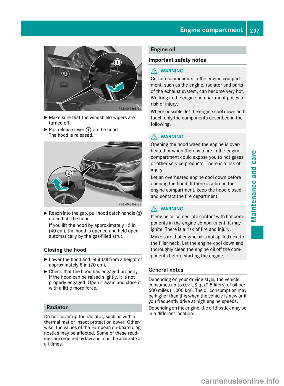
X
Make sure that the windshield wipers are
turned off.
X Pull release lever 0043on the hood.
The hood is released. X
Reach into the gap, pull hood catch handle 0044
up and lift the hood.
If you lift the hood by approximately 15 in
(40 cm), the hood is opened and held open
automatically by the gas-filled strut.
Closing the hood X
Lower the hood and let it fall from a height of
approximately 8 in (20 cm).
X Check that the hood has engaged properly.
If the hood can be raised slightly, it is not
properly engaged. Open it again and close it
with a little more force. Radiator
Do not cover up the radiator, such as with a
thermal mat or insect protection cover. Other-
wise, the values of the European on-board diag- nostics may be affected. Some of these read-
ings are required by law and must be accurate at all times. Engine oil
Important safety notes G
WARNING
Certain components in the engine compart-
ment, such as the engine, radiator and parts
of the exhaust system, can become very hot.
Working in the engine compartment poses a
risk of injury.
Where possible, let the engine cool down and touch only the components described in the
following. G
WARNING
Opening the hood when the engine is over-
heated or when there is a fire in the engine
compartment could expose you to hot gases
or other service products. There is a risk of
injury.
Let an overheated engine cool down before
opening the hood. If there is a fire in the
engine compartment, keep the hood closed
and contact the fire department. G
WARNING
If engine oil comes into contact with hot com- ponents in the engine compartment, it may
ignite. There is a risk of fire and injury.
Make sure that engine oil is not spilled next to
the filler neck. Let the engine cool down and
thoroughly clean the engine oil off the com-
ponents before starting the engine.
General notes Depending on your driving style, the vehicle
consumes up to 0.9 US qt (0.8 liters) of oil per
600 miles (1,000 km). The oil consumption may
be higher than this when the vehicle is new or if
you frequently drive at high engine speeds.
Depending on the engine, the oil dipstick may be in a different location. Engine compartment
297Maintenance and care Z