2019 MERCEDES-BENZ GLC COUPE fuse box
[x] Cancel search: fuse boxPage 501 of 657
#
Screw intheto wing eyeclockwise as far as it
will go and tighten.
Ve hicles with a trailer hitch: vehicles with a
trailer hitch do not ha veare ar brac ketfo rthe
to wing eye. Fasten theto w bar tothe trailer
hitch.
% Make sure that co ver1 engages in the
bumper when youre mo vetheto wing eye.
* NO
TEDama gedue toincor rect use of
th eto wing eye When a
towing eye is used toreco ver a vehi‐
cle, theve hicle may be damaged in the proc‐
ess. #
Only use theto wing eyeto to waw ay or
to w start theve hicle. To
w starting theve hicle (eme rgency engine
st art) Ve
hicles with automatic transmission
* NO
TEDama getothe automatic trans‐
mission due to tow-starting The automatic transmission may be damaged
in the process of tow- starting vehicles with
automatic transmission. #
Vehicles with automatic transmission
must not be tow- star ted. #
Vehicles with automatic transmission must
not be tow- star ted. Electrical fuses
Note
s on electrical fuses &
WARNING Risk of accident and inju ry
due to ov erloaded lines
If yo u manipulate or bridge a faulty fuse or if
yo ure place it with a fuse with a higher amperage,
the electric line could be overloa‐
ded.
This could result in a fire. #
Alw aysre place faulty fuses with speci‐
fi ed new fuses conta iningthe cor rect
amperage. *
NO
TEDama gedue toincor rect fuses Electrical components or sy
stems may be
damaged byincor rect fuses, or their func‐
tionality may be significant lyimpaired. #
Only use fuses that ha vebeen appr oved
by Mercedes-Benz and which ha vethe
cor rect fuse rating. Blown fuses mu
stbe replaced with fuses of the
same rating, which you can recognise bythe col‐
our and fuse rating. The fuse ratings and fu rther
information tobe obser ved are lis ted in the fuse
assignment diagram.
Fu se assignment diag ram: onthe fuse box in
th e load compartment (/ page 500).498
Breakdown assis tance
Page 502 of 657
*
NO
TEDama geor malfunctions caused
by moisture Moisture may cause dama
getothe electrical
sy stem or cause it tomalfunction. #
When the fuse box is open, make sure
th at no moisture can enter the fuse
box. #
When closing the fuse box, make sure
th at the seal of the lid is positioned cor‐
re ctly on the fuse box. If
th e newly inser ted fuse also blo ws, ha vethe
cause traced and rectified at a qualified special‐
ist workshop.
Ensure thefo llowing before replacing a fuse:
R The vehicle is secured against rolling away.
R All electrical consumers are switched off.
R The ignition is switched off.
The electrical fuses are located in various fuse
bo xes:
R Fuse box in the engine compartment on the
driver's side (/ page 499) R
Fuse box on the driver's side of the cockpit
(/ page 500)
R Fuse box in the front passenger foot we ll
(/ page 500)
R Fuse box in the load compartment on the
ri ght-hand side of theve hicle, when vie wed
in the direction of tra vel (/ page 500) Opening and closing
the fuse box in the
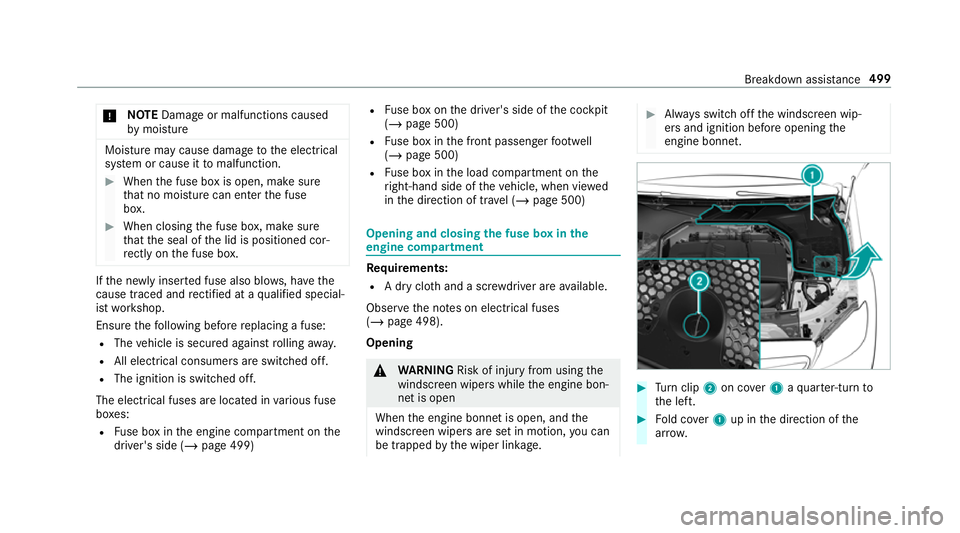
engine compa rtment Re
quirements:
R A dry clo thand a sc rewdriver are available.
Obse rveth e no tes on electrical fuses
(/ page 498).
Opening &
WARNING Risk of inju ryfrom using the
windscreen wipers while the engine bon‐
net is open
When the engine bonn etis open, and the
windscreen wipers are set in motion, you can
be trapped bythe wiper linkage. #
Alw ays switch off the windscreen wip‐
ers and ignition before opening the
engine bonn et. #
Turn clip 2on co ver1 aqu arter-turn to
th e left. #
Fold co ver1 up in the direction of the
ar row. Breakdown assis
tance 499
Page 503 of 657
#
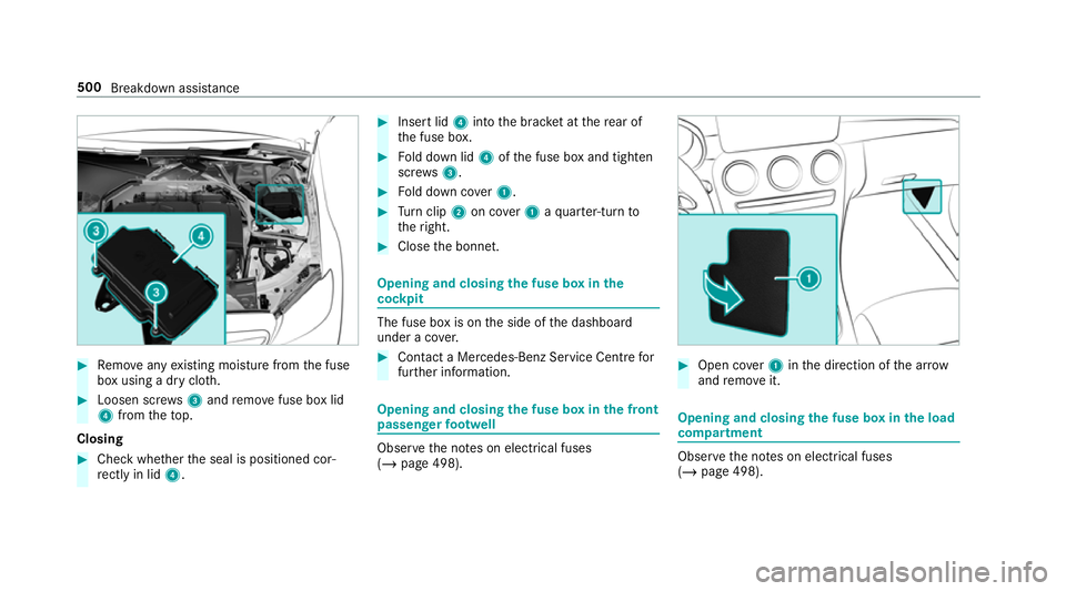
Remo veany existing moisture from the fuse
box using a dry clo th.#
Loosen scr ews3 and remo vefuse box lid
4 from theto p.
Closing #
Check whe ther the seal is positioned cor‐
re ctly in lid 4. #
Insert lid 4into the brac ket at there ar of
th e fuse box. #
Fold down lid 4ofthe fuse box and tighten
scr ews3. #
Fold down co ver1. #
Turn clip 2on co ver1 aqu arter-turn to
th eright. #
Close the bonn et. Opening and closing
the fuse box in the
cockpit The fuse box is on
the side of the dashboard
under a co ver. #
Con tact a Mercedes-Benz Service Centre for
fur ther information. Opening and closing
the fuse box in the front
passenger foot we ll Obser
vethe no tes on electrical fuses
(/ page 498). #
Open co ver1 inthe direction of the ar row
and remo veit. Opening and closing
the fuse box in the load
compa rtment Obse
rveth e no tes on electrical fuses
(/ page 498). 500
Breakdown assis tance
Page 504 of 657
#
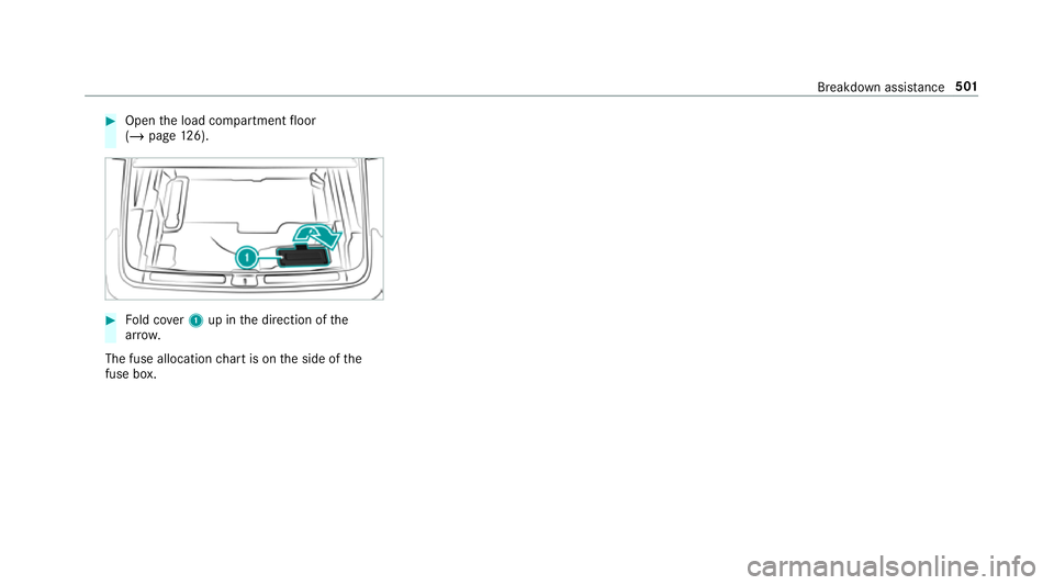
Open the load compartment floor
(/ page 126). #
Fold co ver1 up in the direction of the
ar row.
The fuse allocation chart is on the side of the
fuse box. Breakdown assi
stance 501
Page 628 of 657
Fu
nction seat
see Door cont rol panel
Fu ses ........................................................ 498
Before replacing a fuse ........................ 498
Fu se assignment diagram ...................4 98
Fu se box in the engine compartment .. 499
Fu se box in the front passenger foot‐
we ll ...................................................... 500
Fu se box in the load compartment ...... 500
Fu se box on the dashboard ................. 500
No tes .................................................. 498 G
Garage door opener Cleari ngthe memory ........................... 194
Opening or closing the door ................1 94
Programming buttons .......................... 19 2
Ra dio equipment appr oval numbers .... 19 5
Re solving problems ............................. 19 3
Synchronising thero lling code ............ 19 3
Gearshift recommendation ....................183
Genera l operating permit number
(EU) .......................................................... .524
Genuine parts ............................................ 20 Glide mode
............................................... 183
Global sear ch
Fu nction .............................................. 329
Overview ............................................. 328
Glo vecompa rtment
Locking/unlo cking .............................. .115 H
Handbrake see Electric parking brake
Handling characteristics (unusual) ....... 502
HANDS-FREE ACCESS ................................ 86
Haza rdwa rning lights ............................ .140
HD prog rammes
see CI+ module
Head restra int
Fr ont (adjusting mechanically) .............1 04
Re ar (adjusting) .................................. .105
Re ar (fitting/removing) ........................ 106
Head-up display ....................................... 281
Ad justing display elements (on-board
compu ter) ............................................ 281 Ad
justing the brightness (on-board
computer) ............................................ 281
Fu nction .............................................. 282
Menu (on-board compu ter) .................. 281
Setting the position (on-board com‐
puter) ................................................... 281
Switching on/off ................................. 283
Headla mpflasher ................................... .139
Heating see Clima tecontrol
High beam Adaptive Highbeam Assist .................. .142
Ad aptive Highbeam Assist Plus .......... .143
Switching on/off ................................. 13 9
High-pressure cleaner (care) ..................470
Hill Start Assist ....................................... 228
HOLD function ......................................... 228
Fu nction/no tes ................................... 228
Switching on/off ................................. 229
Home screen (media display) Overview ............................................. 306
Hooking the luggage net .........................123 Index
625