2019 MERCEDES-BENZ GLC COUPE ABS
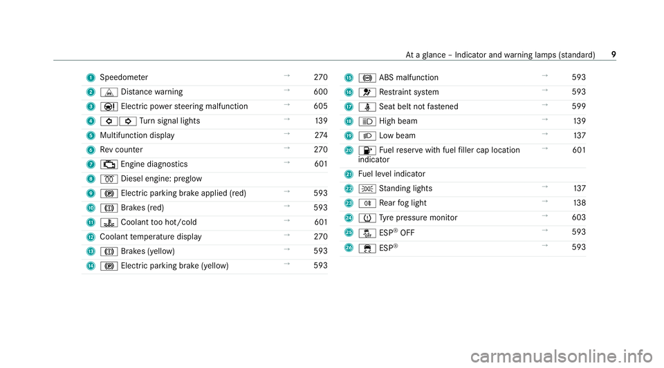
[x] Cancel search: ABSPage 12 of 657

1
Speedom eter →
270
2 L Distance warning →
600
3 Ð Electric po werst eering malfunction →
605
4 #! Turn signal lights →
13 9
5 Multifunction display →
274
6 Rev counter →
270
7 ; Engine diagnostics →
601
8 % Diesel engine: preglow
9 ! Electric pa rking brake applied (red) →
593
A J Brakes (red) →
593
B ? Coolant too hot/cold →
601
C Coolant temp erature display →
270
D J Brakes (yell ow) →
593
E ! Electric parking brake (yell ow)→
593 F
! ABS malfunction →
593
G 6 Restra int sy stem →
593
H ü Seat belt not fastened →
599
I K High beam →
13 9
J L Low beam →
137
K 8 Fuelreser vewith fuel filler cap location
indicator →
601
L Fuel le vel indicator
M T Standing lights →
137
N R Rear fog light →
13 8
O h Tyre pressure monitor →
603
P å ESP®
OFF →
593
Q ÷ ESP®
→
593 At
aglance – Indicator and warning lamps (s tanda rd) 9
Page 14 of 657

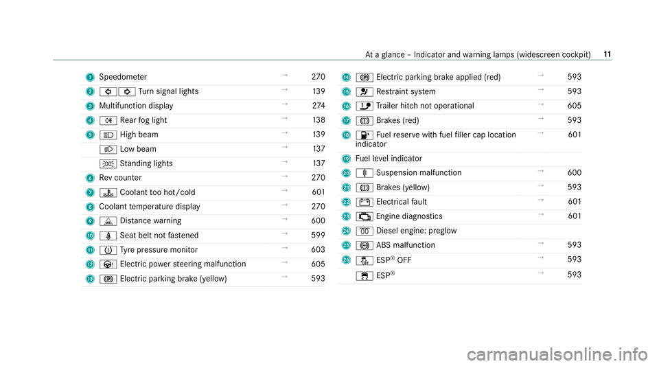
1
Speedom eter →
270
2 #! Turn signal lights →
13 9
3 Multifunction display →
274
4 R Rear fog light →
13 8
5 K High beam →
13 9
L Low beam →
137
T Standing lights →
137
6 Rev counter →
270
7 ? Coolant too hot/cold →
601
8 Coolant temp erature display →
270
9 L Distance warning →
600
A ü Seat belt not fastened →
599
B h Tyre pressure monitor →
603
C Ù Electric po werst eering malfunction →
605
D ! Electric pa rking brake (yellow) →
593 E
! Electric parking brake applied (red) →
593
F 6 Restra int sy stem →
593
G ï Trailer hit chnot operational →
605
H J Brakes (red) →
593
I 8 Fuelreser vewith fuel filler cap location
indicator →
601
J Fuel le vel indicator
K ä Suspension malfunction →
600
L J Brakes (yellow) →
593
M # Electrical fault →
601
N ; Engine diagnostics →
601
O % Diesel engine: preglow
P ! ABS malfunction →
593
Q å ESP®
OFF →
593
÷ ESP®
→
593 At
aglance – Indicator and warning lamps (widesc reen cockpit) 11
Page 25 of 657

Obser
vethe "On-board electronics" section in
"Technical data". &
WARNING Risk offire due toflammable
materials on hot parts of theex haust
sy stem
Flammable material such as lea ves, grass or
twigs may ignite if they come into contact
wi th hot parts of theex haust sy stem. #
When driving on unpa vedro ads or off-
ro ad, regular lych eck theve hicle under‐
side. #
Remo vetrapped plants or other flam‐
mable material, in particular. #
Ifth ere is damage, consult a qualified
specialist workshop immediately. *
NO
TEDama getotheve hicle In
thefo llowing situations, in particular, there
is a risk of damage totheve hicle:
R theve hicle becomes grounded, e.g. on a
high kerb or an unpa vedro ad R
theve hicle is driven toofast over an
obs tacle, e.g. a kerb, speed bump or pot‐
hole
R a heavy object strike sth e underbody or
ch assis components
In situations such as this, the body, the
underbody, chassis components, wheels or
tyres could be damaged without the damage
being visible. Components damaged in this
wa y can unexpec tedly fail or, in the case of
an accident, may not absorb the loads that
arise as intended.
If th e underbody panelling is damaged, flam‐
mable materials such as lea ves, grass or
twigs can collect between the underbody and
th e underbody panelling. These materials
may ignite if they come into contact wi thhot
parts on theex haust sy stem. #
Have theve hicle checked and repaired
immediately at a qualified specialist
wo rkshop.
or #
If driving saf ety is impaired while con‐
tinuing your journe y,pull over and stop
th eve hicle immediately in accordance
with the traf fic conditions, and contact
a qu alified specialist workshop. Ve
hicles with a 48 V on-board electrical sys‐
te m (EQ Boo sttech nology) &
DANG ER Risk of fata l injury bytouching
damaged high-voltage co mponents
Ve hicles with a 48 V on-board electrical sys‐
te m contain individual high-voltage compo‐
nents. These high-voltage components are
under high voltage.
If yo u modify co mponent parts of these high-
vo ltage components or touch damaged com‐
ponent parts, you may be electrocuted.
High voltage components may be damaged
in an accident, although the damage may not
be visible. #
Never per form modifications tocompo‐
nent pa rts of high-voltage components. 22
General no tes
Page 69 of 657

We
ight categor yL eft/rightrear seat
Centrerear seat 1
Catego ryII:15 to25 kg U, LU , L
Category III: 22to36 kg U, LU , L
U Suitable forch ild restrai nt sy stems of the "Universal" category in this we ight categor y.
L Suitable for semi-universal child restrai nt sy stems according totheta ble in "Recommended child restrai nt sy stems", or if theve hicle and the seat are lis ted in the
ch ild restrai nt sy stem manufacturer's vehicle model list. Fr
ont passenger seat – NotesNote
s onchild restra int sy stems on the front passenger seat
R If it is absolutely necessary foryo uto fit a child restra int sy stem tothe front passenger seat, be sure toobser vethe information on child restra int
sy stems on the front passenger seat (/ page 70).
Obser vethe specific instructions forth ere ar wa rd-facing and forw ard-facing child restra int sy stems. If the front passenger seat is occupied, ensure,
bo th before and during the journe y,that thest atus of the front passenger airbag is cor rect forth e cur rent situation (/ page 45). 66
Occupant saf ety
Page 73 of 657

Note
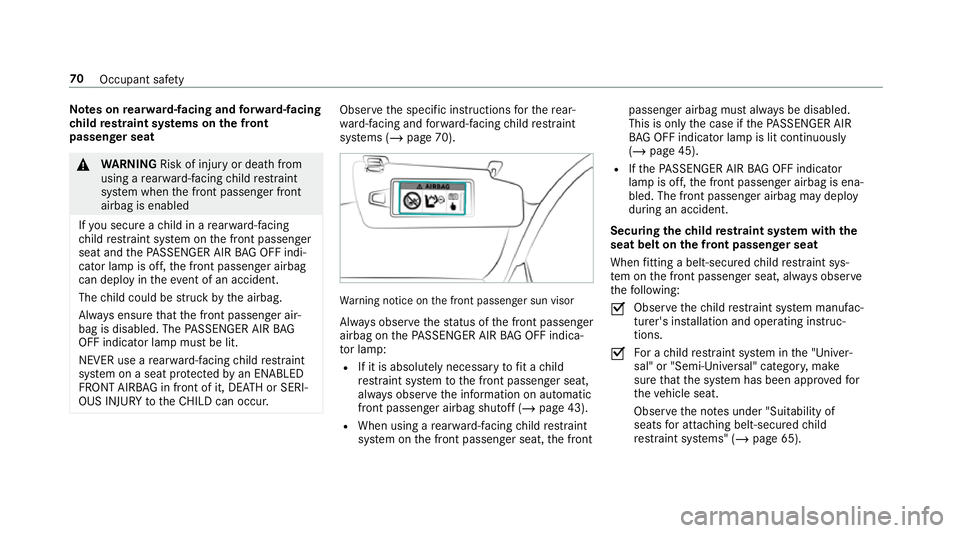
s onrear wa rd-facing and forw ard-facing
ch ild restra int sy stems on the front
passenger seat &
WARNING Risk of inju ryor death from
using a rear wa rd-facing child restra int
sy stem when the front passenger front
airbag is enabled
If yo u secure a child in a rear wa rd-facing
ch ild restra int sy stem on the front passenger
seat and thePA SSENGER AIR BAG OFF indi‐
cator lamp is off, the front passenger airbag
can deploy in theev ent of an accident.
The child could be stru ck bythe airbag.
Alw ays ensure that the front passenger air‐
bag is disabled. The PASSENGER AIR BAG
OFF indicator lamp must be lit.
NEVER use a rear wa rd-facing child restra int
sy stem on a seat pr otected byan ENABLED
FRONT AIRB AGin front of it, DE ATH or SERI‐
OUS INJU RYtotheCH ILD can occur. Obser
vethe specific instructions forth ere ar‐
wa rd-facing and forw ard-facing child restra int
sy stems (/ page 70). Wa
rning notice on the front passenger sun visor
Alw ays obser vethest atus of the front passenger
airbag on thePA SSENGER AIR BAG OFF indica‐
to r lamp:
R If it is absolutely necessary tofit a child
re stra int sy stem tothe front passenger seat,
alw ays obser vethe information on automatic
front passenger airbag shutoff (/ page 43).
R When using a rear wa rd-facing child restra int
sy stem on the front passenger seat, the front passenger airbag must alw
ays be disabled.
This is only the case if thePA SSENGER AIR
BA G OFF indicator lamp is lit continuously
(/ page 45).
R Ifth ePA SSENGER AIR BAG OFF indicator
lamp is off, the front passenger airbag is ena‐
bled. The front passenger airbag may deploy
during an accident.
Securing thech ild restra int sy stem with the
seat belt on the front passenger seat
When fitting a belt-secu redch ild restra int sys‐
te m on the front passenger seat, alw ays obser ve
th efo llowing:
O Obser
vethech ild restra int sy stem manufac‐
turer's ins tallation and operating instruc‐
tions.
O Fo
r a child restra int sy stem in the "Univer‐
sal" or "Semi-Universal" categor y,make
sure that the sy stem has been appr ovedfor
th eve hicle seat.
Obser vethe no tes under "Suitability of
seats for attaching belt-secu redch ild
re stra int sy stems" (/ page 65). 70
Occupant saf ety
Page 203 of 657

in front of, behind or next
totheve hicle (depend‐
ing on theve hicle's equipment).
Depending on theve hicle's equipment, thera dar
sensors are integrated behind the bumpers
and/or behind the Mercedes star. The ultrasonic
sensors are located in the front and rear bump‐
ers. Keep these parts free of dirt, ice and slush
(/ page 475). The se nsors mustnot be cov‐
ered, forex ample bycycle rack s, ove rhanging
loads, sticke rs,fo il or foils toprotect against
st one chipping. Additional license plate brac kets
can li kewise impair the function of the ultrasonic
sensors. In theev ent of damage tothe bumpers
or radiator grille, or following a collision impact‐
ing the bumpers or radiator grille, ha vethe func‐
tion of the sensors checked at a qualified spe‐
cialist workshop. If the sensors are damaged,
some driving sy stems and driving saf ety sy stems
may no longer function proper ly. Overview of driving sy
stems and driving
saf ety sy stems In
this section, you will find information about
th efo llowing driving sy stems and driving saf ety
sy stems:
R 360° Camera (/ page243)
R ABS ( Anti-lo ckBra king System)
(/ page 201)
R Active Dis tance Assi stDISTRONIC
(/ page 216)
R Adaptive Brake Lights (/ page212)
R AIR BODY CONTROL (/ page 230)
R Active Brake Assi st (/ page 206)
R Active Lane Keeping Assist (/ page 260)
R ATTENTION ASSIST (/ page 253)
R BAS (Bra keAssist System) (/ page 201)
R Hill Start Assist (/ page 228)
R DYNA MIC BODY CONTROL (/ page 230)
R EBD ( Electronic Brakeforc eDistribution)
(/ page 206) R
ESP ®
(Elect ronic Stability Program)
(/ page 201)
R ESP ®
Crosswind Assist (/ page 205)
R ESP ®
trailer stabilisation (/ page 206)
R Active Speed Limit Assi st (/ page 220)
R HOLD function (/ page 228)
R STEER CONTROL (/ page 206)
R Active Steering Assist with rescue lane func‐
tion (/ page 222)
R Limiter (/ page213)
R Active Emergency Stop Assist (/ page 226)
R Active Parking Assist (/ page247)
R Parking Assist PARKTRONIC (/ page 233)
R Reversing camera (/ page240)
R Active Lane Change Assi st (/ page 224)
R Cruise control (/ page212)
R Blind Spot Assi stand Active Blind Spot Assi st
with exitwa rning (/ page 257)
R Traf fic Sign Assi st (/ page 255) 200
Driving and parking
Page 204 of 657

Fu
nction of ABS The Anti-lock Brake Sy
stem (ABS) regulates the
brake pressure in critical driving situations:
R During braking, e.g. at full brake application
or insuf ficient tyre traction, the wheels are
pr eve nted from lo cking.
R Vehicle steerability while braking is ensured.
If ABS inter venes when braking, you will feel a
pulsing in the brake pedal. The pulsating brake
pedal can be an indication of hazardous road
conditions and can ser veas a reminder totake
ex tra care while driving.
Sy stem limits
R ABS is active from speeds of appr ox.
8 km/h.
R ABS may be impai red or may not function if a
malfunction has occur red and theye l‐
low ! ABSwarning lamp lights up contin‐
uously in the instrument clus ter af terthe
engine is star ted. Fu
nction of BAS (Brake Assist Sy stem) &
WARNING Risk of an accident caused by
a malfunction in BAS (Brake Assi stSys‐
te m)
If BA S is malfunctioning, the braking dis tance
in an emergency braking situation is
increased. #
Dep ress the brake pedal with full force
in emer gency braking situations. ABS
pr eve nts the wheels from locking. BA
S suppo rts yo ur eme rgency braking situation
with additional brake forc e.
If yo u depress the brake pedal quickl y,BA S is
acti vated:
R BAS au tomatical lyboosts the brake pres‐
sure.
R BAS can sho rten the braking dis tance.
R ABS pr events the wheels from locking.
The brakes will function as usual once you
re lease the brake pedal. BAS is deactivated. Fu
nction of ESP ®
(Electronic Stability Pro‐
gr am) &
WARNING Risk of skidding if ESP ®
is
malfunctioning
If ESP ®
is malfunctioning, ESP ®
cannot car ry
out vehicle stabilisation. In addition, other
driving saf ety sy stems are switched off. #
Drive on carefull y. #
Have ESP ®
ch ecked at a qualified spe‐
cialist workshop. &
WARNING Risk of skidding if ESP ®
is
deactivated
If yo u deactivate ESP ®
, ESP ®
cannot car ry
out vehicle stabilisation. #
ESP ®
should on lybe deactivated in the
fo llowing situations. Mercedes‑AMG
vehicles: be sure toobser ve
th e no tes in the Supplement. Otherwise, you
may failto recognise dangers. Driving and pa
rking 201
Page 404 of 657

Connecting a mobile phone (au
thorisation
using Secure Simple Pairing) #
Select a mobile phone. #
A code is displa yed in the multimedia sy stem
and on the mobile phone. #
Ifth e codes match: confirm the code on
th e mobile phone.
% For older mobile phone models, enter a one
to sixteen-digit number code on the mobile
phone and on the multimedia sy stem for
authorisation.
% Upto15 mobile phones can be auth orised
on the multimedia sy stem.
Auth orised mobile phones are reconnected
au tomatical ly.
% The connected mobile phone can also be
used as Blue tooth®
audio equipment
(/ page 441).
Connecting a second mobile phone (two
phone mode)
Requ irements:
R Atleast one mobile phone is already connec‐
te dto the multimedia sy stem via Blue tooth®
. Multimedia sy
stem:
4 © 5
Phone #
Select í. #
Select Connect new device. #
Select the mobile phone. #
Select
The selected mobile phone is connected to
th e multimedia sy stem.
Fu nctions of the mobile phone in two phone
mode
Fu nctions overview Mobile phone in
the
fo re gr ound Mobile phone in
the
bac kground
Fu llra nge of func‐
tions Incoming calls and
messa ges Inter
changing mobile phones (two phone
mode)
Multimedia sy stem:
4 © 5
Phone
Bo th mobile phones are shown individually in
sepa rate tabs. #
Select theta b with the desired mobile
phone.
The mobile phone in the selected tab is the
mobile phone in thefo re ground.
Wi th th eexc eption of telephone settings, the
submenus in thete lephone menu relate to
th e mobile phone in thefo re ground. In the
te lephone settings, settings can be made for
bo th mobile phones.
Changing the function of a mobile phone
Multimedia sy stem:
4 © 5
Phone
Ac tivating a function #
Select í. MBUX multimedia sy
stem 401