2019 MERCEDES-BENZ GLC COUPE wheel
[x] Cancel search: wheelPage 228 of 657

R
The driven speed is between 80 km/h and
18 0 km/h.
R Active Lane Change Assi stis switched on in
th e multimedia sy stem.
R Active Steering Assist is switched on and
active. If no
vehicle is de tected in the adjacent lane and
a lane change is permit ted, the lane change
begins af terth e driver has activated the turn sig‐
nal indicator. This is shown tothe driver with a
green ar row 2 next tothesteering wheel sym‐
bol. The Lane change to the left message also
appears, forex ample. If Active Lane Change
Assi sthas been activated with the turn signal indicator but a lane
change is not immediately
possible, a gr eyarrow 1appears next tothe
st eering wheel symbol, which remains green.
When the lane change assis tance starts, the turn
signal indicator is automatically activated along
with the display in the multifunction displa y.
If th e assis tance graphic is shown when chang‐
ing lanes, the lane change display appears with
an additional ar rowpointing towa rdsth e adja‐
cent lane (/ page 226).
If a lane change is not possible, the ar row fades
out af ter a few seconds and a new lane change
must be initiated. An immediate lane change is
on lypossible on mo torw ay sections without
speed limits.
If th e sy stem is impaired, Active Lane Change
Assi stmay be cancelled. If it is cancelled, the
Lane change cancelled message appears inthe
multifunction display and a warning tone sounds. &
WARNING Risk of accident from chang‐
ing lane toan occupied adjacent lane
Lane Chan geAssi stcannot al ways detect
clearly if the adjacent lane is free. The lane
change might be initiated although
th e adjacent lane is not free. #
Before changing lanes, make sure that
th e neighbouring lane is free and there
is no danger to otherroad users. #
Monitor the lane change. &
WARNING Risk of accident if Lane
Change Assi stunexpectedly stops func‐
tioning
If th e sy stem limitations for Lane Change
Assist ha vebeen reached, there is no guar‐
antee that the sy stem will remain active.
Lane Change Assist cannot then assist you
by applying steering torques. #
Alw ays monitor the lane change and
ke ep your hands on thesteering wheel.
Obser vethe tra ffic conditions and steer
and/or brake if necessar y. Driving and pa
rking 225
Page 229 of 657
Sy
stem limits
The sy stem limitations of Active Steering Assist
apply toActive Lane Change Assi st
( / page 222).
The sy stem may also be impaired or may not
function in thefo llowing situations:
R The sensors in there ar bumper are dirty,
damaged or co vered, for ins tance by a
st icke r or ice and sno w.
R The exterior lighting is malfunctioning.
Ac tivating/deactivating Active Lane Change
Assi st
Multimedia sy stem:
4 © 5
Settings 5
Assistance
5 Active Lane Change Assist #
Activate or deacti vate the function.
Fu nction of Active Eme rgency Stop Assist
If th e driver continually ignores the visual or
acoustic warning toput their hands on thesteer‐
ing wheel, theBeginning emergency stop mes‐
sage appears in the multifunction displa y.Ifthe
driver still does not respond, Active Dis tance Assi
stDISTRONIC reduces the speed. The vehi‐
cle is decelerated in stages toast andstill.
Depending on the count ry, at speeds below
60 km/h the hazard warning lights switch on
automaticall y.
When theve hicle is stationar y,thefo llowing
actions are car ried out:
R theve hicle is secured with the electric park‐
ing brake
R Active Dis tance Assi stDISTRONIC is ended
R theve hicle is unloc ked
R if possible, an emer gency call is placed to
th e Mercedes-Benz emer gency call centre
The driver can cancel the deceleration at any
time byper form ing one of thefo llowing actions:
R steering
R braking or accelerating
R pressing a steering-wheel button
R operating Touch Control
R activating or deactivating Active Dis tance
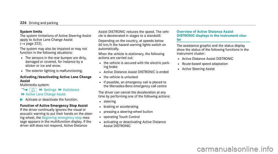
Assi stDISTRONIC Overvi
ewofActive Di stance Assist
DISTRO NIC displa ysinthe instrument clus‐
ter The assis
tance graphic and thest atus display
show thest atus of thefo llowing functions in the
instrument clus ter:
R Active Dis tance Assi stDISTRONIC
R Route-based speed adap tation
R Active Steering Assist 226
Driving and parking
Page 231 of 657
tions
tothe speed due tomanual or auto matic
adoption of the speed limit, are displa yed in the
control feedback of the multifunction display on
a single line.
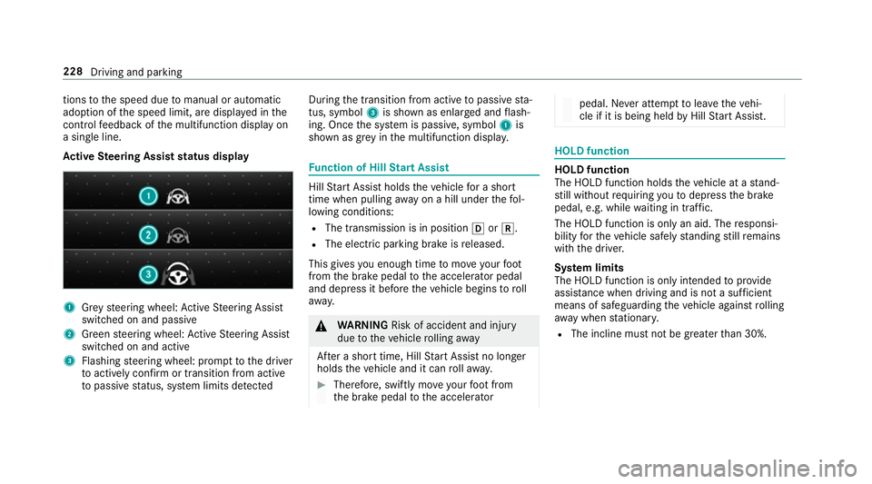
Ac tive Steering Assist status display 1
Grey steering wheel: Active Steering Assist
switched on and passive
2 Green steering wheel: Active Steering Assist
switched on and active
3 Flashing steering wheel: prom pttothe driver
to actively con firm or transition from active
to passive status, sy stem limits de tected During
the transition from active topassive sta‐
tus, symbol 3is shown as enlar ged and flash‐
ing. Once the sy stem is passive, symbol 1is
shown as gr eyinthe multifunction displa y. Fu
nction of Hill Start Assist Hill
Start Assist holds theve hicle for a short
time when pulling away on a hill under thefo l‐
lowing conditions:
R The transmission is in position hork.
R The elect ric pa rking brake is released.
This gives you enough time tomo veyour foot
from the brake pedal tothe accelera tor pedal
and depress it before theve hicle begins toroll
aw ay. &
WARNING Risk of accident and inju ry
due totheve hicle rolling away
Af ter a short time, Hill Start Assist no lon ger
holds theve hicle and it can rollaw ay. #
Therefore, swiftly mo veyour foot from
th e brake pedal tothe accelerator pedal. Ne
ver attem pttolea vetheve hi‐
cle if it is being held byHill Start Assist. HOLD function
HOLD function
The HOLD function holds
theve hicle at a stand‐
st ill without requ iring youto depress the brake
pedal, e.g. while waiting in traf fic.
The HOLD function is only an aid. The responsi‐
bility forth eve hicle safely standing still remains
with the driver.
Sy stem limits
The HOLD function is only intended toprov ide
assis tance when driving and is not a su fficient
means of safeguarding theve hicle against rolling
aw ay when stationar y.
R The incline must not be greater than 30%. 228
Driving and parking
Page 233 of 657
R
The vehicle is secured with the electric park‐
ing brake.
In thefo llowing situations, theve hicle is held by
th e transmission position jorby the electric
parking brake:
R The seat belt is unfas tened and the driver's
door is opened.
R The vehicle is switched off.
R There is a malfunction in the sy stem or the
po we r supp lyis insuf ficient. DY
NA MIC BODY CONT ROL function DY
NA MIC BODY CONTROL continuously adjusts
th ech aracteristics of the suspension dampers to
th e cur rent operating and driving conditions.
The da mping is tuned individually for each wheel
and is af fected bythefo llowing factors:
R The road sur face conditions R
Vehicle load
R The drive program selected
R The driving style
The drive program can be adjus ted using the
DY NA MIC SELECT switch. AIR
BODY CONT ROL AIR
BODY CONT ROL function
AIR BODY CONTROL is an air suspension sy stem
with variable damping for impr oved driving com‐
fo rt. The all-round le vel control sy stem ensures
th e best possible suspension and const ant
ground clearance, even with a laden vehicle.
When driving at speed, theve hicle is lo wered
automatically toimpr ovedriving saf ety and to
re duce fuel consum ption. You also ha vethe
option of manually adjusting theve hicle le vel. AIR
BODY CONTROL includes thefo llowing com‐
ponents and functions:
R air suspension with variable spring rate
R automatic le vel control sy stem
R speed-dependent lo wering toreduce fuel
consum ption
R manually selec table high le vel setting for
grea ter ground clea rance
R ADS PLUS (Ada ptive Damping Sy stem with
const ant damping forc e adjustment)
R DYNA MIC SELECT switch and le vel button 230
Driving and parking
Page 235 of 657
Dif
fere nces between di fferent vehicle le vels
compared tothe normal le vel (0):
R High le vel +1: approx. +15 mm (Brazil:
appr ox. +30 mm)
R Low le vel -1: approx. -15 mm
Sets the vehicle le vel &
WARNING Risk of accident because
ve hicle le vel is too high
If yo u drive at a higher vehicle le vel,th e driv‐
ing characteristics may be impaired due to
th e higher vehicle centre of gravity.
The vehicle can drift outwards, forex ample,
when steering or cornering. #
Alw aysch oose a vehicle le vel which is
suited tothe driving style and thero ad
sur face conditions. &
WARNING Risk of entrapment from vehi‐
cle lo wering
When lo wering theve hicle, other people
could become trapped if their limbs are between
theve hicle body and the tyres or
underneath theve hicle. #
Make sure no one is underneath the
ve hicle or in the immediate vicinity of
th e wheel ar ches when theve hicle is
being lo wered. &
WARNING Risk of becoming trapped
due totheve hicle lo wering
Ve hicles with AIR BODY CONT ROL or
le ve l control sy stem: when you unload lug‐
ga ge or lea vetheve hicle, theve hicle first
ri ses slightly and then returns tothe set le vel
shortly af terw ards.
Yo u or an yone else in the vicinity of the
wheel ar ches or the underbody could thus
become trapped.
The vehicle can also be lo wered af ter being
loc ked. #
When leaving theve hicle, make sure
th at nobody is in the vicinity of the
wheel ar ches or the underbody. *
NO
TEDama gedue tovehicle lo wering Pa
rts of the body could be damaged when
th eve hicle is lo wered. #
Make sure that there are no obs tacles
su ch askerbs underneath or in the
immediate vicinity of the body when the
ve hicle is being lo wered. Re
quirements:
R The vehicle has been star ted.
R The vehicle must not be moving fasterthan
60 km/h. 232
Driving and parking
Page 243 of 657

The articulation angle can be
changed on the
media display or on theto uchpad. #
Swipe left or right tochange the articulation
angle.
% The maximum articulation angle depends on
th e length of the trailer. This is calculated by
th e sy stem bydriving theve hicle forw ards,
including cornering. Before the length of the
trailer has been calculated, the maximum
articulation angle is appr oximately 23°. The
longer the trailer is, the higher the maximum
articulation angle (max. appr oximately 60°). #
Set the desired articulation angle.
When the articulation angle entered has been
re ached, the dr awbar is loc kedby the sy stem so
th at the angle is maintained.
Ac tivating the stra ightening manoeuvre #
Select .
The sy stem calculates the articulation angle
in such a wayth at the direction of the trailer
at the time of activation is maintained. There is a short counter
steering mo vement of the
trailer while theve hicle is reve rsed, which
th en guides it back tothe desired line. In this
wa y,theve hicle is aligned stra ight with the
trailer and, at the same time, the direction of
th e trailer is maintained. Re
versing camera Fu
nction of there ve rsing camera If
yo u ha veactivated the function in the multime‐
dia sy stem (/ page247), the image from
re ve rsing camera 1is shown in the media dis‐
play when there ve rsege ar is engaged. Dynamic
guide lines show the path theve hicle will take
with thesteering wheel in its cur rent position. 240
Driving and pa rking
Page 244 of 657

This helps
youto orient yourself and to avoid
obs tacles when reve rsing.
The reve rsing camera is only an aid. It is not a
substitute foryo ur attention tothe sur roundings.
The responsibility for safe manoeuvring and
parking remains with you. Make sure that there
are no persons, animals or objects etc., in the
manoeuvring area while manoeuvring and park‐
ing.
The guide lines in the media display show the
dis tances to yourvehicle. The dis tances dis‐
pl ay ed only apply toroad le vel.
Depending on theve hicle equipment, you can
select from thefo llowing vie ws:
R Normal view
R Wide-angle view
R Trailer view
The area behind theve hicle is displa yed as a
mir ror image, as in the inside rearview mir ror.
Ve hicles without Active Parking Assist
The following camera vie wsare available in the
multimedia sy stem: Normal view
1 Yellow guide line, vehicle width (driven sur‐
fa ce) depending on the cur rent steering
wheel angle (dynamic)
2 Yellow guide line at a dis tance of appr ox‐
imately 1.0 m from there ar area
3 Yellow lane marking the course the tyres will
ta ke atthe cur rent steering wheel angle
(dynamic)
4 Bumper
5 Red guide line at a dis tance of appr oximately
0.3 m from there ar area Wi
de-angle view Tr
ailer view (vehicles with a trailer hit ch)
1 Yellow guide line, locating aid Driving and parking
241
Page 245 of 657
2
Red guide line at a dis tance of appr oximately
0.3 m from the ball head of the trailer hitch
3 Ball head of the trailer hitch
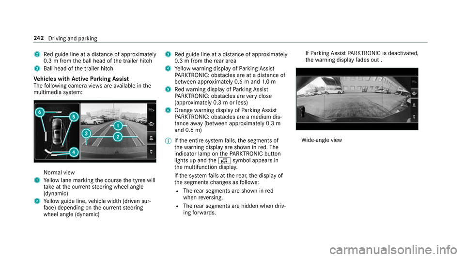
Ve hicles with Active Parking Assist
The following camera vie wsare available in the
multimedia sy stem: Normal view
1 Yellow lane marking the course the tyres will
ta ke atthe cur rent steering wheel angle
(dynamic)
2 Yellow guide line, vehicle width (driven sur‐
fa ce) depending on the cur rent steering
wheel angle (dynamic) 3
Red guide line at a dis tance of appr oximately
0.3 m from there ar area
4 Yellow warning display of Parking Assist
PA RKTRONIC: obstacles are at a dis tance of
between appr oximately 0.6 m and 1.0 m
5 Redwa rning display of Parking Assist
PA RKTRONIC: obstacles are very close
(appr oximately 0.3 m or less)
6 Orange warning display of Parking Assist
PA RKTRONIC: obstacles are a medium dis‐
ta nce away (between appr oximately 0.3 m
and 0.6 m)
% Ifth e entire sy stem fails, the segments of
th ewa rning display are shown in red. The
indicator lamp on thePA RKTRONIC but ton
lights up and theé symbol appears in
th e multifunction displa y.
If th e sy stem fails at there ar, the display of
th e segments changes as follo ws:
R The rear segments are shown in red
when reve rsing.
R The rear segments are hidden when driv‐
ing forw ards. If
Pa rking Assist PARKTRONIC is deacti vated,
th ewa rning display fades out . Wi
de-angle view 242
Driving and pa rking