2019 MERCEDES-BENZ GLB SUV clock
[x] Cancel search: clockPage 492 of 689
To
pping up engine oil &
WARNING Risk of bu rns from hot com‐
ponent parts in the engine compartment
Cer tain components in the engine compart‐
ment can be very hot, e.g. the engine, the
ra diator and parts of theex haust sy stem. #
Allow the engine tocool down and only
to uch co mponent parts described in
th efo llowing. &
WARNING Risk offire and injury from
engine oil
If engine oil comes into con tact wi thhot
component parts in the engine compart‐
ment, it may ignite. #
Make sure that no engine oil is spilled
next tothefiller opening. #
Allow the engine tocool off and thor‐
oughly clean the engine oil from compo‐
nent parts before starting theve hicle. *
NO
TEEngine dama gecaused byan
incor rect oil filter, incor rect oil or addi‐
tives #
Do not use engine oils or oil filters
which do not cor respond tothe specifi‐
cations explicitly prescribed forthe
service inter vals. #
Do not alter the engine oil or oil filter in
order toachie velonger change inter vals
th an presc ribed. #
Do not use additives. #
Follow the instructions in the service
inter val display rega rding the oil
ch ange. *
NO
TEDama gecaused bytopping up too
much engine oil To
o much engine oil can damage the engine
or the catalytic con verter. #
Have excess engine oil remo ved at a
qu alified specialist workshop. #
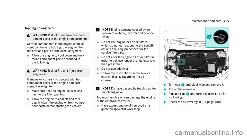
Turn cap 1anti-clockwise and remo veit. #
Top up the engine oil. #
Replace cap 1and turn it clockwise as far
as it will go. #
Check the oil le vel again (/ page 488). Maintenance and care
489
Page 493 of 689
Checking
the coolant le vel &
WARNING Risk of bu rns from hot com‐
ponent parts in the engine compartment
Cer tain components in the engine compart‐
ment can be very hot, e.g. the engine, the
ra diator and parts of theex haust sy stem. #
Allow the engine tocool down and only
to uch co mponent parts described in
th efo llowing. &
WARNING Risk of scalding from hot
coolant
The engine cooling sy stem is pressurised,
particularly when the engine is warm. If you
open the cap, you could be scalded byhot
coolant spr aying out. #
Let the engine cool down before open‐
ing the cap. #
When opening the cap, wear pr otective
gl ove s and saf etygl asses. #
Open the cap slowly torelease pres‐
sure. #
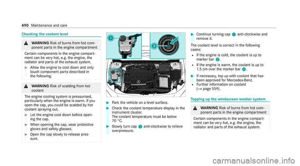
Park theve hicle on a le vel sur face. #
Check the coolant temp erature display in the
instrument clus ter.
The coolant temp erature must be below
70 °C. #
Slowly turn cap 1anti-clockwise torelie ve
ov erpressure. #
Continue turning cap 1anti-clockwise and
re mo veit.
The coolant le vel is cor rect in thefo llowing
cases:
R ifth e engine is cold, the coolant is up to
mar ker bar 2.
R ifth e engine is warm,th e coolant is up to
1. 5 cm overth e mar ker bar 2. #
If necessar y,top up with coolant that has
been appr ovedfo r Mercedes-Benz.
R Further information on coolant
(/ page 559). To
pping up the windsc reen washer sy stem &
WARNING Risk of bu rns from hot com‐
ponent parts in the engine compartment
Cer tain components in the engine compart‐
ment can be very hot, e.g. the engine, the
ra diator and parts of theex haust sy stem. 490
Maintenance and care
Page 510 of 689
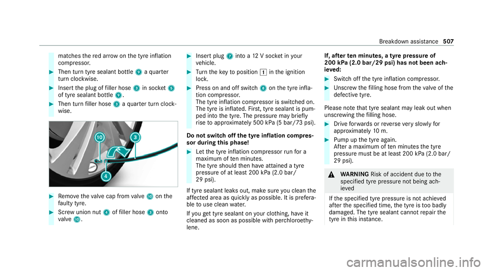
matches
there d ar row on the tyre inflation
compressor. #
Then turn tyre sealant bottle 9aqu arter
turn clo ckwise. #
Insert the plug of filler hose 3in soc ket5
of tyre sealant bottle 9.#
Then turn filler hose 3aqu arter turn clock‐
wise. #
Remo vetheva lve cap from valve A onthe
fa ulty tyre. #
Screw union nut 4offiller hose 3onto
va lve A. #
Insert plug 7into a 12V soc ket in your
ve hicle. #
Turn theke yto position 1inthe ignition
loc k. #
Press on and off switch 8onthe tyre infla‐
tion compressor.
The tyre inflation compressor is switched on.
The tyre is inflated. Fir st, tyre sealant is pum‐
ped into the tyre. The pressure may brief ly
ri se toappr oximately 500 kPa (5 bar/73 psi).
Do not switch off the ty reinflation compres‐
sor during this phase! #
Let the tyre inflation compressor runfo r a
maximum of ten minu tes.
The tyre should then ha veattained a tyre
pressure of at least 200 kPa (2.0 bar/
29 psi).
If tyre sealant leaks out, make sure you clean the
af fected area as quickly as possible. It is prefera‐
ble touse clean water.
If yo uge t tyre sealant on your clo thing, ha veit
cleaned as soon as possible with per chloroe thy‐
lene. If, af
terte n minutes, a tyre pressure of
200 kPa (2.0 bar/29 psi) has not been ach‐
ie ve d: #
Switch off the tyre inflation compressor. #
Unscr ew thefilling hose from theva lve of the
defective tyre.
Please no tethat tyre sealant may leak out when
unscr ewing thefilling hose. #
Drive forw ards or reve rseve ry slowly for
appr oximately 10m. #
Pump up the tyre again.
Af ter a maximum of ten minu testh e tyre
pressure must be at least 200 kPa (2.0 bar/
29 psi). &
WARNING Risk of accident due tothe
specified tyre pressure not being ach‐
ie ved
If th e specified tyre pressure is not achie ved
af te rth e specified time, the tyre is too badly
damaged. The tyre sealant cannot repair the
tyre in this ins tance. Breakdown assi
stance 507
Page 522 of 689
To
wing eyesto rage location To
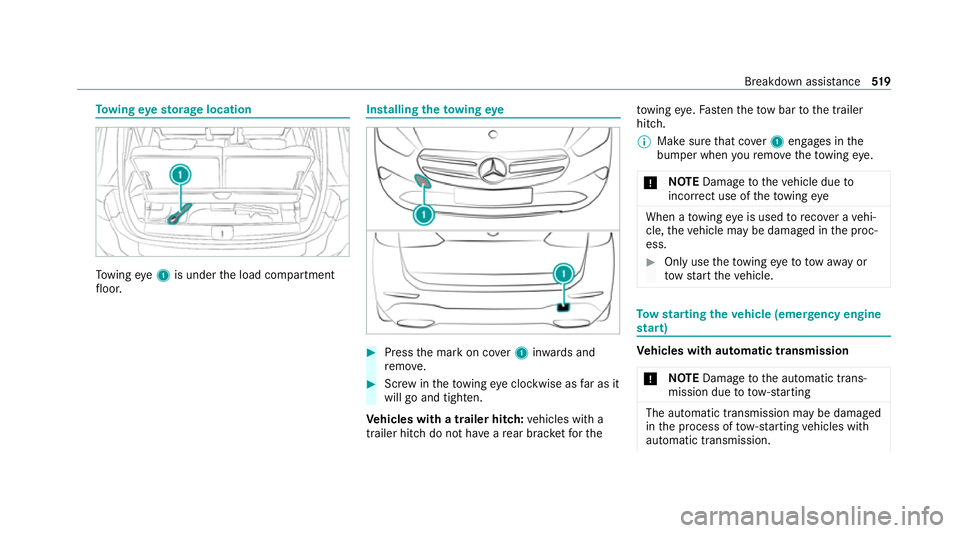
wing eye1 is under the load compartment
fl oor. Installing
theto wing eye #
Press the mark on co ver1 inwa rds and
re mo ve. #
Screw intheto wing eyeclockwise as far as it
will go and tighten.
Ve hicles with a trailer hitch: vehicles with a
trailer hitch do not ha veare ar brac ketfo rthe to
wing eye. Fasten theto w bar tothe trailer
hitch.
% Make sure that co ver1 engages in the
bumper when youre mo vetheto wing eye.
* NO
TEDama getotheve hicle due to
incor rect use of theto wing eye When a
towing eye is used toreco ver a vehi‐
cle, theve hicle may be damaged in the proc‐
ess. #
Only use theto wing eyeto to waw ay or
to w start theve hicle. To
w starting theve hicle (eme rgency engine
st art) Ve
hicles with automatic transmission
* NO
TEDama getothe automatic trans‐
mission due to tow-starting The automatic transmission may be damaged
in the process of tow- starting vehicles with
automatic transmission. Breakdown assis
tance 519
Page 542 of 689
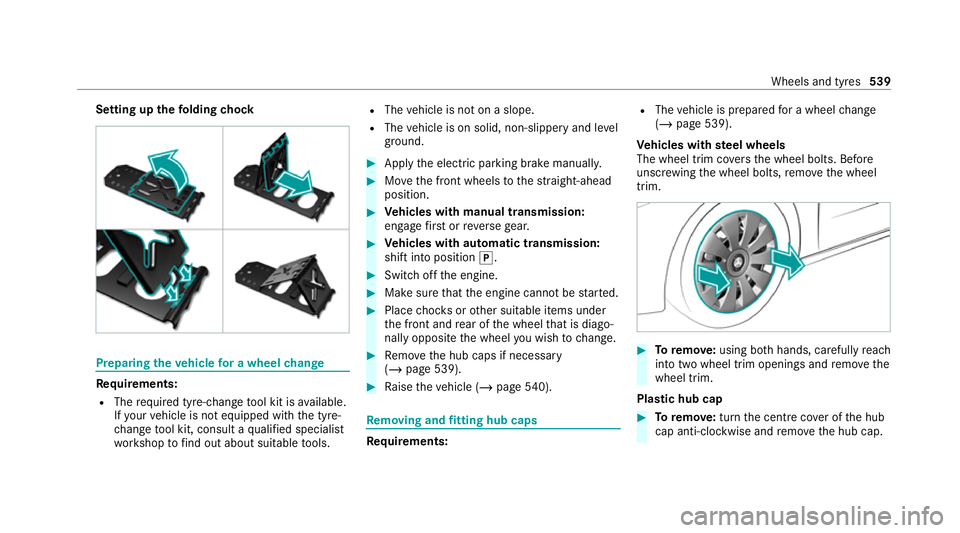
Setting up
thefo lding chock Prepa
ring theve hicle for a wheel change Re
quirements:
R The requ ired tyre-change tool kit is available.
If yo ur vehicle is not equipped with the tyre-
ch ange tool kit, consult a qualified specialist
wo rkshop tofind out about suitable tools. R
The vehicle is not on a slope.
R The vehicle is on solid, non-slippery and le vel
ground. #
Apply the electric parking brake manually. #
Movethe front wheels tothest ra ight-ahead
position. #
Vehicles with manual transmission:
engage firs t or reve rsege ar. #
Vehicles with automatic transmission:
shift into position j. #
Switch off the engine. #
Make sure that the engine cann otbe star ted. #
Place choc ks orother suitable items under
th e front and rear of the wheel that is diago‐
nally opposite the wheel you wish tochange. #
Remo vethe hub caps if necessary
(/ page 539). #
Raise theve hicle (/ page540). Re
moving and fitting hub caps Re
quirements: R
The vehicle is prepared for a wheel change
(/ page 539).
Ve hicles with steel wheels
The wheel trim co vers the wheel bolts. Before
unscr ewing the wheel bolts, remo vethe wheel
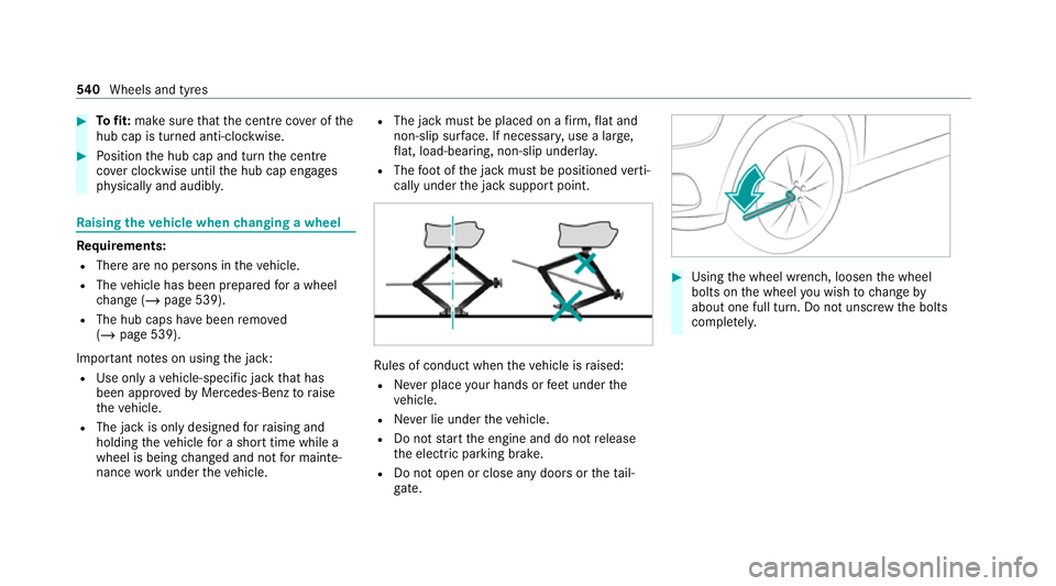
trim. #
Toremo ve:using bo thhands, carefully reach
into two wheel trim openings and remo vethe
wheel trim.
Plastic hub cap #
Toremo ve:turn the cent recover of the hub
cap anti-clockwise and remo vethe hub cap. Wheels and tyres
539
Page 543 of 689
#
Tofit: make sure that the cent recover of the
hub cap is turned anti-clockwise. #
Position the hub cap and turn the cent re
co ver clockwise until the hub cap engages
ph ysically and audibly. Ra
ising theve hicle when changing a wheel Re
quirements:
R There are no persons in theve hicle.
R The vehicle has been prepared for a wheel
ch ange (/ page 539).
R The hub caps ha vebeen remo ved
( / page 539).
Impor tant no tes on using the jack:
R Use only a vehicle-specific jack that has
been appr oved byMercedes-Benz toraise
th eve hicle.
R The jack is only designed forra ising and
holding theve hicle for a short time while a
wheel is being changed and not for mainte‐
nance workunder theve hicle. R
The jack must be placed on a firm ,fl at and
non-slip sur face. If necessar y,use a lar ge,
fl at, load-bearing, non-slip unde rlay.
R The foot ofthe jack must be positioned verti‐
cally under the jack support point. Ru
les of conduct when theve hicle is raised:
R Never place your hands or feet under the
ve hicle.
R Never lie under theve hicle.
R Do not start the engine and do not release
th e electric parking brake.
R Do not open or close any doors or theta il‐
gate. #
Using the wheel wrench, loosen the wheel
bolts on the wheel you wish tochange by
about one full turn. Do not unscr ewthe bolts
comple tely. 540
Wheels and tyres
Page 544 of 689
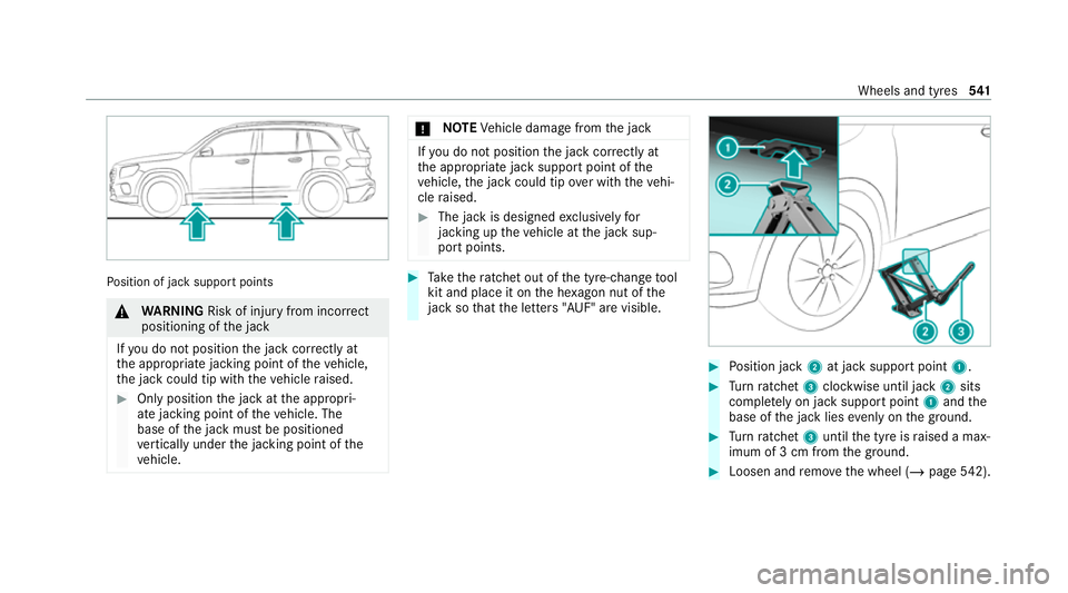
Po
sition of jack support points &
WARNING Risk of inju ryfrom incor rect
positioning of the jack
If yo u do not position the jack cor rectly at
th e appropriate jacking point of theve hicle,
th e jack could tip with theve hicle raised. #
Only position the jack at the appropri‐
ate jacking point of theve hicle. The
base of the jack must be positioned
ve rtically under the jacking point of the
ve hicle. *
NO
TEVehicle damage from the jack If
yo u do not position the jack cor rectly at
th e appropriate jack support point of the
ve hicle, the jack could tip over with theve hi‐
cle raised. #
The jack is designed exclusively for
jacking up theve hicle at the jack sup‐
port points. #
Take thera tchet out of the tyre-change tool
kit and place it on the he xagon nut of the
jack so that the letters "AUF" are visible. #
Position jack 2at jack support point 1. #
Turn ratchet 3clockwise until jack 2sits
comple tely on jack support point 1and the
base of the jack lies evenly on the ground. #
Turn ratchet 3until the tyre is raised a max‐
imum of 3 cm from the ground. #
Loosen and remo vethe wheel (/ page542). Wheels and tyres
541