2019 MERCEDES-BENZ EQC SUV brake light
[x] Cancel search: brake lightPage 10 of 629
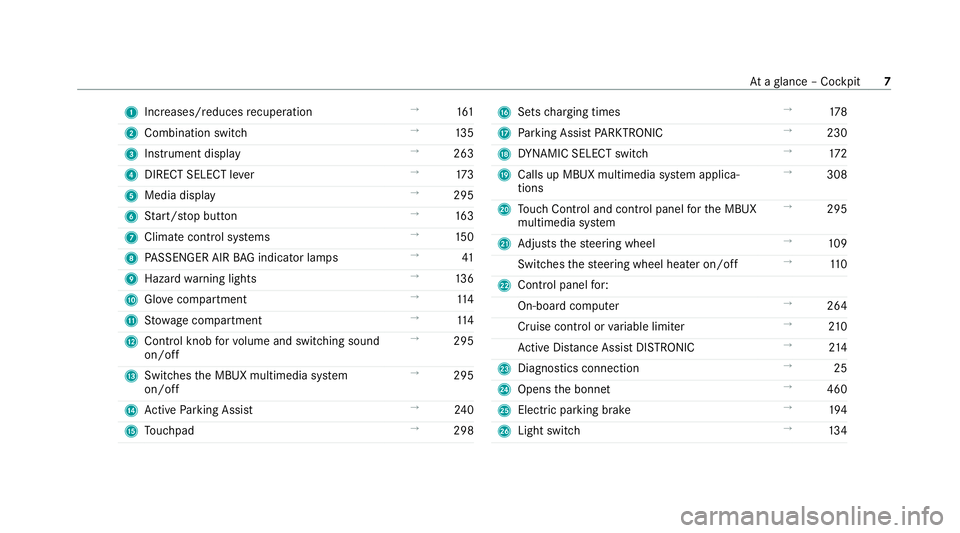
1
Increases/reduces recuperation →
161
2 Combination swit ch →
13 5
3 Instrument display →
263
4 DIRECT SELECT le ver →
173
5 Media display →
295
6 Start/ stop button →
16 3
7 Climate cont rol sy stems →
15 0
8 PASSENGER AIR BAG indicator lamps →
41
9 Haza rdwa rning lights →
13 6
A Glovecompa rtment →
11 4
B Stow age compartment →
11 4
C Control knob forvo lume and switching sound
on/off →
295
D Swit ches the MBUX multimedia sy stem
on/off →
295
E Active Parking Assist →
24 0
F Touchpad →
298 G
Sets charging times →
178
H Parking Assist PARKTRONIC →
230
I DYNA MIC SELECT switch →
172
J Calls up MBUX multimedia sy stem applica‐
tions →
308
K Touch Control and cont rol panel forth e MBUX
multimedia sy stem →
295
L Adjusts thesteering wheel →
109
Switches thesteering wheel heater on/off →
11 0
M Control panel for:
On-board computer →
264
Cruise contro l orvariable limiter →
210
Ac tive Dis tance Assi stDISTRONIC →
214
N Diagno stics connection →
25
O Opens the bonn et →
460
P Electric parking brake →
194
Q Light switch →
13 4 At
aglance – Cockpit 7
Page 12 of 629
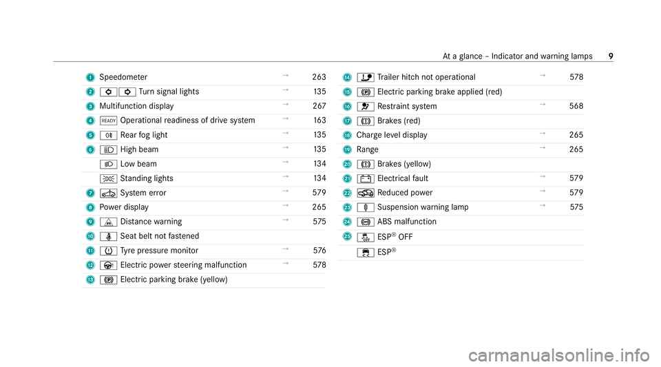
1
Speedom eter →
263
2 #! Turn signal lights →
13 5
3 Multifunction display →
267
4 õ Operational readiness of drive sy stem →
16 3
5 R Rear fog light →
13 5
6 K High beam →
13 5
L Low beam →
13 4
T Standing lights →
13 4
7 Ú System er ror →
579
8 Powe r display →
265
9 L Distance warning →
575
A ü Seat belt not fastened
B h Tyre pressure monitor →
576
C Ù Electric po werst eering malfunction →
578
D ! Electric pa rking brake (yellow) E
ï Trailer hit chnot operational →
578
F ! Electric pa rking brake applied (red)
G 6 Restra int sy stem →
568
H J Brakes (red)
I Charge le vel display →
265
J Range →
265
K J Brakes (yellow)
L # Electrical fault →
579
M O Reduced po wer →
579
N ä Suspension warning lamp →
575
O ! ABS malfunction
P å ESP®
OFF
÷ ESP® At
aglance – Indicator and warning lamps 9
Page 30 of 629

QR code
forre scue card
The QR code is secured in the fuel filler flap and
on the opposite side on the B-pillar. In theeve nt
of an accident, rescue services can use the QR
code toquickly find the appropriate rescue card
fo ryo ur vehicle. The cur rent rescue card con‐
ta ins the most impor tant information about your
ve hicle in a compact form , e.g. thero uting of the
electric lines.
Fu rther information can be obtained at http://
www.mercedes-benz.de/qr-code. Data
storage Electronic control units
Elect
ronic control units are fitted in your vehicle.
Some of these are necessary forth e safe opera‐
tion of your vehicle, while some assist you when
driving (driver assis tance sy stems). In addition,
yo ur vehicle pr ovides com fort and enter tainment
functions, which are also made possible byelec‐
tronic control units.
Elect ronic control units contain da tamemories
which can temp orarily or permanently store te
ch nical information about theve hicle's operat‐
ing state, component loads, main tenance
re qu irements and tech nical events or faults.
In general, this information documents thest ate
of a component part, a module, a sy stem or the
sur roundings such as:
R operating status of sy stem components (e.g.
fi ll le vels, battery status, tyre pressure)
R status messages concerning theve hicle or
its individual components (e.g. number of
wheel revo lutions/speed, longitudinal accel‐
eration, lateral acceleration, display of fas‐
te ned seat belts)
R malfunctions or faults in impor tant sy stem
components (e.g. lights, brakes)
R information on events leading tovehicle
damage
R system reactions in special driving situations
(e.g. airbag deployment, inter vention of sta‐
bility control sy stems)
R ambient conditions (e.g. temp erature, rain
sensor) In addition
toprov iding the actual control unit
function, this data assists the manufacturer in
de tecting and rectifying faults and optimising
ve hicle functions. The majority of this data is
te mp orary and is only processed in theve hicle
itself. Only a small portion of the data is stored
in theeve nt or fault memor y.
When your vehicle is serviced, tech nical da ta
from theve hicle can be read out byservice net‐
wo rkemplo yees (e.g. workshops, manufactur‐
ers) or third parties (e.g. breakdown services).
Services include repair services, maintenance
processes, warranty claims and quality assur‐
ance measures, forex ample. The read out is per‐
fo rm ed via the legally prescribed port forthe
diagnostics connection in theve hicle. The
re spective service network locations or third
parties collect, process and use the data. They
document tech nical statuses of theve hicle,
assist in finding faults and impr oving quality and
are transmitted tothe manufacturer, if neces‐
sar y.Fu rthermore, the manufacturer is subject
to product liability. Forth is, the manufacturer
requ irestech nical da tafrom vehicles. General no
tes27
Page 48 of 629
Re
versing the PRE- SAFE®
sy stem measures If an accident did not occur,
the pre-em ptive
measures that we retak en are reve rsed.
Yo u will need toper form certain settings your‐
self. #
Ifth e seat belt pre-tensioning is not reduced,
mo vethe seat backrest back slightl y.
The locking mechanism releases. Fu
nction of PRE-SAFE ®
PLUS (anticipatory
occupant pr otection plus) PRE-
SAFE®
PLUS can de tect cer tain impacts,
particular lyan imminent rear impact, and take
pre-em ptive measures toprotect theve hicle
occupants. These measures cannot necessarily
pr eve nt an imminent impact.
PRE-SAFE ®
PLUS can implement thefo llowing
measures independently of each other:
R Tightening the seat belts on the driver's seat
and front passenger seat.
R Activating there ar hazard warning lights at a
higher flashing frequenc y. R
Increasing brake pressure when theve hicle
is stationar y.This brake application is cancel‐
led automatically when theve hicle pulls
aw ay.
If an accident did not occur, the pre-em ptive
measures that we retake n are reve rsed.
Sy stem limits
The sy stem will not initiate any action in thefo l‐
lowing situations:
R when reve rsing
or
R when theve hicle is towing a trailer and there
is a risk of a rear impact
The sy stem will not initiate any braking applica‐
tion in thefo llowing situations:
R whilst driving
or
R when entering or exiting a parking space
while using Active Parking Assist Safely transporting
children in theve hicle Alw
ays obser vewhen children are tr avelling
in theve hicle %
Also strictly obser vethe saf ety no tesfo rthe
specific situation. In this wa yyo u can recog‐
nise po tential risks and avoid dangers if chil‐
dren are tr avelling in theve hicle
(/ page 46).
Be diligent
Bear in mind that neglecting tosecure a child in
th ech ild restra int sy stem may ha veserious con‐
sequences. Alw ays be diligent in securing a child
carefully before everyjou rney.
To impr oveprotection forch ildren younger than
12 years old or under 1.50 m in height,
Mercedes-Benz recommends you obse rvethe
fo llowing information:
R Alw ays secure thech ild in a child restra int
sy stem suitable forth is Mercedes-Benz vehi‐
cle.
R The child restra int sy stem must be appropri‐
ate tothe age, weight and size of thech ild. Occupant saf
ety45
Page 75 of 629
Key
Overview of
key functions &
WARNING Risk of accident and inju ry
due tochildren left unat tended in the
ve hicle
If ch ildren are left unat tended in theve hicle,
th ey could:
R Open doo rs,th ereby endangering other
persons or road users.
R Get out and be stru ck byoncoming traf‐
fi c.
R Ope rate ve hicle equipment and become
trapped, forex ample.
In addition, thech ildren could also set the
ve hicle in motion, forex ample by:
R Releasing the parking brake.
R Changing the transmission position.
R Starting theve hicle. #
Never lea vechildren unat tended in the
ve hicle. #
When leaving theve hicle, alw aysta ke
th eke y with you and lock theve hicle. #
Keep theve hicle key out of reach of
ch ildren. This also applies
tothe Digital Vehicle Key if the
"Digital Vehicle Key" function is activated via
Mercedes me connect.
* NO
TEDama getotheke y caused by
magnetic fields #
Keep theke yaw ay from strong mag‐
netic fields. %
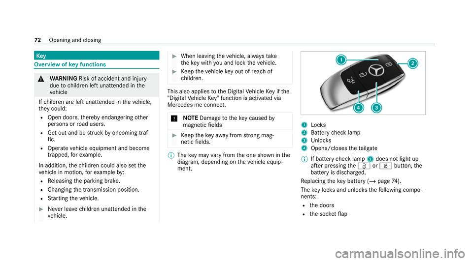
The key may vary from the one shown in the
diagram, depending on theve hicle equip‐
ment. 1
Locks
2 Battery check lamp
3 Unloc ks
4 Opens/closes theta ilgate
% If battery check lamp 2does not light up
af te r pressing theÜ orß button, the
battery is dischar ged.
Re placing theke y bat tery ( / page 74).
The key loc ksand unlo cksth efo llowing compo‐
nents:
R the doors
R the soc ketflap 72
Opening and closing
Page 139 of 629
High beam
#
Toswitch on: turnthe light switch tothe
L orà position. #
Press the combination switch be yond the
point of resis tance in the direction of ar row
1 .
When the main beam is activated, the indica‐
to r lamp for dipped beam Lis deactiva‐
te d and replaced bythe indicator lamp for
th e main beam K.#
Toswitch off: movethe combination switch
back toits starting position.
Headla mpflasher #
Pull the combination switch in the direction
of ar row3.
Tu rn signal indicators #
Toindicate briefl y:press the combination
switch briefly tothe point of resis tance in the
direction of ar row2or4.
The cor responding turn signal indicator will
fl ash thre e times. #
Toindicate permanentl y:press the combi‐
nation switch be yond the point of resis tance
in the direction of ar row2or4.
Ve hicles with Active Lane Change Assi st:
R Indicator operation activated bythe driver
can extend forth e duration of the lane
ch ange.
R Ifth e driver indicated directly beforehand
but a lane change was not immediately
possible, the turn signal indicator may
activate automaticall y. Ac
tivating/deactivating the hazard warning
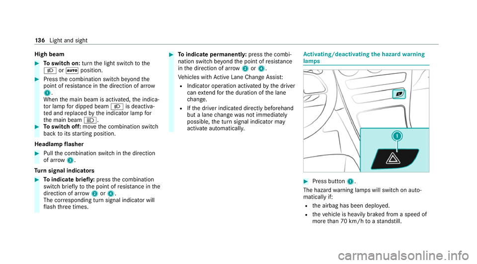
lamps #
Press button 1.
The hazard warning lamps will switch on auto‐
matically if:
R the airbag has been deplo yed.
R theve hicle is heavily braked from a speed of
more than 70 km/h toast andstill. 13 6
Light and sight
Page 162 of 629

The component parts in
theve hicle's high-
vo ltage on-board elect rical sy stem may be
damaged in an accident, although the dam‐
age is not visible. #
Never car ryout changes on the high-
vo ltage on-board elect rical sy stem. #
Neverto uch co mponent parts in the
high-voltage on-board electrical sy stem. #
After an accident, do not touch any
high-voltage co mponents. #
After an accident, ha vetheve hicle
transpor tedaw ay. #
Have the high-voltage on-board electri‐
cal sy stem checked at a qualified spe‐
cialist workshop. Re
quirements:
R The 6 restra int sy stem warning lamp
lights up in the instrument clus ter,e.g. af ter
an accident.
R The vehicle is badly damaged, e.g. af ter an
accident, and there stra int sy stem compo‐
nents ha venot been trig gered. Operating
the high-voltage disconnect
device
On lydisconnect the drive sy stem manually in
th e abo ve-mentioned situations. #
Switch off the ignition. #
Shift the transmission toposition j. #
Apply the electric parking brake. #
Secure theve hicle against rolling away. #
Open the bonn et. 1
High-voltage disconnect device label on the
engine compartment co ver #
Using bo thhands, reach into there cesses of
th e engine compartment co ver. #
Lift the engine compartment co ver and pull it
out of the engine compartment in the direc‐
tion of the ar row. #
Place the engine compartment co verto one
side. Driving and parking
15 9
Page 166 of 629
#
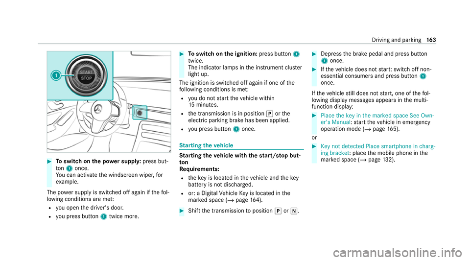
Toswitch on the po wer supp ly:press but‐
to n1 once.
Yo u can activate the windscreen wiper, for
ex ample.
The po wer supp lyis switched off again if thefo l‐
lowing conditions are me t:
R you open the driver's door.
R you press but ton1 twice more. #
Toswitch on the ignition: press button 1
twice.
The indicator lamps in the instrument clus ter
light up.
The ignition is switched off again if one of the
fo llowing conditions is me t:
R you do not start theve hicle within
15 minutes.
R the transmission is in position jorthe
electric parking brake has been applied.
R you press but ton1 once. St
arting theve hicle St
arting theve hicle with thest art/s top but‐
ton
Requ irements:
R theke y is located in theve hicle and thekey
battery is not dischar ged.
R or: a Digital Vehicle Key is located in the
mar ked space (/ page164). #
Shift the transmission toposition jori. #
Depress the brake pedal and press button
1 once. #
Ifth eve hicle does not star t:switch off non-
essential consumers and press button 1
once.
If th eve hicle still does not start, one of thefo l‐
lowing display messages appears in the multi‐
function display: #
Place the key in the marked space See Own-
er's Manual :st art theve hicle in emer gency
operation mode (/ page 165).
or #
Key not detected Place smartphone in charg-
ing bracket: place the mobile phone in the
mar ked space (/ page132). Driving and pa
rking 16 3