2019 MERCEDES-BENZ AMG GT ROADSTER wheel bolt torque
[x] Cancel search: wheel bolt torquePage 23 of 298
Two-way radio
Frequencies ................................... 287
Installation ..................................... 287
Transmission output (maximum) .... 287
Type identification plate
see Vehicle identification plate U
Unlocking Emergency unlocking ....................... 73
From inside the vehicle (central
unlocking button) ............................. 72
USB devices
Connecting to the Media Inter-
face .............................................. .217 V
Vanity mirror (in the sun visor) ........221
Vehicle
Correct use ...................................... 28
Data acquisition ............................... 29
Display message ............................ 194
Electronics ..................................... 287
Equipment ....................................... 25
Individual settings .......................... 168
Limited Warranty ............................ .29
Loading .......................................... 271
Locking (in an emergency) ............... 73
Locking (SmartKey) .......................... 66
Lowering ........................................ 285
Maintenance .................................... 26
Operating safety .............................. 26
Parking .......................................... 127
Parking for a long period ................ 130
Pulling away ................................... 112
Raising ........................................... 282
Reporting problems ......................... 28
Securing from rolling away ............ 282
Towing away .................................. 258
Transporting .................................. 260
Unlocking (in an emergency) ........... 73
Unlocking (SmartKey )...................... 66
Vehicle data ................................... 293
Vehicle battery
see Battery (vehicle)
Vehicle data
Trunk load (maximum) ................... 293 Vehicle dimensions
........................... 293
Vehicle emergency locking ................ 73
Vehicle identification number
see VIN
Vehicle identification plate .............. 287
Vehicle maintenance
see ASSYST PLUS
Vehicle tool kit .................................. 249
Ventilation
see Climate control
Video
Operating the DVD ......................... 166
see also Digital Operator's Man-
ual .................................................. 209
VIN
Seat ............................................... 288
Type plate ...................................... 287 W
Warning and indicator lamps ABS ................................................ 201
Active Brake Assist ........................ 206
Brakes ........................................... 200
Check Engine ................................. 204
Coolant .......................................... 204
Distance warning ........................... 206
ESP ®
.............................................. 201
ESP ®
OFF ....................................... 202
Fuel tank ........................................ 204
Overview .......................................... 34
Parking brake ................................ 203
PASSENGER AIR BAG ...................... 41
Reserve fue l................................... 204
Restraint system ............................ 203
Seat belt ........................................ 199
SPORT handling mod e................... 203
Steering ......................................... 208
Tire pressure monitor .................... 207
Warranty .............................................. 25
Washer fluid
Display message ............................ 197
Weather display (COMAND)
see also Digital Operator's Man-
ual.................................................. 209
Wheel and tire combinations
Tires ............................................... 285
Wheel bolt tightening torque ........... 285 Index
21
Page 285 of 298
R
Before raising the vehicle, secure it from roll-
ing away by applying the parking brake and
inserting wheel chocks. Do not disengage the parking brake while the vehicle is raised.
R The jack must be placed on a firm, flat and
non-slip surface. On a loose surface, a large,
flat, load-bearing underlay must be used. On a slippery surface, a non-slip underlay must be
used, e.g. rubber mats.
R Do not use wooden blocks or similar objects
as a jack underlay. Otherwise, the jack will not
be able to achieve its load-bearing capacity
due to the restricted height.
R Make sure that the distance between the
underside of the tires and the ground does not
exceed 1.2 in (3 cm).
R Do not place your hands or feet under the
raised vehicle.
R Do not lie under the vehicle.
R Do not start the engine when the vehicle is
raised.
R Do not open or close a door or the trunk lid
when the vehicle is raised.
R Make sure that no persons are present in the
vehicle when the vehicle is raised.
Vehicles with hub caps: the hub cap covers
the wheel bolts. Before you can unscrew the
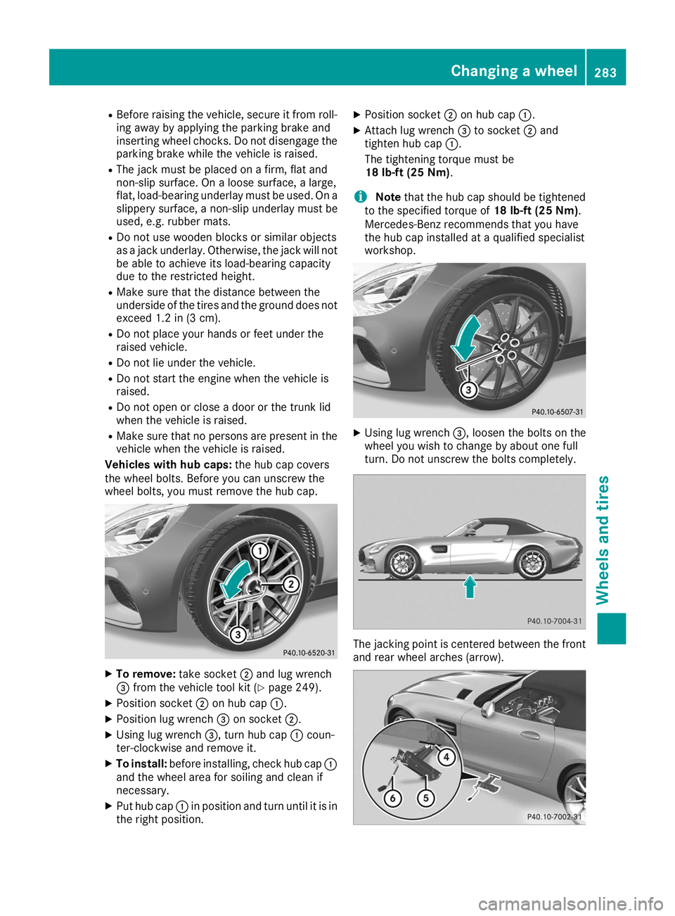
wheel bolts, you must remove the hub cap. X
To remove: take socket0044and lug wrench
0087 from the vehicle tool kit (Y page 249).
X Position socket 0044on hub cap 0043.
X Position lug wrench 0087on socket 0044.
X Using lug wrench 0087, turn hub cap0043coun-
ter-clockwise and remove it.
X To install: before installing, check hub cap 0043
and the wheel area for soiling and clean if
necessary.
X Put hub cap 0043in position and turn until it is in
the right position. X
Position socket 0044on hub cap 0043.
X Attach lug wrench 0087to socket 0044and
tighten hub cap 0043.
The tightening torque must be
18 lb-ft (25 Nm).
i Note
that the hub cap should be tightened
to the specified torque of 18 lb-ft (25 Nm).
Mercedes-Benz recommends that you have
the hub cap installed at a qualified specialist
workshop. X
Using lug wrench 0087, loosen the bolts on the
wheel you wish to change by about one full
turn. Do not unscrew the bolts completely. The jacking point is centered between the front
and rear wheel arches (arrow). Changing a wheel
283Wheels and tires Z
Page 287 of 298
0043
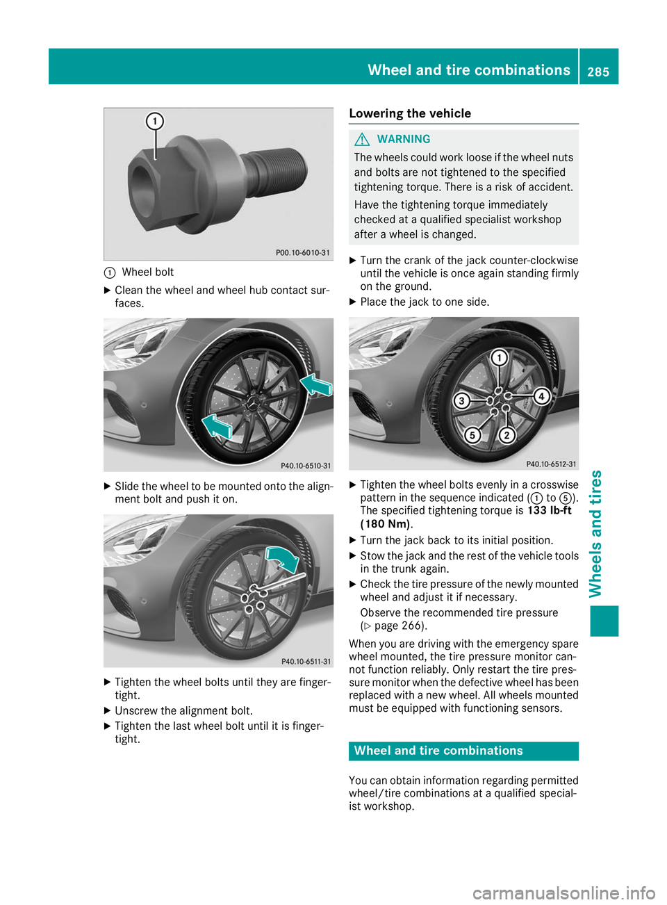
Wheel bolt
X Clean the wheel and wheel hub contact sur-
faces. X
Slide the wheel to be mounted onto the align-
ment bolt and push it on. X
Tighten the wheel bolts until they are finger-
tight.
X Unscrew the alignment bolt.
X Tighten the last wheel bolt until it is finger-
tight. Lowering the vehicle G
WARNING
The wheels could work loose if the wheel nuts and bolts are not tightened to the specified
tightening torque. There is a risk of accident.
Have the tightening torque immediately
checked at a qualified specialist workshop
after a wheel is changed.
X Turn the crank of the jack counter-clockwise
until the vehicle is once again standing firmly
on the ground.
X Place the jack to one side. X
Tighten the wheel bolts evenly in a crosswise
pattern in the sequence indicated (0043 to0083).
The specified tightening torque is 133 lb-ft
(180 Nm).
X Turn the jack back to its initial position.
X Stow the jack and the rest of the vehicle tools
in the trunk again.
X Check the tire pressure of the newly mounted
wheel and adjust it if necessary.
Observe the recommended tire pressure
(Y page 266).
When you are driving with the emergency spare
wheel mounted, the tire pressure monitor can-
not function reliably. Only restart the tire pres-
sure monitor when the defective wheel has been replaced with a new wheel. All wheels mounted
must be equipped with functioning sensors. Wheel and tire combinations
You can obtain information regarding permitted wheel/tire combinations at a qualified special-
ist workshop. Wheel and tire combinations
285Wheels and tires Z