2019 MASERATI LEVANTE parking brake
[x] Cancel search: parking brakePage 292 of 436

Apart from the image at the center of
the display, CC, ACC, HDC, LKA and
HAS systems status is represented by
icons at the top left and right. These
icons remain displayed even when
exiting the “Driver Assist” screen.
The vehicle(s) and horizontal bars
represent the ACC status as ready
(white) or with sensed vehicle ahead
(green); the white, grey or yellow lines
represent the LKA and HAS systems.
The ACC screen can be displayed any
time driver changes system status or
settings. After 5 seconds of ACC
inactivity, the display goes back to last
screen.
ACC Controls and Activation
Conditions The buttons on the LH side of the
steering wheel control the ACC
operations and the other
functions/driver assist systems installed
to this vehicle. 1 Multifunction control shared by all
driver assist functions/systems:
• Press up (indication “RES +”):
increase speed, set current speed
or resume previously set speed
when system is in “cancelled”
status.
• Pushed (indication “CANC”):
cancel the function if it was in
“set” status, going in a ready
condition but remembering the
previous set speed.
• Press down (indication “SET -”):
set speed/decrease speed. 2 Two functions button with ACC
activated:
• ACC Gap: pressed and released;
set the distance to sensed vehicle
ahead as horizontal bars (setting
cycle starts to 3 bars).
• CC On: pressed for 2 seconds
activates the CC system.
• Press it to switch from CC to
ACC.
3 ACC ON/OFF button. If enabled,
pressing this button will disable CC.
4 HAS ON/OFF button with ACC set
only . See "Highway Assist - HAS" in
this section for further details.
NOTE:
Any change made to tire dimensions
affects performance of Adaptive Cruise
Control and Front Collision Warning
(FCW), if equipped.
The ACC is not activated in the
following conditions:
• When braking.
• When parking brake is activated.
• When automatic transmission is in P
(Park), R (Reverse) or N (Neutral).
• When vehicle speed is out of preset
speed range.
• When brakes are overheated.Driving
5
288
Page 295 of 436

accelerator pedal (see “ACC
Operation Before and During Stop”
in this chapter).
• The ACC system maintains set speed
when driving up hill and down hill.
However, a slight speed change on
moderate hills is normal. In addition,
downshifting may occur while
climbing uphill or descending
downhill. This is normal operation
and necessary to maintain set speed.
When driving uphill and downhill,
the ACC system will cancel if the
braking temperature exceeds normal
range.
Temporary Deactivation A soft tap on the brake pedal, pushing
the multifunction control (CANC), or
normal brake pressure while slowing
the vehicle will temporarily deactivate
the ACC without erasing the set speed
memory. The
white light will appear
on the display with below the set
speed.
Conditions for Disabling and
Deactivation Besides the cases specified in the
previous paragraph, the following
conditions will disable the system:
• Anti-Lock Brake (ABS) kicks in. • Transmission lever is not in D (Drive).
• “CORSA” drive mode (TROFEO
version only) is set.
• Ride height is set to “Off Road 1” or
“Off Road 2”.
• The Electronic Stability Control and
the Traction Control System
(ESC/TCS) activate.
• Vehicle parking brake is operated.
• The driver safety belt is unbuckled at
low speed.
• The driver door is ajar at low speed.
• The driver disabled the ESC using the
(ESC OFF) button on central
console.
• The road is too steep both uphill and
downhill at low speed.
The system is deactivated and set
speed is deleted from system memory,
if the ACC ON/OFF button is pressed or
if ignition device is turned to OFF .
Resuming Speed If a speed setting is stored in system
memory, press the multifunction
control (RES +) up and take foot off
the accelerator pedal. The last set
speed will be displayed. WARNING!
The resume function should be used
only when road and traffic conditions
allow it. Resuming a too high or too
low speed for current traffic and road
conditions could cause a harsh vehicle
acceleration or deceleration which
could increase the risk of collisions
and death or serious injury.
Setting the ACC Gap The specified ACC gap can be set by
varying the distance setting among
the four possible options identified by
the number of horizontal bars:
• Maximum (longest) distance: 4 bars.
• Long distance: 3 bars (default
distance).
• Medium distance: 2 bars.
• Short distance: 1 bar.
Using this distance setting and the
vehicle speed, ACC calculates and sets
the gap to the vehicle ahead.
If system does not detect the presence
of any vehicles ahead, only the bars
referred to set distance will be
displayed.
When system detects the presence of a
vehicle ahead, it is displayed in front
of the bars (see example in the figure).Driving
5
291
Page 297 of 436

NOTE:
The displayed warning is a warning
for the driver to take action and does
not necessarily mean that the Forward
Collision Warning (FCW) system is
applying the brakes autonomously.
Overtake Aid When driving with ACC engaged and
following a target vehicle, the system
will provide an additional acceleration
to assist in passing vehicles in front.
This additional acceleration is
triggered when the driver utilizes the
left turn signal to start overtaking. In
locations with left hand drive traffic,
overtake aid is active only when
passing on the left hand side of the
target vehicle.
When a vehicle goes from a location
with left hand drive traffic to a
location with right hand drive traffic,
the ACC system will automatically
detect traffic direction. In this
condition, overtake aid is active only
when passing on the right side of the
target vehicle. This additional
acceleration is triggered when the
driver utilizes the right turn signal to
start overtaking. In this condition the
ACC system will no longer provide
overtake aid on the left side until it determines that the vehicle has moved
back to a location with left hand
drive.
ACC Operation Before and
During Stop If an ACC host vehicle follows a target
vehicle to a standstill, after two or
three seconds the system will not be
able to resume driving the car
autonomously. In this condition, TFT
displays an instruction message pop
up for 5 seconds.
When the ACC system brings the
vehicle to a standstill while following
a target vehicle, the brakes are
released after two or three seconds
after the stop and at the same time
the system inserts the parking brake.
When parking brake engages the ACC
deactivates going to ready state.
At this point the driver must reengage
the system acting on the multifunction
control (RES + or SET -) or alternatively
on the accelerator pedal. While ACC
with Stop is holding your vehicle at a
standstill, if the driver unbuckles the
seatbelt or opens the door, the ESC
system will activate the EPB. During
standstill, ACC system monitors the
occupant detection signals: if the
driver's seatbelt becomes unbuckled, the ACC system shall be cancelled
when the EPB is applied.
WARNING!
• When the ACC system is resumed,
the driver must ensure that there
are no pedestrians, vehicles or
objects in the path of the vehicle.
Failure to follow these warnings can
result in a collision and death or
serious personal injury.
• During the automatic stopping
behind a vehicle in some rare cases
it may happen that the system does
not recognize the rearmost point of
the vehicle ahead but a target under
the vehicle ahead (e.g. the back axis
of a truck with a high loading edge
or a bumper of a vehicle although
overhanging load is hanging over
the vehicle’s rear). In these cases the
system cannot guarantee the
appropriate stopping distance
leading to collision in the worst
case. For this reason the driver has
to be attentive and ready to brake
during automatic stops.Driving
5
293
Page 349 of 436

• Refit the access cover making sure to
engage the two projecting elements
indicated by the arrow fully home
into the bumper.
• Push cover lower end toward
bumper until the two retainers click
in place.
Towing Tips • Before setting out on a trip, check
operation of trailer rear lights and stop lights to ensure you do not
jeopardize other road users' safety.
• Make certain that the load is secured
in the trailer and will not shift
during travel. When trailering cargo
that is not fully secured, dynamic
load shifts can occur that may be
difficult for the driver to control.
• When hauling cargo or towing a
trailer, do not overload your vehicle
or trailer. Overloading can cause a
loss of control, damage to brakes,
driveline, steering, suspension or
tires.
• Safety metal wire must always be
used between your vehicle and
trailer. Always connect the wire to
the hook retainers of the trailer and
vehicle hitch. Cross the wire under
the trailer tongue and allow enough
slack for turning corners.
• Comply with local applicable speed
limits.
• Towing any trailer will increase your
stopping distance. When towing,
you should allow for additional
space between your vehicle and the
vehicle in front of you. Failure to do
so could result in an accident.
• For towing use “Normal” ride
height. • Do not exceed maximum specified
pressure for vehicle and trailer tires.
• Vehicles with trailers should not be
parked on a steep grade. When
parking, put the tow vehicle
transmission in P (Park) and apply
the parking brake on the tow
vehicle. Always, block or "chock" the
trailer wheels.
• Do not use electronic Cruise Control
(CC and/or ACC) when driving on
slopes or when carrying heavy loads.
• The D (Drive) gear must be selected
when towing. The transmission
controls include a drive strategy to
avoid frequent shifting when
towing. However, if frequent
shifting does occur while in D
(Drive), if provided, you can use the
paddle shift switches to manually
select a lower gear.
• Using a lower gear while operating
the vehicle under heavy loading
conditions, will improve
performance and extend
transmission life by reducing
excessive shifting and heat buildup.
This action will also provide better
engine braking.Driving
5
345
Page 351 of 436

6 – In an Emergency ToolKit .............................................. 348
Hazard Warning Flashers ................................. 350
In the Event of an Accident ............................... 350
In case of a Punctured Tire ................................ 351
Emergency Release of the Parking Brake ..................... 356
Transmission Manual Release of P (Park) Position ............... 356
Auxiliary Jump-Start Procedure ............................ 357
Towing a Disabled Vehicle ................................ 360
347
Page 356 of 436

(Continued)
go back to normal operation.
NOTE:
The compact spare wheel is supplied in
aluminum or steel: the pictures show
the one in aluminum.
The compact spare wheel is stored in
the trunk and is supplied deflated in
order to limit the amount of space
occupied. An electric compressor is also
provided for inflating. In the event of
a tire puncture, proceed as follows.
• Stop the vehicle in a place that does
not constitute a danger to traffic and
where the wheel can be changed
safely. The vehicle must be level and
on firm ground.
• Select the P (Park) mode and then
engage manually the electric parking
brake and move the ignition switch
to OFF position.
• If necessary, turn the hazard warning
flashers on and place the warning
triangle (if equipped) at the required
distance.
WARNING!
• The jack should be used on level firm
ground wherever possible. • It is recommended that the wheels
of the vehicle be chocked, and that
no person should remain in a vehicle
that is being jacked.
• If the vehicle has been stopped on a
slope or an uneven surface, place
chocks or other suitable items in
front of or behind the wheels to
stop the vehicle from moving.
• Never start or run the engine with
the vehicle on a jack.
• No person should place any portion
of their body under a vehicle that is
supported by a jack.
• Lift the ground coverage of the
trunk
(see chapter “T ool Kit” in this
section).
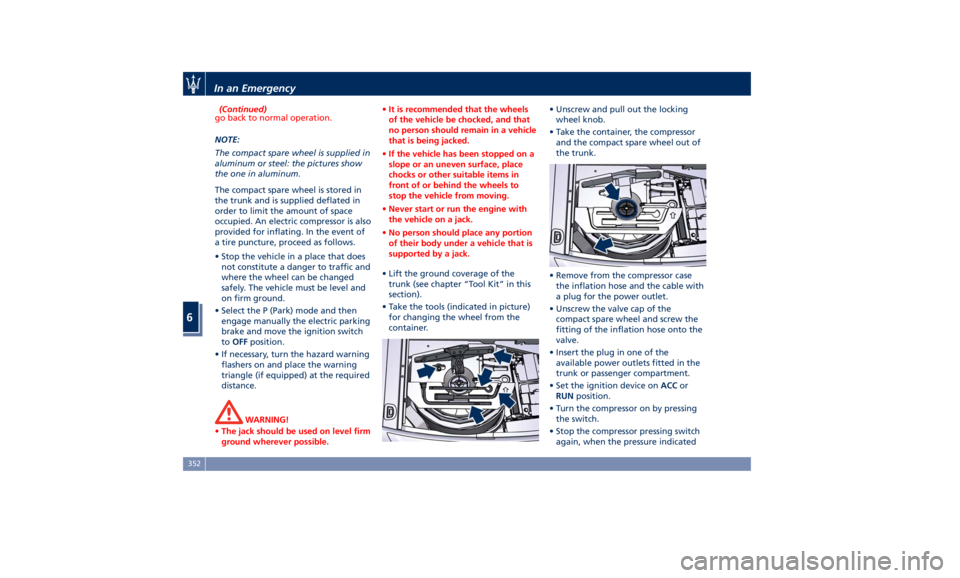
• Take the tools (indicated in picture)
for changing the wheel from the
container. • Unscrew and pull out the locking
wheel knob.
• Take the container, the compressor
and the compact spare wheel out of
the trunk.
• Remove from the compressor case
the inflation hose and the cable with
a plug for the power outlet.
• Unscrew the valve cap of the
compact spare wheel and screw the
fitting of the inflation hose onto the
valve.
• Insert the plug in one of the
available power outlets fitted in the
trunk or passenger compartment.
• Set the ignition device on ACC or
RUN position.
• Turn the compressor on by pressing
the switch.
• Stop the compressor pressing switch
again, when the pressure indicatedIn an Emergency
6
352
Page 360 of 436

Emergency Release of the
Parking Brake In the event the electric parking brake
locks due to a system failure (see
“Parking Brake” in section “Driving”),
it is not possible to move the vehicle,
since the actuator that operates on the
brake pad inside each rear caliper will
lock the rear wheels.
After verifying that the battery is
sufficiently charged (otherwise use an
external power source connected to
the vehicle electric system to operate
the EPB control lever and try to unlock
the parking brake), for moving the
vehicle it is necessary to force the
actuator to release the rear brake
discs. Contact the Authorized Maserati
Dealer to carry out this operation.
WARNING!
If the parking brake has been
activated in manual or automatic
mode and it is not possible to release
it by operating on the lever of the
central console, do not move the
vehicle since rear brake calipers might
be damaged. For more information on vehicle towing see "Towing a Disabled
Vehicle" chapter in this section.
Transmission Manual
Release of P (Park)
Position The manual disengagement of the
shift from P (Park) has the purpose to
allow towing the vehicle if not
normally possible using the shift lever
(such as inability to start the engine).
This procedure is exclusively intended
for emergency situations, only!
WARNING!
Always secure your vehicle by fully
applying the parking brake, before
activating the manual park release.
Activating the manual park release
could allow your vehicle to roll away
if it is not secured by the parking
brake. Activating the manual park
release on an unsecured vehicle could
lead to serious injury or death for
those in or around the vehicle.
The cover that allows the emergency
manual
park release is
located on the
left part of the driver’s foot well.
• Lift the mat on the driver side to
access the cover.
• Slip the cover from its seat.In an Emergency
6
356
Page 361 of 436

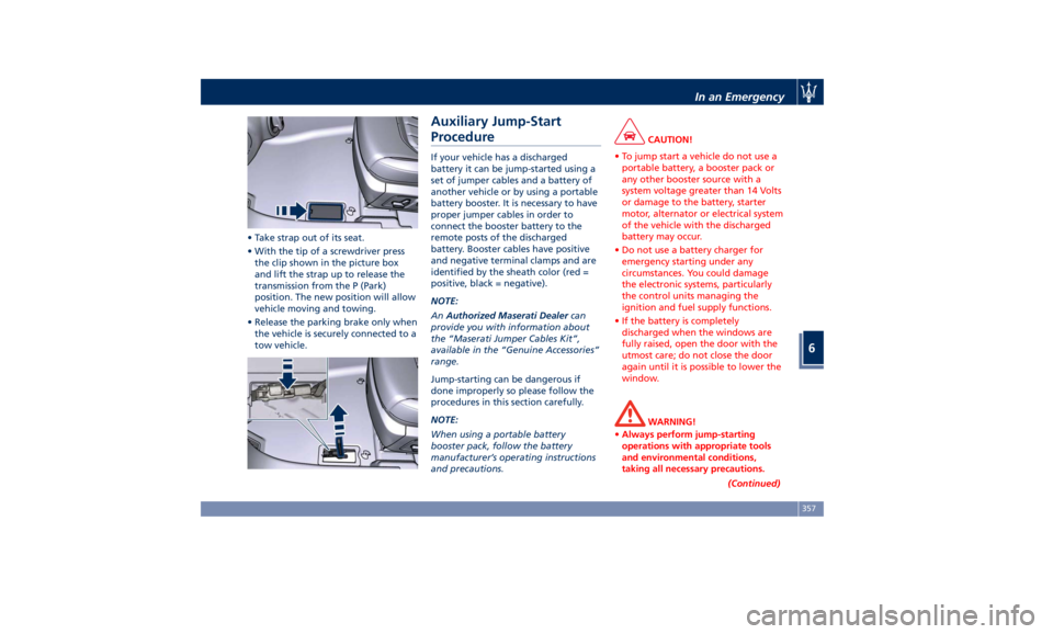
• Take strap out of its seat.
• With the tip of a screwdriver press
the clip shown in the picture box
and lift the strap up to release the
transmission from the P (Park)
position. The new position will allow
vehicle moving and towing.
• Release the parking brake only when
the vehicle is securely connected to a
tow vehicle. Auxiliary Jump-Start
Procedure If your vehicle has a discharged
battery it can be jump-started using a
set of jumper cables and a battery of
another vehicle or by using a portable
battery booster. It is necessary to have
proper jumper cables in order to
connect the booster battery to the
remote posts of the discharged
battery. Booster cables have positive
and negative terminal clamps and are
identified by the sheath color (red =
positive, black = negative).
NOTE:
An Authorized Maserati Dealer can
provide you with information about
the “Maserati Jumper Cables Kit”,
available in the “Genuine Accessories”
range.
Jump-starting can be dangerous if
done improperly so please follow the
procedures in this section carefully.
NOTE:
When using a portable battery
booster pack, follow the battery
manufacturer’s operating instructions
and precautions. CAUTION!
• To jump start a vehicle do not use a
portable battery, a booster pack or
any other booster source with a
system voltage greater than 14 Volts
or damage to the battery, starter
motor, alternator or electrical system
of the vehicle with the discharged
battery may occur.
• Do not use a battery charger for
emergency starting under any
circumstances. You could damage
the electronic systems, particularly
the control units managing the
ignition and fuel supply functions.
• If the battery is completely
discharged when the windows are
fully raised, open the door with the
utmost care; do not close the door
again until it is possible to lower the
window.
WARNING!
• Always perform jump-starting
operations with appropriate tools
and environmental conditions,
taking all necessary precautions.
(Continued)In an Emergency
6
357