2019 MASERATI LEVANTE wheel torque
[x] Cancel search: wheel torquePage 305 of 436

Lane Keeping Assist - LKA
(optional, with ACC only) This system was designed especially
for highway or freeway driving, to
reduce the risk that the vehicle, under
particular circumstances, accidentally
departs from the lane in use. When
this happens, graphic instructions on
instrument cluster display together
with steering torque application and
steering wheel vibration (depending
on the distance to the line) warn the
driver that the vehicle is going out of
the lane and initiate a steering
maneuver to try to prevent the lane
exit.
To detect lane lines, the system uses
the forward-facing camera behind of
the rear-view mirror, which is the same
one used also by the lighting system
to manage the automatic high beams.
The logic core is in the front radar.
LKA system remembers the condition
it was in before turning off the
vehicle.
Refer to “MTC+ "Controls" Screen” in
section “Dashboard Instruments and
Controls” for further information. NOTE:
In case of wet road or raining
conditions the function could be
disabled by the system in order to
minimize the risks.
Speed Range of Use Speed mph (km/h)
Minimum 37 (60)
Engaged/activated 37 (60)
Maximum 112 (180)
Customized Settings LKA is configurable by the driver in
order to maximize its efficiency based
on the driver driving style and the
expectation of the system, reducing at
the same time the possible
invasiveness.
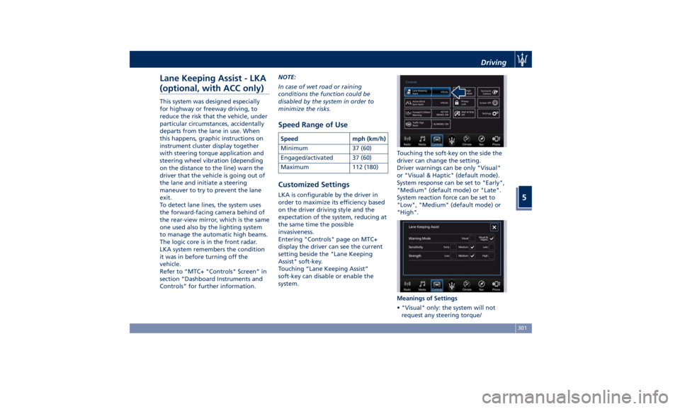
Entering "Controls" page on MTC+
display the driver can see the current
setting beside the "Lane Keeping
Assist" soft-key.
Touching “Lane Keeping Assist”
soft-key can disable or enable the
system. Touching the soft-key on the side the
driver can change the setting.
Driver warnings can be only "Visual"
or "Visual & Haptic" (default mode).
System response can be set to "Early",
"Medium" (default mode) or "Late".
System reaction force can be set to
"Low", "Medium" (default mode) or
"High".
Meanings of Settings
• "Visual" only: the system will not
request any steering torque/Driving
5
301
Page 306 of 436

vibration to correct the car trajectory.
The system will only show on the TFT
display when the vehicle is passing
the lane.
• "Visual & Haptic": the system will
apply steering torque when lane
departure is detected while showing
at the same time the proper cluster
indication, adding to this steering
vibration when the departure is very
imminent.
When "Visual & Haptic" is selected and
LKA is enabled then the following
menu will be used by the system.
• "LKA Sensitivity": it tunes the
distance to the lane boundary where
the system will start to apply steering
torque.
• "LKA Strength": it tunes the steering
torque value to have a stronger or
weaker trajectory correction/
deviation.
WARNING!
In rare cases, Lane Keeping Assist
(LKA) may make an inappropriate
steering torque application. LKA may
be interrupted at any time counter
steering. Lack of attention may lead to
serious injury or death. System Availability The ADAS systems (LKA, CC, ACC, FCW
and HAS) help the driver while driving.
These systems can be set and
monitored simultaneously on the
display, after opening “Driver Assist”
menu (see paragraph “TFT Display:
Menus and Settings” under
“Instrument Cluster” in section
“Dashboard Instruments and
Controls”).
LKA is designed for an attentive driver;
therefore the system is available only
when his/her hands are on the steering
wheel or with hands off only for a very
limited amount of time. When the
system is enabled it will trigger cluster
warning in case at least one hand is
not detected on the steering wheel.
The torque application as well as the
vibration are suppressed/inhibited in
case of: high driver torque in the
steering wheel, high lateral
acceleration, trailer connected to the
proper control module, hands not on
the steering wheel detected for more
than a certain time.
High dynamic driving behaviors,
driving on the lane boundary or
driving off course will prevent the
function from working. FCW braking
and stability system interventions (ESC, ABS) will also prevent the system from
operating. Changing lane results in
system inhibition for a certain time. In
addition, the driver must respect some
road characteristics such as
minimum-maximum width, lanes
clearly defined by two lane boundaries
and for a limited time, the presence of
at least one lane boundary.
NOTE:
• In case of wet road or raining
conditions the function could be
disabled by the system in order to
minimize the risks.
• With lane boundaries it is mainly
referred to painted lines,
nevertheless the system in good
conditions might properly recognize
as valid lane boundaries also other
types (for example road edges, curbs,
etc..).
Being this function used to prevent
unintentional lane change/lane drift, it
will be temporary suppressed/inhibited
by a turn indicator activation,
therefore, graphic warning, steering
torque application and vibration will
be terminated. In this condition in case
of a vehicle detected by the Blind Spot
Assist (BSA) system in the covered area
on the proper side, there can be theDriving
5
302
Page 308 of 436

The icons that represent the status of
the ADAS systems remain displayed
even when you exit the “Driver Assist”
screen.
System Limitations Because of physical limits, in order to
properly operate, the system needs
good visibility (it might not work or
not properly operate in case of heavy rain, snow, wet roads, fog, direct sun
on the camera, etc.).
NOTE:
• The presence of the hands on the
steering wheel is detected by a logic
combination of a capacitive sensor
installed in the steering wheel and
the measured applied torque at the
steering column. This leads to a more
robust hands detection when hands
are actually on the steering wheel (at
least one).
• The sensors are not able to detect
the presence of the hands on the
steering wheel areas covered in
wood, plastic bezels or carbon inserts
(where present).
Sharp turns, slopes and change in
slopes, poor lane boundaries, as well
as construction areas and all the
scenario described in this paragraph
may challenge the system, therefore
be always ready to prevent any
unexpected behaviour of the car.
Damaged front bumper, windshield
replaced without proper technical
intervention may also lead to system
malfunction or system unavailability.
Other conditions such as fault, but not
explicitly indicated here may also prevent/interrupt the system
intervention.
WARNING!
If the driver fails to adapt his/her
driving style, Lane Keeping Assist
(LKA) can neither reduce the risk of an
accident nor override the laws of
physics. It cannot take into account
road, weather or traffic conditions.
Active LKA is only an aid. Driver is
always responsible for the distance to
the vehicle in front, for vehicle speed,
for braking in good time and for
staying in lane.
System in Fault When the LKA cannot properly
operate due to a fault of its
components or because the windshield
in front of the forward facing camera
is dirty, the amber light and/or the
corresponding message will be
displayed.Non-Driver Assist PageDriving
5
304
Page 314 of 436

System is Faulty
The BSA system cannot properly
operate due to a fault of its
components, or because the area on
the rear bumper fascia where the
radar sensors are located is dirty. In
these cases the amber warning light
and the related message will be
displayed on the instrument cluster.
In these cases avoid using the system
and have the vehicle inspected at an
Authorized Maserati Dealer .
Radar Device - Regulatory
Information The “Regulatory Information” for all
the radio frequency and radar devices
can be consulted by accessing the
"Services" section on the website
www.maserati.com. Active Blind Spot Assist -
ABSA (optional, with ACC
only) ABSA system is only available on
vehicles equipped with ACC system
and represents an addition to the BSA
previously described (see chapter
"Blind Spot Assist - BSA" of this
section).
ABSA adds to the BSA the possibility in
certain circumstances to avoid and or
mitigate side collisions with vehicles
proceeding in the adjacent lanes by
changing the car trajectory in order to
try to keep it inside the detected/
estimated lane. A steering wheel
vibration is used as further feedback to
warn the driver that the lane change is
not safe.
The main logic core is the front radar,
whereas the sense inputs are the
radars on the rear bumper fascia used
for sensing the presence of vehicle in
the blind spot areas and the forward
facing camera placed behind the
internal rear-view mirror that instead
is used for lane detection and
estimation.
ABSA is designed to help the driver to
avoid mitigate a collision. Torque and
vibration application is however available in the 37 - 112 mph (60 -
180 km/h) speed interval. All the speed
thresholds related to the BSA remain
still valid, since ABSA as mentioned is
BSA extension.
ABSA is intended as a “hands-on”
function meaning that the driver is
required to stay engaged in the
driving all the time with his/her hands
on the steering wheel, in case hands
are not on the steering wheel for a
certain time there cannot be any
steering torque application vibration
included.
System Availability ABSA is designed for an attentive
driver therefore the system is available
only when his/her hands are on the
steering wheel or with hands off for a
very limited amount of time. When the
system is enabled, it will trigger cluster
warning in case at least one hand is
not detected on the steering wheel.
The torque application as well as the
vibration are suppressed/inhibited in
case of: high driver torque in the
steering wheel, high lateral
acceleration, hands not on the steering
wheel detected for more than a
certain time.
Highly dynamic behaviours, driving on
the lane boundary, off course willDriving
5
310
Page 316 of 436

System sensitivity can be set to “Early”,
“Medium” (default mode) or “Late”.
System strength can be set to "Low",
"Medium" (default mode) or "High".
NOTE:
The ABSA system will store the current
operating mode when the vehicle is
shut off. Each time the vehicle is
started, the previously-stored mode
will be recalled and used.
Meanings of Settings
When "Visual & Haptic" is selected and
of course ABSA is enabled, then two
following menus will be used by the
system.
• ABSA "Sensitivity": it tunes the
distance to the lane boundary where
the system will start to apply steering
torque. • ABSA “Strength": it tunes the
steering torque value to have a
stronger or weaker trajectory
correction/deviation.
Blind Spot Assist in "Visual & Haptic"
Mode
When the system is on and configured
“Visual & Haptic” then the ABSA is
enabled and to the conventional visual
warnings is added the steering torque
and vibration.
When operating in this mode, the
system will provide a visual alert in the
appropriate outside rear-view mirror
when it detects a vehicle or an object
in the detection areas monitored by its
sensors. In case of turn indicator
activation on the appropriate side, the
system will react with a torque on the
steering wheel to try to prevent the
lane change and therefore to
avoid/mitigate the collision. The
torque on the steering is applied when
the car is very close to the lane
boundary as a further feedback to
warn the driver of the unsafe
maneuver.
NOTE:
• The steering torque is not supplied if
the system is not able to estimate a
lane and if the turn indicator from
the appropriate side is not inserted. • The presence of the hands on the
steering wheel is detected by a logic
combination of a capacitive sensor
installed in the steering wheel and
the measured applied torque at the
steering column. This leads to a more
robust hands detection.
WARNING!
• Risk of accident despite steering
torque application of Active Blind
Spot Assist (ABSA).
• A course-correcting steering torque
application cannot always prevent a
collision.
• The driver is always required to
steer, brake or accelerate themself,
especially if ABSA warns or makes a
course correcting steer intervention.
• Always maintain a safe distance at
the sides.
• Steering torque application may be
interrupted at any time by counter
steering by the driver.
RCP - Rear Cross Path
Operation RCP operation is the same as described
in chapter "Blind Spot Assist - BSA".Driving
5
312
Page 322 of 436

• Press the HAS enable button on
the steering wheel.
• Begin steering manually.
• Press brake pedal.
• Turn off ACC.
• Unbuckle the driver’s seat belt.
• Press ACC Gap button for two
seconds to enable CC system.
• Shift out of the (D) Drive gear.
• Enter an Autonomous Emergency
Braking (AEB) event (See chapter
"Forward Collision Warning - FCW"
in this section).
• Turn signal activated.
System Cancellation The HAS system will cancel (without
driver intervention) if either of the
following actions occur:
• Curve that is too tight.
• When leaving the grip of the hands
on the steering wheel.
• Vehicle exits the highway or limited
access freeway.
• Lane line markers aren’t detected by
the forward facing camera.
• Any ADAS system faults.
• ACC cancellation.
• Vehicle speed exceeds the maximum
limit. • Lateral accelerations exceeds the
limits.
NOTE:
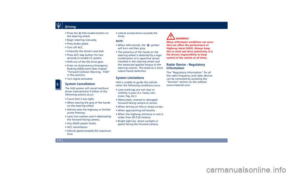
• When HAS cancels, the
symbol
will turn red then grey.
• The presence of the hands on the
steering wheel is detected by a logic
combination of a capacitive sensor
installed in the steering wheel and
the measured applied torque at the
steering column. This leads to a more
robust hands detection.
System Limitations HAS is unable to guide the vehicle
when the following conditions occur.
• Lane markings are not clear or
visibility is poor (i.e. heavy rain,
snow, fog, etc.).
• Obstructed, covered or damaged
forward-facing camera or sensor.
• When driving on hills or sharp curves.
• When approaching toll booths.
• When the highway entrance or exit is
wider than 20 ft (6 meters).
• Bright light (ex. direct sunlight or
glare) facing the forward camera. WARNING!
Many unforeseen conditions can occur
that can affect the performance of
Highway Assist (HAS). Always keep
this in mind and drive attentively. It is
the drivers responsibility to keep
control of the vehicle at all times.
Radar Device - Regulatory
Information The “Regulatory Information” for all
the radio frequency and radar devices
can be consulted by accessing the
"Services" section on the website
www.maserati.com.Driving
5
318
Page 358 of 436

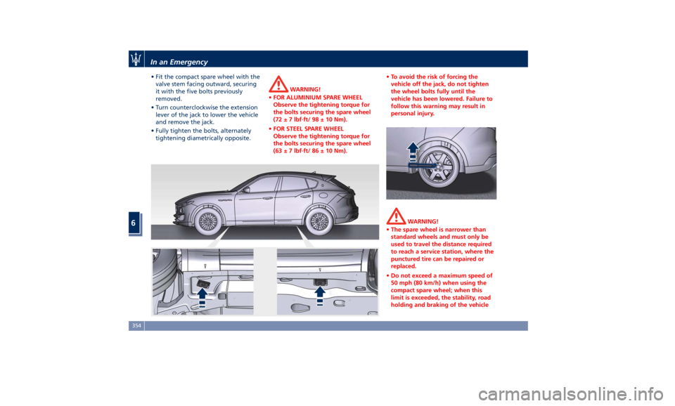
• Fit the compact spare wheel with the
valve stem facing outward, securing
it with the five bolts previously
removed.
• Turn counterclockwise the extension
lever of the jack to lower the vehicle
and remove the jack.
• Fully tighten the bolts, alternately
tightening diametrically opposite. WARNING!
• FOR ALUMINIUM SPARE WHEEL
Observe the tightening torque for
the bolts securing the spare wheel
(72 ± 7 lbf·ft/ 98 ± 10 Nm).
• FOR STEEL SPARE WHEEL
Observe the tightening torque for
the bolts securing the spare wheel
(63 ± 7 lbf·ft/ 86 ± 10 Nm). • To avoid the risk of forcing the
vehicle off the jack, do not tighten
the wheel bolts fully until the
vehicle has been lowered. Failure to
follow this warning may result in
personal injury.
WARNING!
• The spare wheel is narrower than
standard wheels and must only be
used to travel the distance required
to reach a service station, where the
punctured tire can be repaired or
replaced.
• Do not exceed a maximum speed of
50 mph (80 km/h) when using the
compact spare wheel; when this
limit is exceeded, the stability, road
holding and braking of the vehicleIn an Emergency
6
354
Page 359 of 436

will be compromised. Avoid
accelerating to full speed, heavy
braking and fast cornering.
• The compact spare wheel must be
inflated to the recommended tire
pressure (see “Tire Inflation
Pressure” in section “Features and
Specifications”).
• For safety reasons, it is absolutely
forbidden to drive with more than
one compact spare wheel fitted on
the vehicle.
• Snow chains cannot be fitted on the
compact spare wheel.
• The spare wheel can travel a
maximum of 1,800 mi (3.000 km).
To Refit the Standard Wheel with
Repair
ed or Replaced Tire
• Following the procedure and the
caution described above, raise the
vehicle and remove the compact
spare wheel reusing the supplied
wrench with adapter, suitably
extended.
• Fit the standard wheel with repaired
or replaced tire.
• Tighten the original bolts on the
wheel.
• Lower the vehicle and remove the
jack. • Fully tighten the bolts, alternately
tightening diametrically opposite.
WARNING!
Observe the tightening torque for the
bolts securing the wheels (72 ± 7 lbf·ft
/ 98 ± 10 Nm).
• Reassemble the center cover (if
provided)
on the wheel
rim.
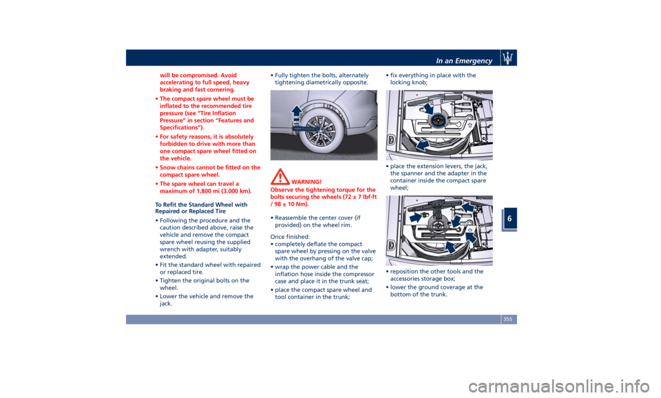
Once finished:
• completely deflate the compact
spare wheel by pressing on the valve
with the overhang of the valve cap;
• wrap the power cable and the
inflation hose inside the compressor
case and place it in the trunk seat;
• place the compact spare wheel and
tool container in the trunk; • fix everything in place with the
locking knob;
• place the extension levers, the jack,
the spanner and the adapter in the
container inside the compact spare
wheel;
• reposition the other tools and the
accessories storage box;
• lower the ground coverage at the
bottom of the trunk.In an Emergency
6
355