2019 MASERATI LEVANTE transmission
[x] Cancel search: transmissionPage 138 of 436
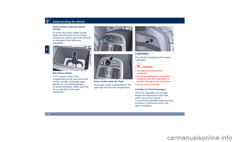
Power Outlets inside the Central
Console
To access the power outlet located
inside the glove box of the central
console you need to open the half-lids
as indicated in the following
paragraph.
Rear Power Outlets
A 12 V power outlet in the
compartment at the rear end of the
central console, is available upon
request for rear seat passengers.
To access the power outlet, push the
lid as indicated: it will open
completely. Power Outlet inside the Trunk
The power outlet is positioned on the
right side of the trunk compartment. Cupholders The vehicle is equipped with several
cupholders.
CAUTION!
• Use light and shatterproof
containers.
• Do not forcefully push unsuitable
containers into the cupholders to
prevent damage to the containers.
• Do not store hot drinks.
Cuholders for Front Passengers
The
front cupholders are located
beside the transmission lever and
within the central console.
To access the cupholder, push the cover
as shown in the picture and it will
open completely.Understanding the Vehicle
3
134
Page 141 of 436
for extended periods of time: extreme
temperatures and humidity can occur
in the vehicle.
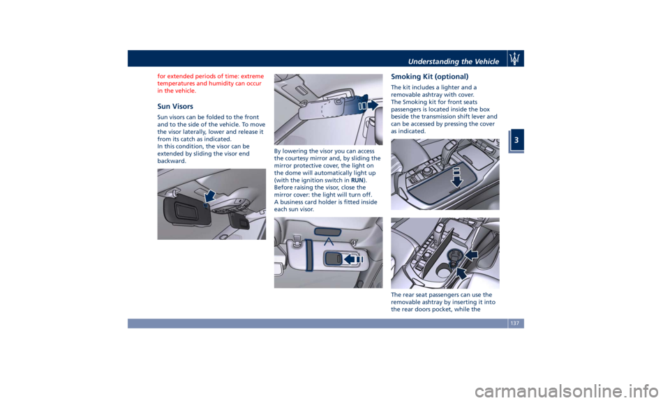
Sun Visors Sun visors can be folded to the front
and to the side of the vehicle. To move
the visor laterally, lower and release it
from its catch as indicated.
In this condition, the visor can be
extended by sliding the visor end
backward. By lowering the visor you can access
the courtesy mirror and, by sliding the
mirror protective cover, the light on
the dome will automatically light up
(with the ignition switch in RUN ).
Before raising the visor, close the
mirror cover: the light will turn off.
A business card holder is fitted inside
each sun visor. Smoking Kit (optional) The kit includes a lighter and a
removable ashtray with cover.
The Smoking kit for front seats
passengers is located inside the box
beside the transmission shift lever and
can be accessed by pressing the cover
as indicated.
The rear seat passengers can use the
removable ashtray by inserting it into
the rear doors pocket, while theUnderstanding the Vehicle
3
137
Page 155 of 436
For more efficient programming and
accurate transmission of the
radio-frequency signal it is
recommended that a new battery be
placed in the hand-held transmitter of
the device that is being programmed
to the HomeLink ®
system.
Before starting programming it is
necessary to erase the standard codes
memorized on the HomeLink ®
device
during the production phase. To erase
such codes:
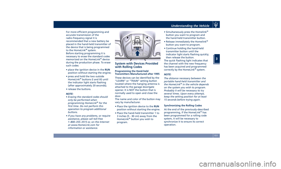
• place the ignition device in the RUN
position without starting the engine;
• press and hold the two outside
HomeLink ®
buttons (I and III) until
the indicator light starts flashing
(after approximately 20 seconds);
• release the buttons.
NOTE:
• Erasing the standard codes should
only be performed when
programming HomeLink ®
for the
first time. Do not perform this
operation to program additional
buttons.
• If you have any problems, or require
assistance, please call toll-free
1–800–355–3515 or, on the Internet
at www.HomeLink.com for
information or assistance. System with Devices Provided
with Rolling Codes Programming the Hand-held
Transmitters Manufactured after 1995
These devices can be identified by the
“LEARN” or “TRAIN” setting button
located where the hanging antenna is
attached to the garage door/gate
opener. It is NOT the button that is
normally used to open and close the
door.
The name and color of the button may
vary by manufacturer.
• Place the ignition device to the RUN
position without starting the engine.
• Place the hand-held transmitter 1 to
3 inches (5 - 30 cm) away from the
HomeLink ®
button you wish to
program. • Simultaneously press the Homelink ®
button you want to program and
the hand-held transmitter button.
• Release immediately the Homelink ®
button you want to program.
• Continue holding the hand-held
transmitter button until the
indicator light starts flashing quickly;
then release the button.
The quick flashing light indicates that
the channel with the new frequency
has been acquired and programmed
correctly by the HomeLink ®
system.
NOTE:
The distance necessary between the
portable hand-held transmitter and
the HomeLink ®
in the vehicle depends
on the system you wish to program.
Probably it will be necessary to try
several times. Upon every attempt,
keep the setting position for at least
15 seconds before trying again.
Synchronizing the Rolling Codes
At the end of the previously-described
programming, if the HomeLink ®
has
been programmed for a rolling code
system, it will be necessary to
synchronize it to ensure its correct
operation.Understanding the Vehicle
3
151
Page 165 of 436

Warning and Indicator Lights
on Analog Instruments Telltales on Speedometer
The following telltales are displayed
on the speedometer, and related
messages are visible for 5 seconds on
the central sector of the display, unless
otherwise indicated (see “TFT Display:
Warning/Indicator Lights of Set
Modes/Functions” paragraph in this
chapter).
Malfunction Indicator Light (MIL)
The Malfunction Indicator
Light (MIL) is part of an
onboard diagnostic system
that monitors engine and
automatic transmission control
systems.
Under normal conditions, this
indicator light should switch on when
the ignition switch is in RUN position and switch off soon after the engine is
started (the MIL does not shut off
immediately).
This is a sign of the indicator light
working properly. If the indicator
remains illuminated or switches on
while driving, there is a failure in the
fuel supply/ignition and emission
control systems.
The failure could cause high exhaust
emissions, loss of performance, poor
vehicle handling and high
consumption levels.
Should this occur, proceed with
caution to your Authorized Maserati
Dealer without heavy throttle
application or driving at high speeds.
Obey all applicable local traffic
regulations.
The indicator light will go out if the
problem is no longer present.
The error will be registered by the
system in any case.
CAUTION!
• When the ignition switch is in the
RUN position and if the indicator
light does not switch on or if it
switches on while driving, contact an
Authorized Maserati Dealer as soon
as possible. • Prolonged driving with the MIL on
could cause damage to the engine
control system. It also could affect
fuel economy and drivability. If the
MIL is flashing, severe catalytic
converter damage and power loss
will soon occur. Immediate service is
required. In addition, the OBDII
system incorporates a diagnostic
connector that can be interfaced
using diagnostic equipment. This
makes it possible to read the error
codes stored in the control unit,
together with a set of specific
parameters for the engine operation
diagnostic cycle, for compliance with
CARB & EPA OBDII regulations.
Left Turn Signal Indicator Light
The
indicator lights up when
the left turn signals or the
hazard flashers are turned on.
The indicator light will flash at
the same frequency of the turn signals
and is controlled by the multifunction
lever behind the steering wheel.
If the vehicle electronics sense that the
vehicle drives for more than 1 mile
(1.6 km) with either turn signal on, a
continuous sound will alert the driver
to turn the signal off.Dashboard Instruments and Controls
4
161
Page 171 of 436

sector 23, only the main menu number
and the scroll arrows remain displayed
in the sector 3 , left side.
Within a submenu, press and release
the switch in the
and arrow
directions to scroll the menu.
Press the
button to return to the
main menu from an item of interest or
from an information screen.
Main Menu & Submenu Content
Overview
1. MAIN MENU
• View speed in mph or km/h
2. VEHICLE INFO
• Tire Pressure
• Transmission Temperature
• Oil Temperature
• Oil Pressure
• Battery Voltage
• Maintenance 3. DRIVE MODE
• Drive Mode - Ride Height - Torque
Distribution - Powertrain status - ESC
status - Suspension stiffness status
4. Driver Assist (if equipped)
• Shows the status of any active driver
assist systems: CC, ACC, LKA and
HAS. Graphics in the main area of
TFT display only refer to ACC, LKA
and HAS systems
• LKA (LaneSense) status
5. FUEL ECONOMY
• Average, Range, Current gage
6. TRIP
• Trip A: Average, Avg. speed, Elapsed
time, Distance
• Trip B: Average, Avg. speed, Elapsed
time, Distance
7. START&STOP
• Messages relating to the Start&Stop
function
8. AUDIO
• Information concerning audio status
according to current media source,
track and station.
• Information on phone incoming call.
9. STORED MESSAGES
10. VEHICLE SETTINGS • Speed Warning: enables, disables or
sets the speed limit represented in
the dynamic icon on the TFT display
• Auto apply Off/On of the Electric
Parking Brake
• Interior Lighting
– Backlighting
– Ambient Lighting
• SCREEN SETUP
– Upper Left
– Upper Right
– Main Menu: Line 1
– Main Menu: Line 2
– Main Menu: Line 3
– MPH km/h Display On/Off
– Main Menu Navigation
– Outline Coloring
– Key-On Display
– Key-Off Display
– Defaults
Messages on Main Display Area
The main display area also displays
"pop up" messages. These pop up
messages fall into several categories:
• Five-Second Stored Messages
When the appropriate conditions
occur, this type of message appears
on the main display area for five
seconds and then returns to the
previous screen. Most of the
messages of this type are thenDashboard Instruments and Controls
4
167
Page 173 of 436
• The distance indicated under the
road name is expressed in the unit of
measure set by the user.
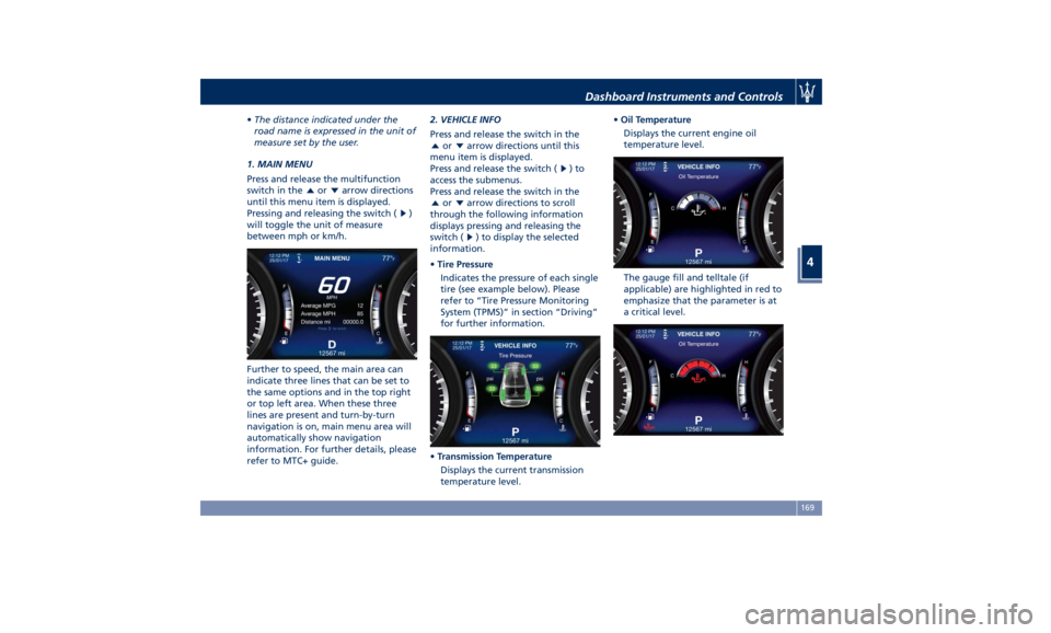
1. MAIN MENU
Press and release the multifunction
switch in the
or arrow directions
until this menu item is displayed.
Pressing and releasing the switch (
)
will toggle the unit of measure
between mph or km/h.
Further to speed, the main area can
indicate three lines that can be set to
the same options and in the top right
or top left area. When these three
lines are present and turn-by-turn
navigation is on, main menu area will
automatically show navigation
information. For further details, please
refer to MTC+ guide. 2. VEHICLE INFO
Press and release the switch in the
or arrow directions until this
menu item is displayed.
Press and release the switch (
)to
access the submenus.
Press and release the switch in the
or arrow directions to scroll
through the following information
displays pressing and releasing the
switch (
) to display the selected
information.
• Tire Pressure
Indicates the pressure of each single
tire (see example below). Please
refer to “Tire Pressure Monitoring
System (TPMS)” in section “Driving”
for further information.
• Transmission Temperature
Displays the current transmission
temperature level. • Oil Temperature
Displays the current engine oil
temperature level.
The gauge fill and telltale (if
applicable) are highlighted in red to
emphasize that the parameter is at
a critical level.Dashboard Instruments and Controls
4
169
Page 174 of 436

NOTE:
This strategy is also applicable in the
Transmission Temperature and Oil
Pressure information screen.
• Oil Pressure
Displays the current engine oil
pressure level.
• Battery Voltage
Displays the current battery voltage.
• Maintenance (service)
Displays mileage and days remaining
to the execution of scheduled
maintenance service.
Press and release the
button to
return to the main menu.
3. DRIVE MODE
Press and release the switch in the
or arrow directions until this
menu item is displayed. The screen graphically shows the Drive Mode: OFF
ROAD, I.C.E., NORMAL, SPORT, CORSA
(TROFEO version only) and
(Suspension) set by the user through
the relevant controls.
The display main area will show
vehicle image with parameters and
color-coded components affected by
the selected drive mode.
The image will show the following
parameters:
• current ground clearance indicated
in front of vehicle and on a specific
indicator on top right corner;
• torque distribution percentage
indicated under the arrow in front of
the wheels;
• selected drive mode (in the example
shown: I.C.E.).
For any color-coded components, color
depends on settings of:
• ESC: identified by wheel color.
• PowerTrain: identified by engine +
transmission unit color.
• Suspension
: identified by the
color of the four shock absorbers. For every drive mode, function (ESC,
PowerTrain and Suspension) and color
of the components shown are matched
as follows:
NOTE:
To set drive parameters according to
own needs and path, refer to chapter
“Drive Mode” and “Off-road Drive” in
section “Driving”.
Press and release the
button to
return to the main menu.Dashboard Instruments and Controls
4
170
Page 179 of 436
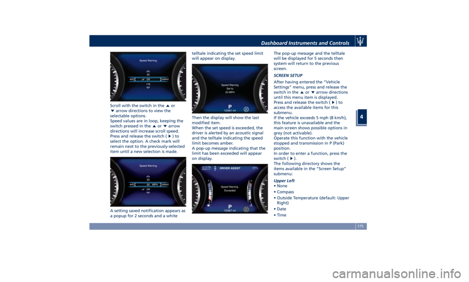
Scroll with the switch in the or
arrow directions to view the
selectable options.
Speed values are in loop, keeping the
switch pressed in the
or arrow
directions will increase scroll speed.
Press and release the switch (
)to
select the option. A check mark will
remain next to the previously-selected
item until a new selection is made.
A setting saved notification appears as
a popup for 2 seconds and a white telltale indicating the set speed limit
will appear on display.
Then the display will show the last
modified item.
When the set speed is exceeded, the
driver is alerted by an acoustic signal
and the telltale indicating the speed
limit becomes amber.
A pop-up message indicating that the
limit has been exceeded will appear
on display. The pop-up message and the telltale
will be displayed for 5 seconds then
system will return to the previous
screen.
SCREEN SETUP
After having entered the “Vehicle
Settings” menu, press and release the
switch in the
or arrow directions
until this menu item is displayed.
Press and release the switch (
)to
access the available items for this
submenu.
If the vehicle exceeds 5 mph (8 km/h),
this feature is unavailable and the
main screen shows possible options in
grey (not activable).
Operate this function with the vehicle
stopped and transmission in P (Park)
position.
In order to enter a function, press the
switch (
).
The following directory shows the
items available in the “Screen Setup”
submenu:
Upper Left
• None
• Compass
• Outside Temperature (default: Upper
Right)
• Date
• TimeDashboard Instruments and Controls
4
175