2019 MASERATI LEVANTE key battery
[x] Cancel search: key batteryPage 54 of 436
C. Sunshade fully rolled down
(“DOWN” position) and Window
completely open (“DOWN” position)
• Pulling the control to 1 or 2 detent:
the window closes partially or
completely and the sunshade
remains rolled.
• Pressing the control to 1 or 2 detent:
no action (“NOP”).
Teaching Cycle
After battery disconnection, the
following teaching cycle is required to
store the limit positions the sunshades.
Use the controls on the rear doors to
move the sunshades.
• With glass closed, lift rear sunshade
control on driver side for a few
seconds. It is not necessary that the
sunshade reaches its upper limit.
• Reverse the sunshade movement by
pressing the control downwards.
Once the lower limit is reached, press
and hold the control for at least 10
seconds. This action allows setting
the control unit in initialisation
status.
• Release the movement command.
• Within maximum 15 seconds:
• Press once the control downwards
(first or second detent). In this way
the control unit stores the lower limit position. During this
operation a slight click of the
sunshade motor that switches to
mechanical lock condition can be
heard.
• Lift the control and hold it up until
the sunshade completes its
upstroke and reaches the car body
pillar, fully home. Once the upper
limit stop is reached, the sunshade
will move downwards for approx.
2-3 millimetres and the control unit
will store this height as the upper
limit. Now the teaching of the
driver side rear sunshade is
complete.
• Repeat the same operations for the
passenger side rear sunshade to
complete the teaching procedure.Power Liftgate Operation The power liftgate can be operated
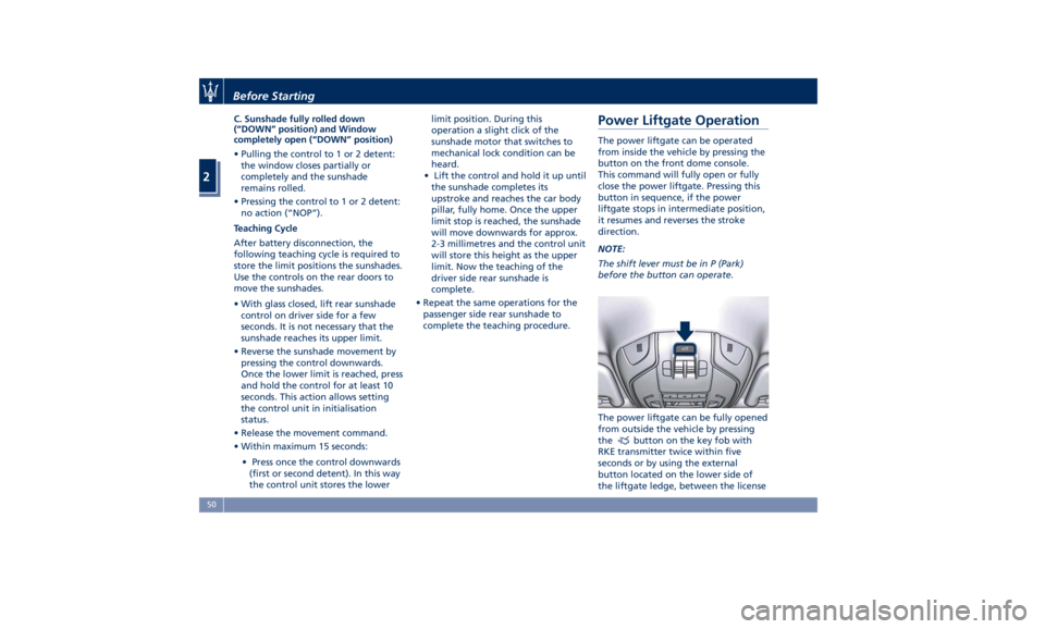
from inside the vehicle by pressing the
button on the front dome console.
This command will fully open or fully
close the power liftgate. Pressing this
button in sequence, if the power
liftgate stops in intermediate position,
it resumes and reverses the stroke
direction.
NOTE:
The shift lever must be in P (Park)
before the button can operate.
The power liftgate can be fully opened
from outside the vehicle by pressing
the
button on the key fob with
RKE transmitter twice within five
seconds or by using the external
button located on the lower side of
the liftgate ledge, between the licenseBefore Starting
2
50
Page 59 of 436

tailpipes as they can reach high
temperatures and, in case of contact,
they can cause severe burns.
• When it is not necessary to open the
power liftgate with the Hands free
mode, make sure the key fob is
outside the range of use (3.3 ft/1 m).
Otherwise, the power liftgate can
be opened accidentally by an
unintentional movement of the
foot.
In order for the sensors to detect your
foot
movement, move your foot
towards the vehicle rather than
sideways and immediately pull it back:
from this moment, the power liftgate
will activate within two seconds.
If closed, with the foot movement the
power liftgate will:
• unlock and completely open;
• after another kick, will stop; • after another kick, will reverse its
movement and completely close
unless stopped again.
If open, with the foot movement the
power liftgate will:
• completely close but not lock;
• another kick before the completed
closing can stop the movement;
• if the movement was stopped
another kick operation will invert a
complete opening.
NOTE:
• If your foot movement fails to
activate the power liftgate
movement, wiggling your foot
under the bumper will not help.
Repeat the whole kick movement.
• In particular situations, external
factors affecting the sensor area may
trigger the Hands free power
liftgate release feature. For example,
when washing the vehicle, a water
jet aimed at the sensor area may
trigger the Hands free power
liftgate release feature. Keep the
key fob RKE transmitter away from
the sensing range of the sensors (10
ft/3 m) or disable the Hands free
feature from the MTC+ menu (see
“MTC+ Settings” in section
“Dashboard Instruments and Controls”). A key fob RKE
transmitter located in the front seat
passenger area is considered out of
range of the Hands free liftgate
release sensor.
• If somebody or something knocks
against the power liftgate while it is
moving, the safety system might
stop lid opening or closing
movement.
Power Liftgate Emergency
Release If the power release control operated
by pressing the button on the dome
console fails, the battery could be in a
low condition. In this case, it is
possible to temporarily power the
system by using the battery remote
poles located inside the engine
compartment (see “Auxiliary
Jump-Start Procedure” in section “In
an Emergency”). Then it is possible to
normally open the power liftgate by
using the key fob RKE transmitter.
Have the vehicle serviced by an
Authorized Maserati Dealer .Before Starting
2
55
Page 171 of 436

sector 23, only the main menu number
and the scroll arrows remain displayed
in the sector 3 , left side.
Within a submenu, press and release
the switch in the
and arrow
directions to scroll the menu.
Press the
button to return to the
main menu from an item of interest or
from an information screen.
Main Menu & Submenu Content
Overview
1. MAIN MENU
• View speed in mph or km/h
2. VEHICLE INFO
• Tire Pressure
• Transmission Temperature
• Oil Temperature
• Oil Pressure
• Battery Voltage
• Maintenance 3. DRIVE MODE
• Drive Mode - Ride Height - Torque
Distribution - Powertrain status - ESC
status - Suspension stiffness status
4. Driver Assist (if equipped)
• Shows the status of any active driver
assist systems: CC, ACC, LKA and
HAS. Graphics in the main area of
TFT display only refer to ACC, LKA
and HAS systems
• LKA (LaneSense) status
5. FUEL ECONOMY
• Average, Range, Current gage
6. TRIP
• Trip A: Average, Avg. speed, Elapsed
time, Distance
• Trip B: Average, Avg. speed, Elapsed
time, Distance
7. START&STOP
• Messages relating to the Start&Stop
function
8. AUDIO
• Information concerning audio status
according to current media source,
track and station.
• Information on phone incoming call.
9. STORED MESSAGES
10. VEHICLE SETTINGS • Speed Warning: enables, disables or
sets the speed limit represented in
the dynamic icon on the TFT display
• Auto apply Off/On of the Electric
Parking Brake
• Interior Lighting
– Backlighting
– Ambient Lighting
• SCREEN SETUP
– Upper Left
– Upper Right
– Main Menu: Line 1
– Main Menu: Line 2
– Main Menu: Line 3
– MPH km/h Display On/Off
– Main Menu Navigation
– Outline Coloring
– Key-On Display
– Key-Off Display
– Defaults
Messages on Main Display Area
The main display area also displays
"pop up" messages. These pop up
messages fall into several categories:
• Five-Second Stored Messages
When the appropriate conditions
occur, this type of message appears
on the main display area for five
seconds and then returns to the
previous screen. Most of the
messages of this type are thenDashboard Instruments and Controls
4
167
Page 216 of 436
NOTE:
• If you do not enter all PIN digits, a
prompt will indicate that you should
do so.
• In case of an incoming call while
entering the PIN, the MTC+ system
will temporarily stop the release
function. As soon as the call is over,
the keypad screen will be displayed
again so that you can enter the PIN.
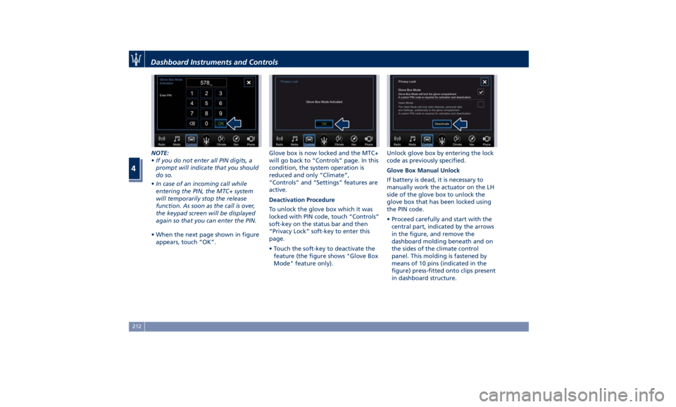
• When the next page shown in figure
appears, touch “OK”. Glove box is now locked and the MTC+
will go back to “Controls” page. In this
condition, the system operation is
reduced and only “Climate”,
“Controls” and “Settings” features are
active.
Deactivation Procedure
To unlock the glove box which it was
locked with PIN code, touch “Controls”
soft-key on the status bar and then
“Privacy Lock” soft-key to enter this
page.
• Touch the soft-key to deactivate the
feature (the figure shows "Glove Box
Mode" feature only). Unlock glove box by entering the lock
code as previously specified.
Glove Box Manual Unlock
If battery is dead, it is necessary to
manually work the actuator on the LH
side of the glove box to unlock the
glove box that has been locked using
the PIN code.
• Proceed carefully and start with the
central part, indicated by the arrows
in the figure, and remove the
dashboard molding beneath and on
the sides of the climate control
panel. This molding is fastened by
means of 10 pins (indicated in the
figure) press-fitted onto clips present
in dashboard structure.Dashboard Instruments and Controls
4
212
Page 233 of 436
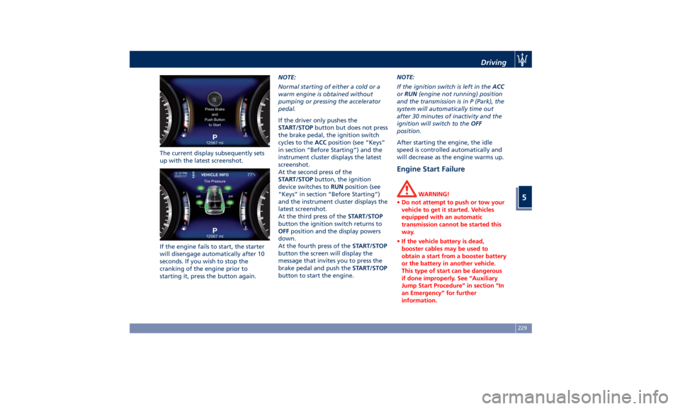
The current display subsequently sets
up with the latest screenshot.
If the engine fails to start, the starter
will disengage automatically after 10
seconds. If you wish to stop the
cranking of the engine prior to
starting it, press the button again. NOTE:
Normal starting of either a cold or a
warm engine is obtained without
pumping or pressing the accelerator
pedal.
If the driver only pushes the
START/STOP button but does not press
the brake pedal, the ignition switch
cycles to the ACC position (see “Keys”
in section “Before Starting”) and the
instrument cluster displays the latest
screenshot.
At the second press of the
START/STOP button, the ignition
device switches to RUN position (see
“Keys” in section “Before Starting”)
and the instrument cluster displays the
latest screenshot.
At the third press of the START/STOP
button the ignition switch returns to
OFF position and the display powers
down.
At the fourth press of the START/STOP
button the screen will display the
message that invites you to press the
brake pedal and push the START/STOP
button to start the engine. NOTE:
If the ignition switch is left in the ACC
or RUN (engine not running) position
and the transmission is in P (Park), the
system will automatically time out
after 30 minutes of inactivity and the
ignition will switch to the OFF
position.
After starting the engine, the idle
speed is controlled automatically and
will decrease as the engine warms up.
Engine Start Failure WARNING!
• Do not attempt to push or tow your
vehicle to get it started. Vehicles
equipped with an automatic
transmission cannot be started this
way.
• If the vehicle battery is dead,
booster cables may be used to
obtain a start from a booster battery
or the battery in another vehicle.
This type of start can be dangerous
if done improperly. See “Auxiliary
Jump Start Procedure” in section “In
an Emergency” for further
information.Driving
5
229
Page 354 of 436
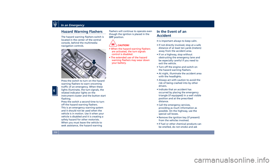
Hazard Warning Flashers The hazard warning flashers switch is
located in the center of the central
console, behind the multimedia
navigation controls.
Press the switch to turn on the hazard
warning flashers to warn oncoming
traffic of an emergency. When these
lights illuminate, the turn signals, the
related indicator lights on the
instrument cluster and the button start
flashing.
Press the switch a second time to turn
off the hazard warning flashers.
This is an emergency warning system
and it should not be used when the
vehicle is in motion. Use it when your
vehicle is disabled and it is creating a
safety hazard for other motorists.
When you must leave the vehicle to
seek assistance, the hazard warning flashers will continue to operate even
though the ignition is placed in the
OFF position.
CAUTION!
• When the hazard warning flashers
are activated, the turn signals
control is disabled.
• The extended use of the hazard
warning flashers may wear down
your battery.
In the Event of an
Accident It is important always to keep calm.
• If not directly involved, stop at a safe
distance of at least ten yards (meters)
away from the accident area.
• If on a highway, stop without
obstructing the emergency lane and
be especially careful if you need to
exit the vehicle.
• Turn off the engine and switch on
the hazard warning flashers.
• At night, illuminate the accident area
with the headlights.
• Always act with caution to avoid the
risk of being crashed into by other
drivers.
• Indicate that an accident has
occurred by placing the emergency
triangle (if equipped) in a well visible
position and at the prescribed
distance.
• Call the emergency services,
providing as much information as
possible. On the highway, use the
special call boxes.
• Remove the ignition key (if present)
from the vehicles involved.
• If fuel or other chemical products can
be smelled, do not smoke and askIn an Emergency
6
350
Page 387 of 436
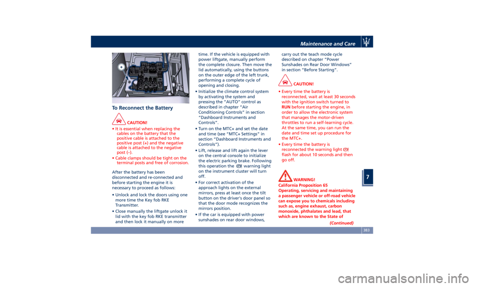
To Reconnect the Battery CAUTION!
• It is essential when replacing the
cables on the battery that the
positive cable is attached to the
positive post (+) and the negative
cable is attached to the negative
post (–).
• Cable clamps should be tight on the
terminal posts and free of corrosion.
After the battery has been
disconnected
and re-connected and
before starting the engine it is
necessary to proceed as follows:
• Unlock and lock the doors using one
more time the Key fob RKE
Transmitter.
• Close manually the liftgate unlock it
lid with the key fob RKE transmitter
and then lock it manually on more time. If the vehicle is equipped with
power liftgate, manually perform
the complete closure. Then move the
lid automatically, using the buttons
on the outer edge of the left trunk,
performing a complete cycle of
opening and closing.
• Initialize the climate control system
by activating the system and
pressing the “AUTO” control as
described in chapter “Air
Conditioning Controls” in section
“Dashboard Instruments and
Controls”.
• Turn on the MTC+ and set the date
and time (see “MTC+ Settings” in
section “Dashboard Instruments and
Controls”).
• Lift, release and lift again the lever
on the central console to initialize
the electric parking brake. Following
this operation the
warning light
on the instrument cluster will turn
off.
• For correct activation of the
approach lights on the external
mirrors, press at least once the tilt
button on the driver's door panel so
that the door mode recognizes the
mirrors position.
• If the car is equipped with power
sunshades on rear door windows, carry out the teach mode cycle
described on chapter “Power
Sunshades on Rear Door Windows”
in section “Before Starting”.
CAUTION!
• Every time the battery is
reconnected, wait at least 30 seconds
with the ignition switch turned to
RUN before starting the engine, in
order to allow the electronic system
that manages the motor-driven
throttles to run a self-learning cycle.
At the same time, you can run the
date and time set up procedure for
the MTC+.
• Every time the battery is
reconnected the warning light
flash for about 10 seconds and then
go off.
WARNING!
California Proposition 65
Operating, servicing and maintaining
a passenger vehicle or off-road vehicle
can expose you to chemicals including
such as, engine exhaust, carbon
monoxide, phthalates and lead, that
which are known to the State of
(Continued)Maintenance and Care
7
383
Page 430 of 436
Handholds and Cloth Hooks . . . .138
Hazard Warning Flashers ....... .350
Head Restraints ...............98
Highway Assist - HAS ......... .313
Hill Descend Control (HDC) ..... .277
HomeLink ................. .150
Security ................. .153
Troubleshooting Tips ........ .153
Using HomeLink ........... .153
Hood
Open and Close the Hood ......56
Hood Operation ..............56
HSA (Hill Start Assist) ......... .276
Identification Labels ............19
Illuminated Entry/Exit ...........30
Immobilizer (Sentry Key) .........26
Indicator Lights/Warning Lights
Air Bag Warning Light .........90
TFT Display: Menus and Settings .165
TFT Display: Warning/Indicator
Lights of Set Modes/Functions. . .178
Warning and Indicator Lights on
Analog Instrument ......... .161
Infotainment System .......... .185
Main Menu Bar on MTC+
Display ................. .187
Manual Controls and Devices . . .186
Personalized the Main Menu Bar.188
Instrument Cluster ........... .160
Interior Components ...........94
Interior Maintenance and Care. . . .400 Interiors Features ............ .133
iPad Holder ................ .139
iPod Connection ............. .136
Jump Start Procedure ......... .358
KeyFob ....................25
Key fob Battery Replacement ....35
Preventing Inadvertent Locking of
key fob RKE Transmitter Inside the
Vehicle ...................43
Replacement ...............27
Requiring and setting Additional
Key Fobs ..................34
Unlock the Vehicle with Key fob . .33
Keys .......................24
Lane Departure Warning (LDW) . . .301
Level Checks ............... .374
Brake Fluid Level Check ...... .375
Engine Coolant Level Check . . . .374
Engine Oil Level Check ....... .374
Fluid Level Check for Coolant
Transmission System ........ .379
Transmission Oil Check ....... .378
Washer/Headlight Fluid, adding .376
Liftgate
Automatic
Opening and Closing
Movement
of the Power Liftgate .51
Liftgate and Hood Ajar
Indicators ................ .180
Power Liftgate Emergency
Release ...................55 Power Liftgate Operation ......50
Unlatch the Liftgate ..........34
Lights .................... .113
Automatic Headlights ....... .115
Automatic Headlights Leveling . .126
Automatic High Beam ....... .120
Bi-Xenon Headlight ......... .117
Bulb Replacement .......... .393
Cargo Lamps ............. .127
Dome Lights .............. .126
DRL, Daytime Running Lights . . .116
Fog Lights ............... .123
Headlight Time Delay ....... .115
Headlight with AFS ......... .117
High Beam and Flashing ..... .124
Interior Lights ............. .125
Light Switch .............. .113
Multifunction Lever ......... .124
SmartBeam System ......... .116
Turn Signals .............. .124
Loading the Vehicle
Loading with Rear Seatbacks
Down .................. .141
Vehicle Load Carrying Capacity . .139
Main- and Submenu .......... .166
Maintenance ..................5
A/C System Maintenance ..... .395
Air Bag System Maintenance ....72
Bodywork Maintenance and
Care ................... .397
Emissions Inspection and
Maintenance Programs ...... .369Index
9 426