2019 MASERATI LEVANTE height
[x] Cancel search: heightPage 80 of 436
Here are some tips on getting
the most out of your child
restraint • Before buying any restraint system,
make sure that it has a label
certifying that it meets all applicable
Safety Standards. Maserati also
recommends that you make sure that
you can install the child restraint in
the vehicle where you will use it
before you buy it.
• The restraint system must be
appropriate for your child’s weight
and height.
• Check the label on the restraint
system for weight and height limits.
• Carefully follow the instructions that
come with the restraint system.
• If installed improperly, it may not
work when needed.
• Fit the child into the seat according
to the child restraint manufacturer’s
directions.
WARNING!
When your child restraint system is
not in use, secure it in the vehicle with
the seat belt or remove it from the
vehicle. Do not leave it loose in the
vehicle. In a sudden stop or accident, it could strike the occupants or
seatbacks and cause serious personal
injury.
Installing Child Restraint
Systems using the Vehicle Seat
Belt equipped with ALR Child restraint systems are designed to
be secured in vehicle seats by lap belts
or the lap belt portion of a
lap/shoulder belt.
All the passenger seat belts are
equipped with an Automatic Locking
Retractor (ALR) to secure child
protection through a Child Restraint
System (CRS). These types of seat belts
are designed to keep the lap portion
of the seat belt tight around the child
restraint seat avoiding to use a locking
clip.
The ALR will make a ratcheting noise if
the entire belt is pulled out of the
retractor in order to enable the belt to
retract subsequently. For additional
information on ALR, see “Using Seat
Belt in Automatic Locking Retractor
(ALR) Mode” in “Occupants Restraint
Systems” in this section.
To install a Child Restraint System with
ALR, pull enough of the belt out of the
retractor leading it through the belt
path of the protection device. Slide the latch into the buckle until it clicks,
then remove the entire safety belt
from the retractor in order to
rewound. While rewinding a click will
indicate the safety belt is now in
Automatic Locking mode.
Exert then a traction on the exceeded
lap section of the belt in order to
tighten it around the child restraint
seat. All seat belts will loosen over
time, it is therefore necessary to check
them periodically and set them
properly.
Lower Anchors and Tether for
Children (LATCH) Your vehicle's rear outboard seats are
all equipped with the child restraint
anchorage system called LATCH.
The LATCH system allows the child
restraint systems to be fixed without
using the vehicle's seat belts, instead
fixing the child restraint system to the
vehicle structure, using lower
anchorages A and upper tether strap
B .Before Starting
2
76
Page 99 of 436

1 Adjustable side air outlets.
2 Engine START/STOP button.
3 Light switch.
4 Anti-theft system indicator.
5 Steering wheel controls.
6 Instrument cluster.
7 Right shift paddle +.
8 Left shift paddle –.
9 Multifunction lever (windshield
wipers, headlight washer and
headlight selection, turn
signals).
10 Adjustable central air outlets.
11 Analog clock.
12 MTC+ display.
13 Climate controls.
14 Dashboard glove box handle.
15 Dashboard glove box with two
USB ports for charging of
connected source.
16 Steering wheel adjustment
control. Central Console Components 1 Automatic transmission shift
lever.
2 Drive mode switches.
3 Electric Parking Brake lever.
4 Cover for compartment with
AUX, USB and SD memory card
port. 5 Cover for cupholder and
cigarette lighter/power socket
compartment.
6 Rotary selectors and buttons for
the multimedia navigation.
7 Hazard flashers switch.
8 Drive height selector.Understanding the Vehicle
3
95
Page 102 of 436
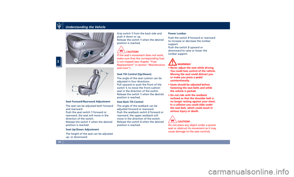
Seat Forward/Rearward Adjustment
The seat can be adjusted both forward
and rearward.
Push the seat switch 1 forward or
rearward, the seat will move in the
direction of the switch.
Release the switch 1 when the desired
position is reached.
Seat Up/Down Adjustment
The height of the seat can be adjusted
up- or downward. Grip switch 1 from the back side and
push it down or up.
Release the switch 1 when the desired
position is reached.
CAUTION!
If the seat's movement does not work,
make sure that the corresponding fuse
is not tripped (see chapter “Fuse
Replacement” in section “Maintenance
and Care”).
Seat Tilt Control (Up/Down)
The
angle of the seat cushion can be
adjusted in four directions.
Pull upward or push the front of the
switch 1 , to move the front cushion
seat in the direction of the switch.
Release the switch 1 when the desired
position is reached.
Seat Back Tilt Control
The angle of the seatback can be
adjusted forward or rearward.
Push the seatback switch 2 forward or
rearward, the upper seatback will
move in the direction of the switch.
Release the switch 2 when the desired
position is reached. Power Lumbar
Push the switch 3 forward or rearward
to increase or decrease the lumbar
support.
Push the switch 3 upward or
downward to raise or lower the
lumbar support.
WARNING!
• Never adjust the seat while driving.
You could lose control of the vehicle.
Moving the seat could distract you
or make you press a pedal
unintentionally.
• Seats should be adjusted before
fastening the seat belts and while
the vehicle is parked.
• Do not ride with the seatback
reclined so that the shoulder belt is
no longer resting against your chest.
In a collision you could slide under
the seat belt, which could result in
serious injury or death.
CAUTION!
Do not place any object under a power
seat or obstruct its movement as it may
cause damage to the seat controls.Understanding the Vehicle
3
98
Page 110 of 436
Front Head Restraints
Adjustment (for Comfort Seat
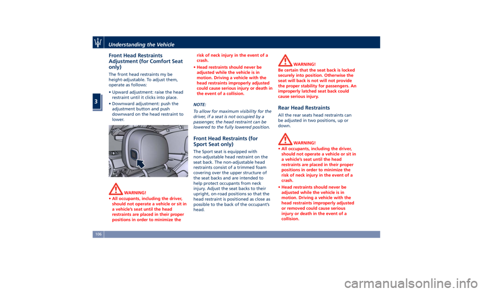
only) The front head restraints my be
height-adjustable. To adjust them,
operate as follows:
• Upward adjustment: raise the head
restraint until it clicks into place.
• Downward adjustment: push the
adjustment button and push
downward on the head restraint to
lower.
WARNING!
• All occupants, including the driver,
should not operate a vehicle or sit in
a vehicle’s seat until the head
restraints are placed in their proper
positions in order to minimize the risk of neck injury in the event of a
crash.
• Head restraints should never be
adjusted while the vehicle is in
motion. Driving a vehicle with the
head restraints improperly adjusted
could cause serious injury or death in
the event of a collision.
NOTE:
T
o allow for maximum visibility for the
driver, if a seat is not occupied by a
passenger, the head restraint can be
lowered to the fully lowered position.
Front Head Restraints (for
Sport Seat only) The Sport seat is equipped with
non-adjustable head restraint on the
seat back. The non-adjustable head
restraints consist of a trimmed foam
covering over the upper structure of
the seat backs and are intended to
help protect occupants from neck
injury. Adjust the seat backs to their
upright, on-road positions so that the
head restraint is positioned as close as
possible to the back of the occupant’s
head. WARNING!
Be certain that the seat back is locked
securely into position. Otherwise the
seat will back is not will not provide
the proper stability for passengers. An
improperly latched seat back could
cause serious injury.
Rear Head Restraints All the rear seats head restraints can
be adjusted in two positions, up or
down.
WARNING!
• All occupants, including the driver,
should not operate a vehicle or sit in
a vehicle’s seat until the head
restraints are placed in their proper
positions in order to minimize the
risk of neck injury in the event of a
crash.
• Head restraints should never be
adjusted while the vehicle is in
motion. Driving a vehicle with the
head restraints improperly adjusted
or removed could cause serious
injury or death in the event of a
collision.Understanding the Vehicle
3
106
Page 112 of 436
• Tilt the seat back to the upright
position (see “CArgo Area” in this
section).
• Reposition the head restraint to the
appropriate height for the passenger.
WARNING!
• A loose head restraint thrown
forward in a collision or hard stop
could cause serious injury or death
to occupants of the vehicle. Always
securely stow removed head
restraints in a location outside the
occupant compartment.
• ALL the head restraints MUST be
reinstalled in the vehicle to properly
protect the occupants. Follow the
re-installation instructions above
prior to operating the vehicle or
occupying a seat. Steering Wheel
Adjustment This feature allows you to tilt the
steering column upward or downward
or to lengthen or shorten it in order to
adjust the steering wheel to an
optimized position.
Power Adjustment The power tilt/telescoping steering
column/wheel switch is located on the
lower left side of the steering column.
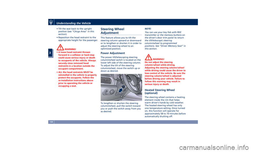
To adjust the tilt of the steering
column/wheel, move the switch up or
down as desired.
To lengthen or shorten the steering
column/wheel, pull the switch toward
you or push the switch away from you
as desired. NOTE:
You can use your key fob with RKE
transmitter or the memory buttons on
the driver's door trim panel to return
the tilt/telescopic steering
column/wheel to programmed
positions. See “Driver Memory Seat” in
this section.
WARNING!
Do not adjust the steering
column/wheel while driving.
Adjusting the steering column/wheel
while driving could cause the driver to
lose control of the vehicle. Be sure the
steering column/wheel is adjusted
before driving your vehicle. Failure to
follow this warning may result in
serious injury or death.
Heated Steering Wheel
(optional) The steering wheel contains a heating
element inside the rim that helps
warm driver’s hands by cold weather.
The heated steering wheel has only
one temperature setting. Once turned
on, this function will operate for
approximately 58 to 70 minutes before
automatically shutting off.Understanding the Vehicle
3
108
Page 170 of 436
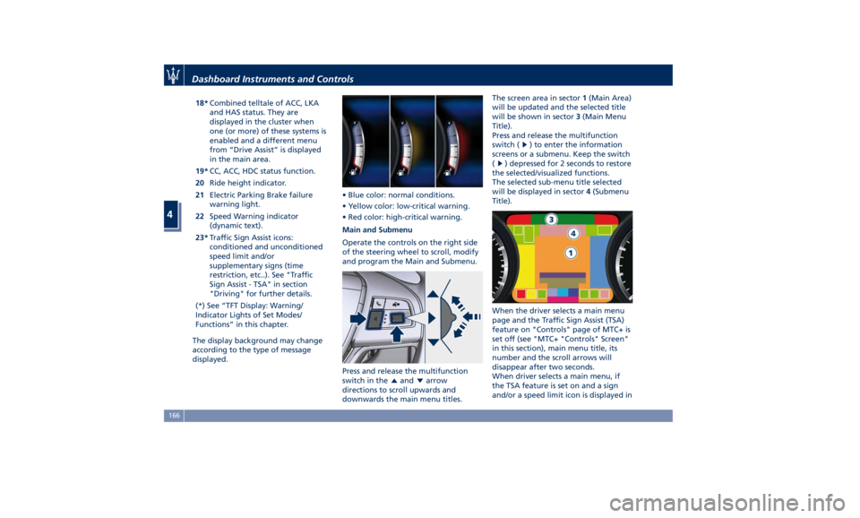
18* Combined telltale of ACC, LKA
and HAS status. They are
displayed in the cluster when
one (or more) of these systems is
enabled and a different menu
from “Drive Assist” is displayed
in the main area.
19* CC, ACC, HDC status function.
20 Ride height indicator.
21 Electric Parking Brake failure
warning light.
22 Speed Warning indicator
(dynamic text).
23* Traffic Sign Assist icons:
conditioned and unconditioned
speed limit and/or
supplementary signs (time
restriction, etc..). See "Traffic
Sign Assist - TSA" in section
"Driving" for further details.
(*) See “TFT Display: Warning/
Indicator Lights of Set Modes/
Functions” in this chapter.
The display background may change
according to the type of message
displayed. • Blue color: normal conditions.
• Yellow color: low-critical warning.
• Red color: high-critical warning.
Main and Submenu
Operate the controls on the right side
of the steering wheel to scroll, modify
and program the Main and Submenu.
Press and release the multifunction
switch in the
and arrow
directions to scroll upwards and
downwards the main menu titles. The screen area in sector 1 (Main Area)
will be updated and the selected title
will be shown in sector 3 (Main Menu
Title).
Press and release the multifunction
switch (
) to enter the information
screens or a submenu. Keep the switch
(
) depressed for 2 seconds to restore
the selected/visualized functions.
The selected sub-menu title selected
will be displayed in sector 4 (Submenu
Title).
When the driver selects a main menu
page and the Traffic Sign Assist (TSA)
feature on "Controls" page of MTC+ is
set off (see "MTC+ "Controls" Screen"
in this section), main menu title, its
number and the scroll arrows will
disappear after two seconds.
When driver selects a main menu, if
the TSA feature is set on and a sign
and/or a speed limit icon is displayed inDashboard Instruments and Controls
4
166
Page 171 of 436

sector 23, only the main menu number
and the scroll arrows remain displayed
in the sector 3 , left side.
Within a submenu, press and release
the switch in the
and arrow
directions to scroll the menu.
Press the
button to return to the
main menu from an item of interest or
from an information screen.
Main Menu & Submenu Content
Overview
1. MAIN MENU
• View speed in mph or km/h
2. VEHICLE INFO
• Tire Pressure
• Transmission Temperature
• Oil Temperature
• Oil Pressure
• Battery Voltage
• Maintenance 3. DRIVE MODE
• Drive Mode - Ride Height - Torque
Distribution - Powertrain status - ESC
status - Suspension stiffness status
4. Driver Assist (if equipped)
• Shows the status of any active driver
assist systems: CC, ACC, LKA and
HAS. Graphics in the main area of
TFT display only refer to ACC, LKA
and HAS systems
• LKA (LaneSense) status
5. FUEL ECONOMY
• Average, Range, Current gage
6. TRIP
• Trip A: Average, Avg. speed, Elapsed
time, Distance
• Trip B: Average, Avg. speed, Elapsed
time, Distance
7. START&STOP
• Messages relating to the Start&Stop
function
8. AUDIO
• Information concerning audio status
according to current media source,
track and station.
• Information on phone incoming call.
9. STORED MESSAGES
10. VEHICLE SETTINGS • Speed Warning: enables, disables or
sets the speed limit represented in
the dynamic icon on the TFT display
• Auto apply Off/On of the Electric
Parking Brake
• Interior Lighting
– Backlighting
– Ambient Lighting
• SCREEN SETUP
– Upper Left
– Upper Right
– Main Menu: Line 1
– Main Menu: Line 2
– Main Menu: Line 3
– MPH km/h Display On/Off
– Main Menu Navigation
– Outline Coloring
– Key-On Display
– Key-Off Display
– Defaults
Messages on Main Display Area
The main display area also displays
"pop up" messages. These pop up
messages fall into several categories:
• Five-Second Stored Messages
When the appropriate conditions
occur, this type of message appears
on the main display area for five
seconds and then returns to the
previous screen. Most of the
messages of this type are thenDashboard Instruments and Controls
4
167
Page 187 of 436
that a system fault requiring servicing
at an Authorized Maserati Dealer .Itis
nevertheless possible to drive the
vehicle without using this function
(for further details, refer to “Forward
Collision Warning - FCW” in section
“Driving”).
General Fault for Driving with a Trailer
(NOT for TROFEO version)
The warning light and the
relevant message are
displayed to indicate a fault or
failure of the connection
between vehicle and trailer. In these
cases please contact an Authorized
Maserati Dealer as soon as possible,
and avoid using the vehicle with a
trailer.
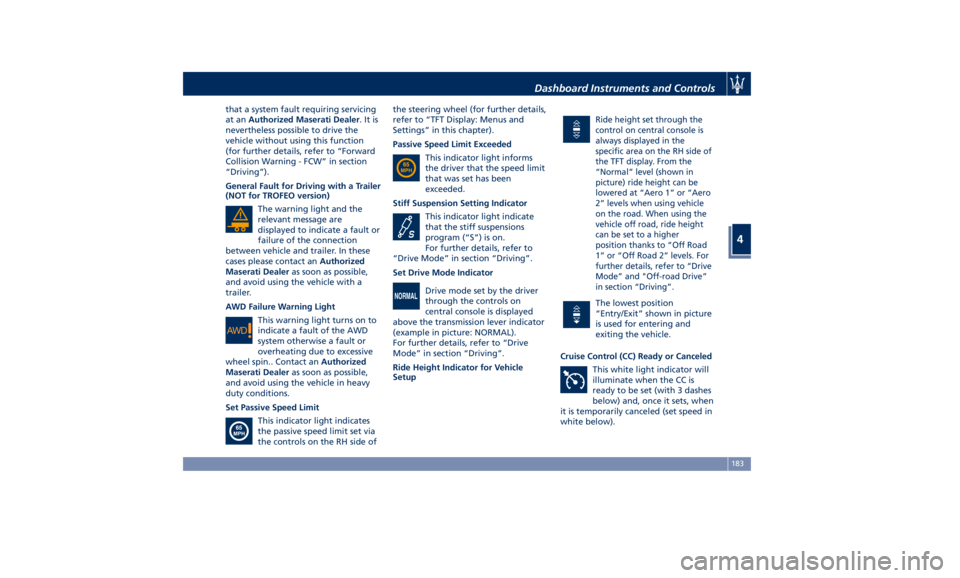
AWD Failure Warning Light
This warning light turns on to
indicate a fault of the AWD
system otherwise a fault or
overheating due to excessive
wheel spin.. Contact an Authorized
Maserati Dealer as soon as possible,
and avoid using the vehicle in heavy
duty conditions.
Set Passive Speed Limit
This indicator light indicates
the passive speed limit set via
the controls on the RH side of the steering wheel (for further details,
refer to “TFT Display: Menus and
Settings” in this chapter).
Passive Speed Limit Exceeded
This indicator light informs
the driver that the speed limit
that was set has been
exceeded.
Stiff Suspension Setting Indicator
This indicator light indicate
that the stiff suspensions
program (“S”) is on.
For further details, refer to
“Drive Mode” in section “Driving”.
Set Drive Mode Indicator
Drive mode set by the driver
through the controls on
central console is displayed
above the transmission lever indicator
(example in picture: NORMAL).
For further details, refer to “Drive
Mode” in section “Driving”.
Ride Height Indicator for Vehicle
Setup Ride height set through the
control on central console is
always displayed in the
specific area on the RH side of
the TFT display. From the
“Normal” level (shown in
picture) ride height can be
lowered at “Aero 1” or “Aero
2” levels when using vehicle
on the road. When using the
vehicle off road, ride height
can be set to a higher
position thanks to “Off Road
1” or “Off Road 2” levels. For
further details, refer to “Drive
Mode” and "Off-road Drive”
in section “Driving”.
The lowest position
“Entry/Exit” shown in picture
is used for entering and
exiting the vehicle.
Cruise Control (CC) Ready or Canceled
This white light indicator will
illuminate when the CC is
ready to be set (with 3 dashes
below) and, once it sets, when
it is temporarily canceled (set speed in
white below).Dashboard Instruments and Controls
4
183