2019 MASERATI GRANTURISMO CONVERTIBLE TPMS
[x] Cancel search: TPMSPage 11 of 296
Abbreviations Some descriptions and terms with
particular meanings are found in this
manual in abbreviated form.
A/C Air-Conditioning System.
ABS Anti-Lock Braking System.
ALC Adaptive Light Control.
ALR Automatic Locking Retractor.
ASR Anti-Slip Regulation.
BOS Brake Override System.
CAN Controller Area Network.
CC Cruise Control.
CRS Child Restraint System.
DRL Daytime Running Lights.
EBD Electronic Brake-force
Distribution.
ECU Electronic Control Unit.
EDR Event Data Recorder.
EPB Electric Parking Brake.
ESC Electronic Stability Control.
ETD Emergency Tensioning
Device.
FTP Flash To Pass.
HBA Hydraulic Brake Assistance.
ICE Increase Control and
Efficiency. LATCH Lower Anchors and Tether
for CHildren.
MIL Malfunction Indicator Light.
MTC+ Maserati Touch Control Plus.
OBD On Board Diagnostics.
ORC Occupant Restraint
Controller.
RHD Right-Hand Drive.
SBR Seat Belt Reminder.
TFT Thin Film Transistor.
TPMS Tire Pressure Monitoring
System.
VIN Vehicle Identification
Number. Updating Constant improvements are being
performed to maintain this vehicle's
high level of quality. Therefore, there
may be differences between this
manual and your vehicle.
Maserati reserves the right to carry
out design and functional changes
and to provide updates or
improvements.
This Owner's Manual illustrates and
describes all versions of the current
vehicle model. Therefore, some of the
equipment and accessories in this
publication may not appear on your
vehicle; please only consider the
information related to your vehicle.
All specifications and illustrations
contained in this manual are as of the
Manual publishing date.
NOTE:
The updated version of the on-board
documentation can be consulted by
accessing the section “SERVICES” on
the website www.maserati.com or by
using the specific apps developed for
the more common Tablet and
Smartphone. Introduction
1
7
Page 125 of 296
Left Turn Signal Indicator Light
The indicator lights up when
the left turn signals or the
hazard flashers are turned on.
The indicator light will flash at
the same frequency of the turn signals
and is controlled by the left
multifunction lever.
If the vehicle electronics sense that the
vehicle drives for more than 1 mile
(1.6 km) with either turn signal on, a
continuous sound will alert the driver
to turn the signal off.
If the indicator flashes at a rapid rate,
check for a defective exterior light
bulb.
Rear Fog Light Indicator
This indicator lights up when
the rear fog lights are
switched on.
Tire Pressure Monitoring Light (*)
This indicator light is
connected to the Tire Pressure
Monitoring System (TPMS).
Under normal conditions, the
warning light should illuminate when
the key in the ignition switch is in
MAR (ON) position and should go off
as soon as the engine is started.
If the warning light remains lit or
illuminates while driving, the pressure of one or more tires is too low: the
related message will be displayed.
If the warning light flashes prior to
remain on, it indicates that the system
is temporarily unavailable.
This warning light illuminates even
when you calibrate the TPMS and
remains lit until the system is
calibrated.
Please refer to “Tire Pressure
Monitoring System (TPMS)” in section
“Driving” for further information.
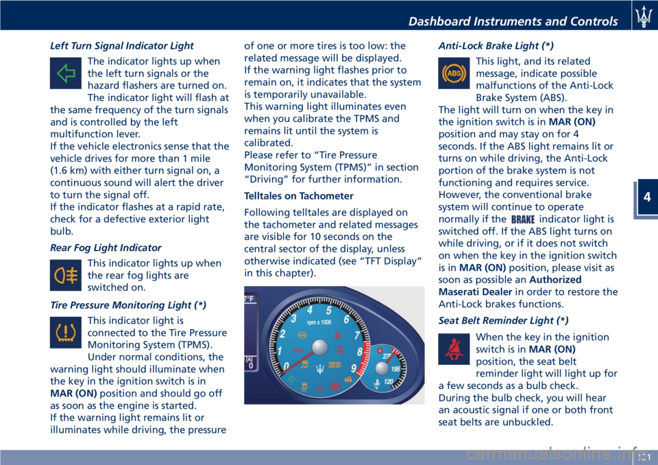
Telltales on Tachometer
Following telltales are displayed on
the tachometer and related messages
are visible for 10 seconds on the
central sector of the display, unless
otherwise indicated (see “TFT Display”
in this chapter). Anti-Lock Brake Light (*)
This light, and its related
message, indicate possible
malfunctions of the Anti-Lock
Brake System (ABS).
The light will turn on when the key in
the ignition switch is in MAR (ON)
position and may stay on for 4
seconds. If the ABS light remains lit or
turns on while driving, the Anti-Lock
portion of the brake system is not
functioning and requires service.
However, the conventional brake
system will continue to operate
normally if the
indicator light is
switched off. If the ABS light turns on
while driving, or if it does not switch
on when the key in the ignition switch
is in MAR (ON) position, please visit as
soon as possible an Authorized
Maserati Dealer in order to restore the
Anti-Lock brakes functions.
Seat Belt Reminder Light (*)
When the key in the ignition
switch is in MAR (ON)
position, the seat belt
reminder light will light up for
a few seconds as a bulb check.
During the bulb check, you will hear
an acoustic signal if one or both front
seat belts are unbuckled.Dashboard Instruments and Controls
4
121
Page 128 of 296
TFT Display: Menus and
Settings The TFT display performs the following
functions:
• provides general information while
driving;
• signals failures and warnings.
The user can interact with the system
by setting the parameters for the
information that can be recalled.
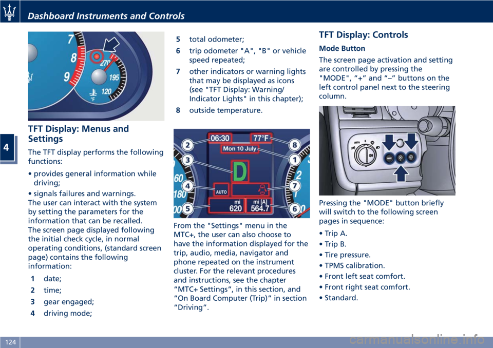
The screen page displayed following
the initial check cycle, in normal
operating conditions, (standard screen
page) contains the following
information:
1 date;
2 time;
3 gear engaged;
4 driving mode; 5 total odometer;
6 trip odometer "A", "B" or vehicle
speed repeated;
7 other indicators or warning lights
that may be displayed as icons
(see "TFT Display: Warning/
Indicator Lights" in this chapter);
8 outside temperature.
From the "Settings" menu in the
MTC+, the user can also choose to
have the information displayed for the
trip, audio, media, navigator and
phone repeated on the instrument
cluster. For the relevant procedures
and instructions, see the chapter
“MTC+ Settings”, in this section, and
“On Board Computer (Trip)” in section
“Driving”. TFT Display: Controls Mode Button
The screen page activation and setting
are controlled by pressing the
"MODE", “+” and “–” buttons on the
left control panel next to the steering
column.
Pressing the "MODE" button briefly
will switch to the following screen
pages in sequence:
• Trip A.
• Trip B.
• Tire pressure.
• TPMS calibration.
• Front left seat comfort.
• Front right seat comfort.
• Standard.Dashboard Instruments and Controls
4
124
Page 129 of 296
“+“ and “–” Buttons
By means of the “+ “ and “–” buttons,
the user can adjust the instrument
cluster brightness.
When a screen page is viewed, these
buttons can be used to select the
available options (see paragraph "TFT
Display: Screen Pages" in this chapter).
TFT Display: Screen Pages Trip Screen Page
The Trip screen page is recalled by
pressing the “MODE” button. Each
Trip screen page “A” or “B” is timed,
i.e. it is displayed for a maximum of 10
seconds, after which the screen page
previously active is displayed once
again.
Before the 10 second timing has
elapsed, pressing the “MODE” button
briefly (less than 2 seconds) will reset
the trip information relating to the
flashing odometer “A” or “B”.
When the “Trip A” or “Trip B” feature
is active, the following information is
viewed on the display:
• traveled distance (shown in the
lower right area);
• average fuel consumption (Avg.
cons.)
• average traveling speed (Avg.
speed); • trip time;
• fuel range (Range);
The unit for this data can be adjusted
by the user from the MTC+ Settings
menu.
NOTE:
Trip and Service information can be
viewed by accessing the “Trip” menu
on the MTC+ screen (see “On Board
Computer Trip (Trip)” in section
“Driving”).
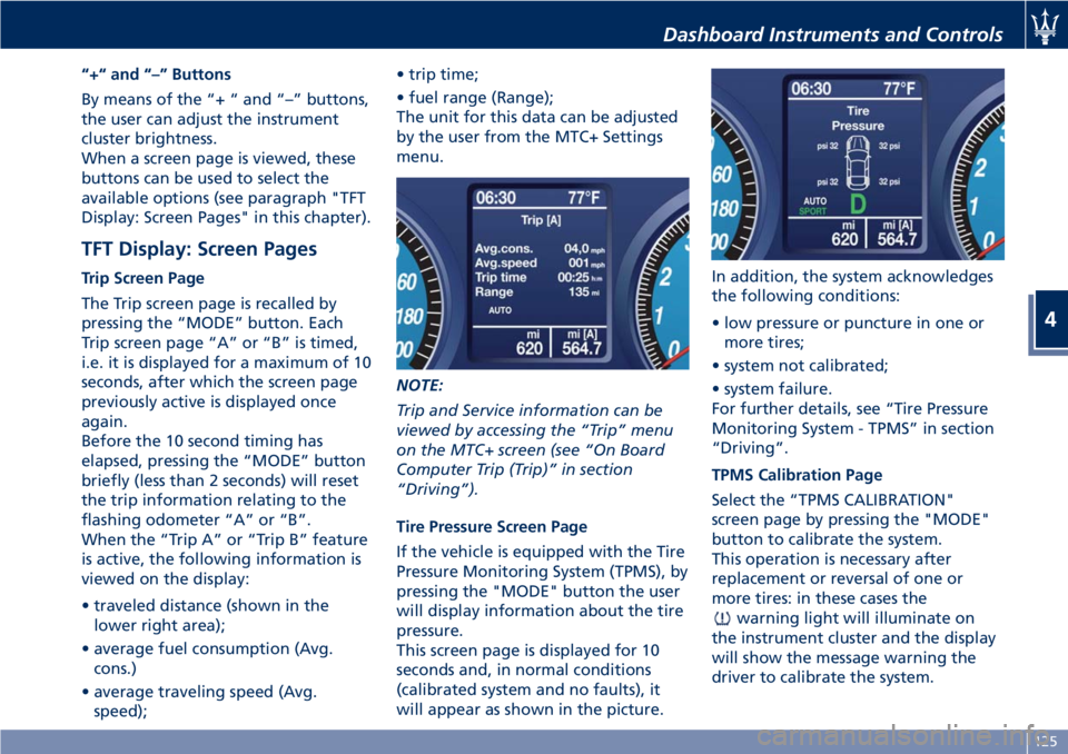
Tire Pressure Screen Page
If the vehicle is equipped with the Tire
Pressure Monitoring System (TPMS), by
pressing the "MODE" button the user
will display information about the tire
pressure.
This screen page is displayed for 10
seconds and, in normal conditions
(calibrated system and no faults), it
will appear as shown in the picture. In addition, the system acknowledges
the following conditions:
• low pressure or puncture in one or
more tires;
• system not calibrated;
• system failure.
For further details, see “Tire Pressure
Monitoring System - TPMS” in section
“Driving”.
TPMS Calibration Page
Select the “TPMS CALIBRATION"
screen page by pressing the "MODE"
button to calibrate the system.
This operation is necessary after
replacement or reversal of one or
more tires: in these cases the
warning light will illuminate on
the instrument cluster and the display
will show the message warning the
driver to calibrate the system.Dashboard Instruments and Controls
4
125
Page 130 of 296
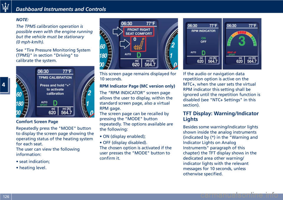
NOTE:
The TPMS calibration operation is
possible even with the engine running
but the vehicle must be stationary
(0 mph-km/h).
See "Tire Pressure Monitoring System
(TPMS)" in section "Driving" to
calibrate the system.
Comfort Screen Page
Repeatedly press the "MODE" button
to display the screen page showing the
operating status of the heating system
for each seat.
The user can view the following
information:
• seat indication;
• heating level. This screen page remains displayed for
10 seconds.
RPM Indicator Page (MC version only)
The “RPM INDICATOR” screen page
allows the user to display, within the
standard screen page, also a virtual
RPM gage.
The screen page can be recalled by
pressing the "MODE" button
repeatedly. The options available are
the following:
• ON (display enabled);
• OFF (display disabled).
The chosen option is activated if the
user presses the "MODE" button to
confirm it. If the audio or navigation data
repetition option is active on the
MTC+, when the user sets the virtual
RPM indicator this setting shall be
ignored until the repetition function is
disabled (see "NTC+ Settings" in this
section).
TFT Display: Warning/Indicator
Lights Besides some warning/indicator lights
shown inside the analog instruments
(indicated by (*) in the "Warning and
Indicator Lights on Analog
Instruments" paragraph of this
chapter) the TFT display shows in the
dedicated area other warning/
indicator lights with the relevant
messages for 10 seconds, unless
otherwise specified.Dashboard Instruments and Controls
4
126
Page 161 of 296
5 – Driving
Normal Starting of the Engine............................. 158
Automatic Transmission .................................. 160
Onboard Computer (Trip) ................................ 167
Drive Mode ........................................... 169
Parking Brake ......................................... 174
Parking .............................................. 176
Brake and Stability Control System ......................... 177
Using the Brakes ....................................... 181
Use of the Engine ...................................... 183
Cruise Control (CC) ...................................... 185
Tires - General Information ............................... 187
Tire Pressure Monitoring System - TPMS ...................... 194
Fuel Requirements ...................................... 199
Refueling ............................................. 202
Driving Conditions ...................................... 204
Pollution Control Devices ................................. 207
157
Page 194 of 296
All passenger car tires must conform to
Federal safety requirements in
addition to these grades.
Treadwear
The Treadwear grade is a comparative
rating, based on the wear rate of the
tire when tested under controlled
conditions on a specified government
test course. For example, a tire graded
150 would wear one and one-half
times as well on the government
course as a tire graded 100. The
relative performance of tires depends
upon the actual conditions of their
use, however, and may depart
significantly from the norm due to
variations in driving habits, service
practices, and differences in road
characteristics and climate.
Traction Grades
The Traction grades, from highest to
lowest, are AAA, A, B, and C. These
grades represent the tire's ability to
stop on wet pavement, as measured
under controlled conditions on
specified government test surfaces of
asphalt and concrete. A tire marked C
may have poor traction performance.
WARNING!
The traction grade assigned to this tire
is based on straight-ahead braking
traction tests, and does not include
acceleration, cornering, hydroplaning,
or peak traction characteristics.
Temperature Grades
The
temperature grades are A (the
highest), B, and C, representing the
tire's resistance to the generation of
heat and its ability to dissipate heat,
when tested under controlled
conditions on a specified indoor
laboratory test wheel. Sustained high
temperature can cause the material of
the tire to degenerate and reduce tire
life, and excessive temperature can
lead to sudden tire failure. The grade
C corresponds to a level of
performance, which all passenger car
tires must meet under the Federal
Motor Vehicle Safety Standard No.
109. Grades B and A represent higher
levels of performance on the
laboratory test wheel, than the
minimum required by law.
WARNING!
The temperature grade for this tire is
established for a tire that is properly
inflated and not overloaded. Excessive
speed, under-inflation, or excessive
loading, either separately or in
combination, can cause heat buildup
and possible tire failure.
Tire Pressure
Proper tire inflation pressure is
essential for safety and best
performance of your vehicle. The tire
pressure monitoring system “TPMS”
setup on the vehicle (see “Tire Pressure
Monitoring System” in this section)
may alert the driver about insufficient
tire pressure even though the driver is
responsible for regularly checking the
tire pressure.
Radial tires fitted on the vehicle may
look properly inflated even when they
actually are under inflated. Do not
make a visual judgment when
determining proper inflation.
Three primary driving aspects are
affected by improper tire pressure:
Safety
Driving
5
190
Page 195 of 296

WARNING!
• Improperly inflated tires can be
dangerous.
• Under-inflation increases tire flexing
and can result in tire overheating.
• Over-inflation reduces a tire's ability
to cushion shock. Objects on the
road and potholes can cause
damage that results in tire failure.
• Over-inflated or under-inflated tires
can affect vehicle handling and can
fail suddenly, resulting in loss of
vehicle control.
• Unequal tire pressures can cause
steering problems.
• Unequal tire pressures from one side
of the vehicle to the other can cause
the vehicle to drift to the right or
left.
• Always drive with each tire inflated
to the recommended cold tire
inflation pressure.
Economy
Improper
inflation pressures may
cause uneven wear patterns to
develop across the tire tread. These
abnormal wear patterns will reduce
tread life resulting in a need for
earlier tire replacement. Under- inflation also increases tire rolling
resistance resulting in higher fuel
consumption.
Ride comfort and vehicle stability
Proper tire inflation contributes to a
comfortable ride. Over-inflation
produces a jarring and uncomfortable
ride.
Tire Pressure Checkup
The proper cold tire inflation pressure
is indicated on the driver's side rear
door pillar and on the table “Tire
Inflation Pressure” in section
“Features and Specifications”.
Inflation pressure specified on the
table always refers to “cold tire
inflation pressure”. Cold tire inflation
pressure is defined as the tire pressure
after the vehicle has not been driven
for at least three hours, or driven less
than 1 mi (1,6 km) after a three hour
period.
Check tire pressures more often in
case of significant outside
temperature changes, as tire pressure
varies according to temperature
changes.
The pressure should be checked and if
necessary adjusted; tire wear and
overall conditions should also be
checked monthly. Tire pressures
change by approximately 1 PSI (0,07
bar) per 12°F (7°C) of air temperature
change. Keep this in mind when
checking tire pressure inside a garage,
especially in winter.
Example: If garage temperature = 68°F
(20°C) and the outside temperature =
32°F (0°C) then the cold tire inflation
pressure should be increased by 3 PSI
(0,21 bar) for every 12°F (7°C) for this
outside temperature condition.
Tire pressure may increase from 2 to 6
PSI (0,13 to 0,4 bar) during operation.
DO NOT reduce this normal pressure
build-up or your tire pressure will be
too low. After inspecting or adjusting
the tire pressure, always reinstall the
valve stem cap. This will prevent
moisture and dirt from entering the
valve stem, which could damage the
valve stem and the TPMS sensor
connected to it.
Tread Wear Indicators
Tread wear indicators are in the
original equipment tires to help you
determine when your tires should be
replaced.
These indicators are molded into the
bottom of the tread grooves.
When the tread is worn to one of the
tread wear indicators, the tire should
be replaced.
Driving
5
191