2019 LINCOLN MKZ jump cable
[x] Cancel search: jump cablePage 177 of 595

•An open or pinched sensor hose.
•Incorrect engine oil level.
•Incorrect fuel for climatic conditions.
•Incorrect engine oil viscosity for climacticconditions.
Note:Some vehicles have a lifetime fuel filterthat is integrated with the fuel tank. Regularmaintenance or replacement is not needed.
Note:If these checks do not help you correctthe concern, have your vehicle checked assoon as possible.
Noise Emissions Warranty, ProhibitedTampering Acts and Maintenance
On January 1, 1978, Federal regulationbecame effective governing the noiseemission on trucks over 10,000 lb (4,536 kg)Gross Vehicle Weight Rating (GVWR). Thepreceding statements concerning prohibitedtampering acts and maintenance, and thenoise warranty found in the Warranty Guide,are applicable to complete chassis cabs over10,000 lb (4,536 kg) GVWR.
CATALYTIC CONVERTER
WARNING: Do not park, idle or driveyour vehicle on dry grass or other dry groundcover. The emission system heats up theengine compartment and exhaust system,creating the risk of fire.
WARNING: The normal operatingtemperature of the exhaust system is veryhigh. Never work around or attempt to repairany part of the exhaust system until it hascooled. Use special care when workingaround the catalytic converter. The catalyticconverter heats up to a very hightemperature after only a short period ofengine operation and stays hot after theengine is switched off.
WARNING: Exhaust leaks may resultin entry of harmful and potentially lethalfumes into the passenger compartment. Ifyou smell exhaust fumes inside your vehicle,have your vehicle inspected immediately. Donot drive if you smell exhaust fumes.
Your vehicle has various emission controlcomponents and a catalytic converter thatenables it to comply with applicable exhaustemission standards.
To make sure that the catalytic converter andother emission control components continueto work properly:
•Do not crank the engine for more than10 seconds at a time.
•Do not run the engine with a spark pluglead disconnected.
•Do not push-start or tow-start yourvehicle. Use booster cables. See JumpStarting the Vehicle (page 264).
•Use only the specified fuel listed.
•Do not switch the ignition off when yourvehicle is moving.
•Avoid running out of fuel.
•Have the items listed in scheduledmaintenance information performedaccording to the specified schedule.
Note:Resulting component damage maynot be covered by the vehicle Warranty.
174
MKZ (CC9) Canada/United States of America, enUSA, Edition date: 201805, First-Printing
Engine Emission Control
Page 184 of 595

WARNING: If the parking brake is fullyreleased, but the brake warning lampremains illuminated, the brakes may not beworking properly. Have your vehicle checkedas soon as possible.
Note:See your authorized dealer as soonas possible if this procedure is used.
Note:For some markets this feature isdisabled.
Note:This feature will only function if your12-volt battery has power. If vehicle batteryvoltage is not sufficient, an external 12-voltpower source (for example, jumper cables,battery charger or jump pack) may berequired to function the interlock overrideswitch.
Use the brake-shift interlock override tomove your transmission from the parkposition in the event of an electricalmalfunction. If your vehicle has a deadbattery, an external power source will berequired.
1. Apply the parking brake and turn yourignition off before performing thisprocedure.
2. Locate your brake-shift interlock accessslot. The slot is located near the centerconsole. The access slot does not havea label.
Note:Make sure that you correctly identifythe access hole as not to damage the mediahub.
3. Using a tool, press and hold the brakeshift interlock switch. The shift buttonson the instrument panel will flash whenyour vehicle is in override mode.
4. With the override switch still held, pressthe neutral button (N) to shift from park.
5. Release the override button.
6.Your vehicle will remain in Stay in Neutralmode for wrecker towing purposes orcan be shifted to the desired gear anddriven (if possible).
7. Release the parking brake.
181
MKZ (CC9) Canada/United States of America, enUSA, Edition date: 201805, First-Printing
TransmissionE240975
Page 267 of 595

1. Press START/STOP to switch off yourvehicle.
2.Press the brake pedal and START/STOPto switch on your vehicle.
3. Remove your foot from the brake pedaland press START/STOP to switch offyour vehicle.
4. You can attempt to start the vehicle bypressing the brake pedal andSTART/STOP, or press START/STOPwithout pressing the brake pedal.
JUMP STARTING THE VEHICLE
WARNING: Batteries normally produceexplosive gases which can cause personalinjury. Therefore, do not allow flames, sparksor lighted substances to come near thebattery. When working near the battery,always shield your face and protect youreyes. Always provide correct ventilation.
WARNING: Keep batteries out of reachof children. Batteries contain sulfuric acid.Avoid contact with skin, eyes or clothing.Shield your eyes when working near thebattery to protect against possible splashingof acid solution. In case of acid contact withskin or eyes, flush immediately with waterfor a minimum of 15 minutes and get promptmedical attention. If acid is swallowed, call aphysician immediately.
WARNING: Use only adequately sizedcables with insulated clamps.
Preparing Your Vehicle
Do not attempt to push-start your automatictransmission vehicle.
Note:Attempting to push-start a vehicle withan automatic transmission may causetransmission damage.
Note:Use only a 12-volt supply to start yourvehicle.
Note:Do not disconnect the battery of thedisabled vehicle as this could damage thevehicle electrical system.
Park the booster vehicle close to the hoodof the disabled vehicle, making sure the twovehicles do not touch.
Connecting the Jumper Cables
WARNING: Do not connect the end ofthe second cable to the negative (-) terminalof the battery to be jumped. A spark maycause an explosion of the gases thatsurround the battery.
WARNING: Do not use fuel lines,engine valve covers, windshield wiper arms,the intake manifold, or hood latch as groundpoints.
Note:Do not attach the end of the positivecable to the studs or L-shaped eyelet locatedabove the positive (+) terminal of yourvehicle’s battery. High current may flowthrough and cause damage to the fuses.
264
MKZ (CC9) Canada/United States of America, enUSA, Edition date: 201805, First-Printing
Roadside Emergencies
Page 268 of 595

Note:To avoid reverse polarity connections,make sure that you correctly identify thepositive (+) and negative (-) terminals on boththe disabled and booster vehicles beforeconnecting the cables.
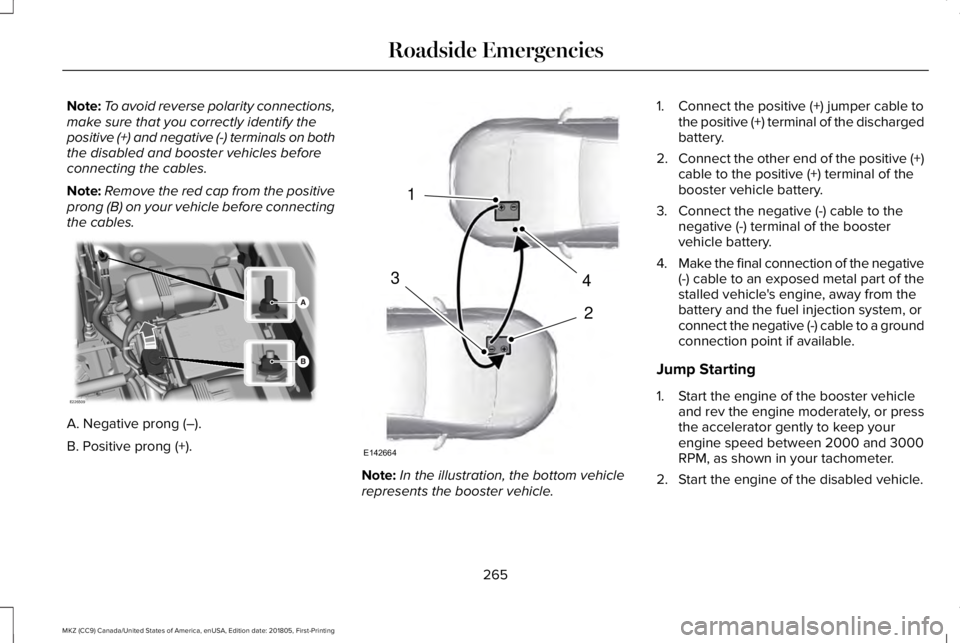
Note:Remove the red cap from the positiveprong (B) on your vehicle before connectingthe cables.
A. Negative prong (–).
B. Positive prong (+).
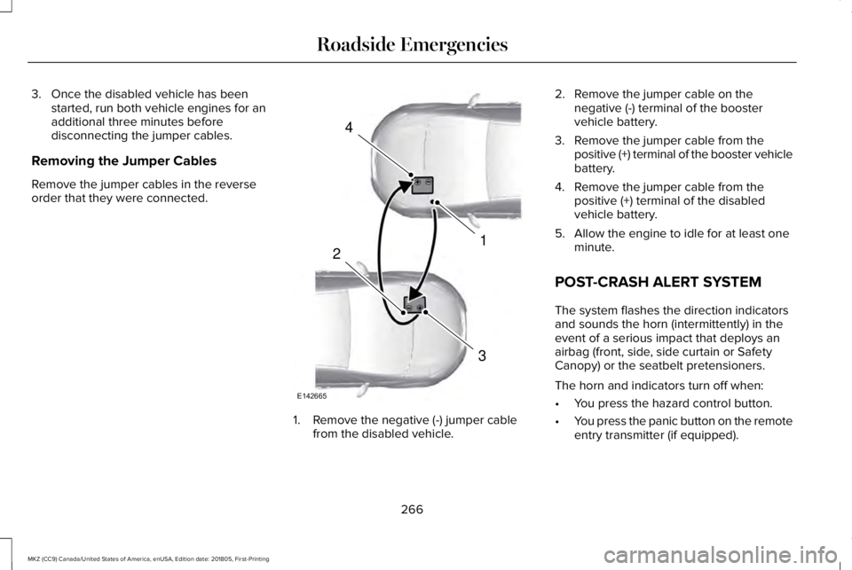
Note:In the illustration, the bottom vehiclerepresents the booster vehicle.
1. Connect the positive (+) jumper cable tothe positive (+) terminal of the dischargedbattery.
2.Connect the other end of the positive (+)cable to the positive (+) terminal of thebooster vehicle battery.
3. Connect the negative (-) cable to thenegative (-) terminal of the boostervehicle battery.
4.Make the final connection of the negative(-) cable to an exposed metal part of thestalled vehicle's engine, away from thebattery and the fuel injection system, orconnect the negative (-) cable to a groundconnection point if available.
Jump Starting
1. Start the engine of the booster vehicleand rev the engine moderately, or pressthe accelerator gently to keep yourengine speed between 2000 and 3000RPM, as shown in your tachometer.
2. Start the engine of the disabled vehicle.
265
MKZ (CC9) Canada/United States of America, enUSA, Edition date: 201805, First-Printing
Roadside EmergenciesE226509 4
2
1
3
E142664
Page 269 of 595

3. Once the disabled vehicle has beenstarted, run both vehicle engines for anadditional three minutes beforedisconnecting the jumper cables.
Removing the Jumper Cables
Remove the jumper cables in the reverseorder that they were connected.
1. Remove the negative (-) jumper cablefrom the disabled vehicle.
2. Remove the jumper cable on thenegative (-) terminal of the boostervehicle battery.
3. Remove the jumper cable from thepositive (+) terminal of the booster vehiclebattery.
4. Remove the jumper cable from thepositive (+) terminal of the disabledvehicle battery.
5. Allow the engine to idle for at least oneminute.
POST-CRASH ALERT SYSTEM
The system flashes the direction indicatorsand sounds the horn (intermittently) in theevent of a serious impact that deploys anairbag (front, side, side curtain or SafetyCanopy) or the seatbelt pretensioners.
The horn and indicators turn off when:
•You press the hazard control button.
•You press the panic button on the remoteentry transmitter (if equipped).
266
MKZ (CC9) Canada/United States of America, enUSA, Edition date: 201805, First-Printing
Roadside Emergencies4
1
3
2
E142665
Page 318 of 595

Because your vehicle’s engine iselectronically-controlled by a computer,some engine control settings are maintainedby power from the battery. Some enginecomputer settings, like the idle trim and fueltrim strategy, optimize the driveability andperformance of the engine. The clock andradio station presets are also maintained inmemory by power from the low-voltagebattery. These settings are erased when atechnician disconnects and connects thelow-voltage battery.
To restore the settings, do the following:
Note:Until you switch the ignition to the onposition, you will receive a message in yourinformation display stating that your vehicleis not in park.
1. Apply the parking brake.
2. Shift into park (P) or neutral (N).
3. Switch off all accessories.
4. Press the brake pedal and start yourvehicle.
5. Run the engine until it reaches normaloperating temperature. While the engineis warming up, complete the following:Reset the clock. See Audio Unit (page391). Reset the power windowsbounce-back feature. See PowerWindows (page 95). Reset the radiostation presets. See Audio Unit (page391).
6. Allow the engine to idle for at least oneminute.
7.Drive the vehicle at least 10 mi (16 km) tocompletely relearn the idle trim and fueltrim strategy.
Note:If you do not allow the engine torelearn the idle and fuel trim strategy, theidle quality of your vehicle may be adverselyaffected until the engine computereventually relearns the idle trim and fuel trimstrategy.
Note:Certain features may not operate ifthe battery monitor system is not reset witha scan tool following a jump start or batteryreplacement. Normal electrical accessoryoperation should resume after your vehicleis left undisturbed for 8 hours.
Make sure that you dispose of old batteriesin an environmentally friendly way. Seekadvice from your local authority aboutrecycling old batteries.
If storing your vehicle for more than 30 dayswithout recharging the battery, werecommend that you disconnect the batterycables to maintain battery charge for quickstarting.
CHECKING THE WIPER BLADES
Run the tip of your fingers over the edge ofthe blade to check for roughness.
Clean the wiper blades with washer fluid orwater applied with a soft sponge or cloth.
315
MKZ (CC9) Canada/United States of America, enUSA, Edition date: 201805, First-Printing
MaintenanceE142463
Page 590 of 595

J
Jump Starting the Vehicle..........................264Connecting the Jumper Cables.....................264Jump Starting......................................................265Preparing Your Vehicle.....................................264Removing the Jumper Cables........................266
K
Keyless Entry....................................................73SECURICODE™ KEYLESS ENTRYKEYPAD...............................................................73
Keyless Starting..............................................161Ignition Modes......................................................161
Keys and Remote Controls...........................57
L
Lane Keeping System.................................229Switching the System On and Off..................230
Lighting Control...............................................87Flashing the Headlamp High Beam.................88Headlamp High Beam.........................................88
Lighting..............................................................87General Information..............................................87
Lincoln Automotive Financial Services......12
Lincoln Protect...............................................501Lincoln Protect (CANADA ONLY)...................502Lincoln Protect Extended Service Plans (U.S.Only)...................................................................501
Load Carrying................................................248Load Limit.......................................................248Special Loading Instructions for Owners ofPick-up Trucks and Utility-typeVehicles............................................................252Vehicle Loading - with and without aTrailer................................................................248
Locking and Unlocking..................................67Activating Intelligent Access.............................68Autolock..................................................................70Battery Saver...........................................................71Illuminated Entry...................................................70Illuminated Exit......................................................70Locking and Unlocking the Doors with theKey Blade...........................................................69Luggage Compartment........................................71Power Door Locks................................................67Remote Control.....................................................67Smart Unlocks for Intelligent AccessKeys.....................................................................69
Lug NutsSee: Changing a Road Wheel.........................356
M
Maintenance..................................................297General Information...........................................297
Media Hub......................................................392Memory Function...........................................147Easy Entry and Exit Feature..............................148Linking a PreSet Position to your RemoteControl or Intelligent Access Key Fob.......148Saving a PreSet Position....................................147
Message CenterSee: Information Displays..................................110
MirrorsSee: Windows and Mirrors.................................95
Mobile Communications Equipment...........14Moonroof.........................................................100Opening and Closing.........................................102Type 1.......................................................................101Type 2.....................................................................101
Motorcraft Parts - 2.0L................................368Motorcraft Parts - 3.0L.................................370MyKey Troubleshooting................................65MyKey™..............................................................62Principle of Operation.........................................62
587
MKZ (CC9) Canada/United States of America, enUSA, Edition date: 201805, First-Printing
Index