2019 Lexus ES300h lane
[x] Cancel search: lanePage 183 of 456
1834-5. Using the driving support systems
4
Driving
• Width of traffic lane is approximately 9.8
ft. (3 m) or more.
• No system malfunctions are detected. ( P.184)
●Lane centering function
This function operates when all of the fol-
lowing conditions are met.
• LTA is turned on.
• Setting for “Steering Assist” and “Lane
Center” in of th e multi-information
display are set to “On”. ( P.73)
• This function recognizes white (yellow) lane lines or the position of a preceding
vehicle (except when the preceding vehi-
cle is small, such as a motorcycle).
• The dynamic radar cruise control with full-speed range is operating in vehicle-
to-vehicle distance control mode.
• Width of traffic lane is approximately 10 to 13 ft. (3 to 4 m).
• Turn signal lever is not operated.
• Vehicle is not being driven around a
sharp curve.
• No system malfunctions are detected.
( P.184)
• Vehicle does not acc elerate or deceler-
ate by a fixed amount or more.
• Steering wheel is not operated with a steering force level su itable for changing
lanes.
• ABS, VSC, TRAC and PCS are not oper- ating.
• TRAC or VSC is not turned off.
• Hands off steering wheel warning is not
displayed. ( P.183)
• The vehicle is being driven in the center of a lane.
• Steering assist function is not operating.
■Temporary cancelation of functions
When operation conditions are no longer
met, a function may be temporarily can-
celed. However, when the operation condi-
tions are met again, operation of the
function is automatically restored. ( P.182)
If the operation conditions ( P.182) are no
longer met while the lane centering func-
tion is operating, th e steering wheel may
vibrate and the buzzer may sound to indi-
cate that the function has been temporarily
canceled. However, if the “Steering wheel
vibration” customization setting is set to “On”, the system will notify the driver by
vibrating the steering wheel instead of
sounding the buzzer.
■Steering assist function/lane centering
function
●Depending on the vehicle speed, lane
departure situation, road conditions, etc.,
the driver may not feel the function is
operating or the function may not oper-
ate at all.
●The steering control of the function is
overridden by the driver’s steering wheel
operation.
●Do not attempt to test the operation of
the steering assist function.
■Lane departure alert function
●The warning buzzer may be difficult to
hear due to external noise, audio play-
back, etc. Also, it may be difficult to feel
steering wheel vibrations due to the road
conditions, etc.
●If the edge of the course* is not clear or
straight, the lane departure alert function
may not operate.
●Vehicles with Blind Spot Monitor: It may
not be possible for the system to deter-
mine if there is a danger of a collision with
a vehicle in an adjacent lane.
●Do not attempt to test the operation of
the lane departure alert function.
*: Boundary between asphalt and the side
of the road, such as grass, soil, or a curb
■Hands off steering wheel warning
In the following situations, a warning mes-
sage urging the driver to hold the steering
wheel and the symbol sh own in the illustra-
tion are displayed on the multi-information
display to warn the driver. The warning
stops when the system determines that the
driver holds the steering wheel. Always
keep your hands on the steering wheel
when using this system , regardless of warn-
ings.
Page 184 of 456

1844-5. Using the driving support systems
●When the system determines that the
driver is driving without holding the steer-
ing wheel while the system is operating
If the driver continue s to keep their hands
off of the steering wheel, the buzzer sounds,
the driver is warned and the function is tem-
porarily canceled. This warning also oper-
ates in the same way when the driver
continuously operates the steering wheel
only a small amount.
The buzzer also sounds even if the alert
type is set to “Steering wheel vibration”.
●When the system determines that the
vehicle may not turn and instead depart
from its lane while driving around a curve
Depending on the vehicle condition and
road conditions, the warning may not oper-
ate. Also, if the system determines that the
vehicle is driving around a curve, warnings
will occur earlier than during straight-lane
driving.
●When the system determines that the
driver is driving without holding the steer-
ing wheel while the st eering wheel assist
of the steering assist function is operat-
ing.
If the driver continue s to keep their hands
off of the steering wheel and the steering
wheel assist is operating, the buzzer sounds
and the driver is warned. Each time the
buzzer sounds, the continuing time of the
buzzer becomes longer.
The buzzer also sounds even if the alert
type is set to “Steering wheel vibration”.
■Vehicle sway warning function
When the system determines that the vehi- cle is swaying while the vehicle sway warn-
ing function is operating, a buzzer sounds
and a warning message urging the driver to
rest and the symbol sh
own in the illustration
are simultaneously di splayed on the multi-
information display.
Depending on the vehicle and road condi-
tions, the warning may not operate.
■Warning message
If the following warning message is dis-
played on the multi-in formation display and
the LTA indicator illuminates in orange, fol-
low the appropriate troubleshooting proce-
dure. Also, if a different warning message is
displayed, follow the instructions displayed
on the screen.
●“LTA Malfunction Visit Your Dealer”
The system may not be operating properly.
Have the vehicle inspected by your Lexus
dealer.
●“LTA Unavailable”
The system is temporarily canceled due to a
malfunction in a sensor other than the front
camera. Turn the LTA system off, wait for a
little while, and then turn the LTA system
back on.
●“LTA Unavailable at Current Speed”
The function cannot be used as the vehicle
speed exceeds the LTA operation range.
Drive slower.
■Customization
Function settings can be changed.
(Customizable features: P.412)
Page 186 of 456
1864-5. Using the driving support systems
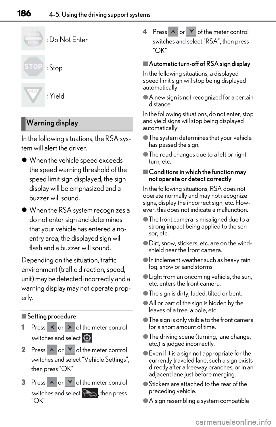
: Do Not Enter
: Stop
: Yield
In the following situations, the RSA sys-
tem will alert the driver.
When the vehicle speed exceeds
the speed warning threshold of the
speed limit sign displayed, the sign
display will be emphasized and a
buzzer will sound.
When the RSA system recognizes a
do not enter sign and determines
that your vehicle has entered a no-
entry area, the displayed sign will
flash and a buzzer will sound.
Depending on the situation, traffic
environment (traffic direction, speed,
unit) may be detected incorrectly and a
warning display may not operate prop-
erly.
■Setting procedure
1 Press or of the meter control
switches and select
2 Press or of the meter control
switches and select “Vehicle Settings”,
then press “OK”
3 Press or of the meter control
switches and select , then press
“OK” 4
Press or of the meter control
switches and select “RSA”, then press
“OK”
■Automatic turn-off of RSA sign display
In the following situations, a displayed
speed limit sign will stop being displayed
automatically:
●A new sign is not recognized for a certain
distance.
In the following situations, do not enter, stop
and yield signs will stop being displayed
automatically:
●The system determines that your vehicle
has passed the sign.
●The road changes due to a left or right
turn, etc.
■Conditions in which the function may
not operate or detect correctly
In the following situations, RSA does not
operate normally and may not recognize
signs, display the incorrect sign, etc. How-
ever, this does not indicate a malfunction.
●The front camera is misaligned due to a
strong impact being applied to the sen-
sor, etc.
●Dirt, snow, stickers, etc. are on the wind-
shield near the front camera.
●In inclement weather such as heavy rain,
fog, snow or sand storms
●Light from an oncoming vehicle, the sun,
etc. enters the front camera.
●The sign is dirty, faded, tilted or bent.
●All or part of the sign is hidden by the
leaves of a tree, a pole, etc.
●The sign is only visible to the front camera
for a short amount of time.
●The driving scene (turning, lane change,
etc.) is judged incorrectly.
●Even if it is a sign not appropriate for the
currently traveled lane, such a sign exists
directly after a freeway branches, or in an
adjacent lane just before merging.
●Stickers are attached to the rear of the
preceding vehicle.
●A sign resembling a system compatible
Warning display
Page 190 of 456
1904-5. Using the driving support systems
This mode employs a radar to detect the presence of vehicles up to approximately
328 ft. (100 m) ahead, determines the cu rrent vehicle-to-vehicle following dis-
tance, and operates to maintain a suitab le following distance from the vehicle
ahead. The desired vehicle-to-vehicle distance can also be set by operating the
vehicle-to-vehicle distance switch.
When driving on downhill slopes, the vehicl e-to-vehicle distance may become shorter.
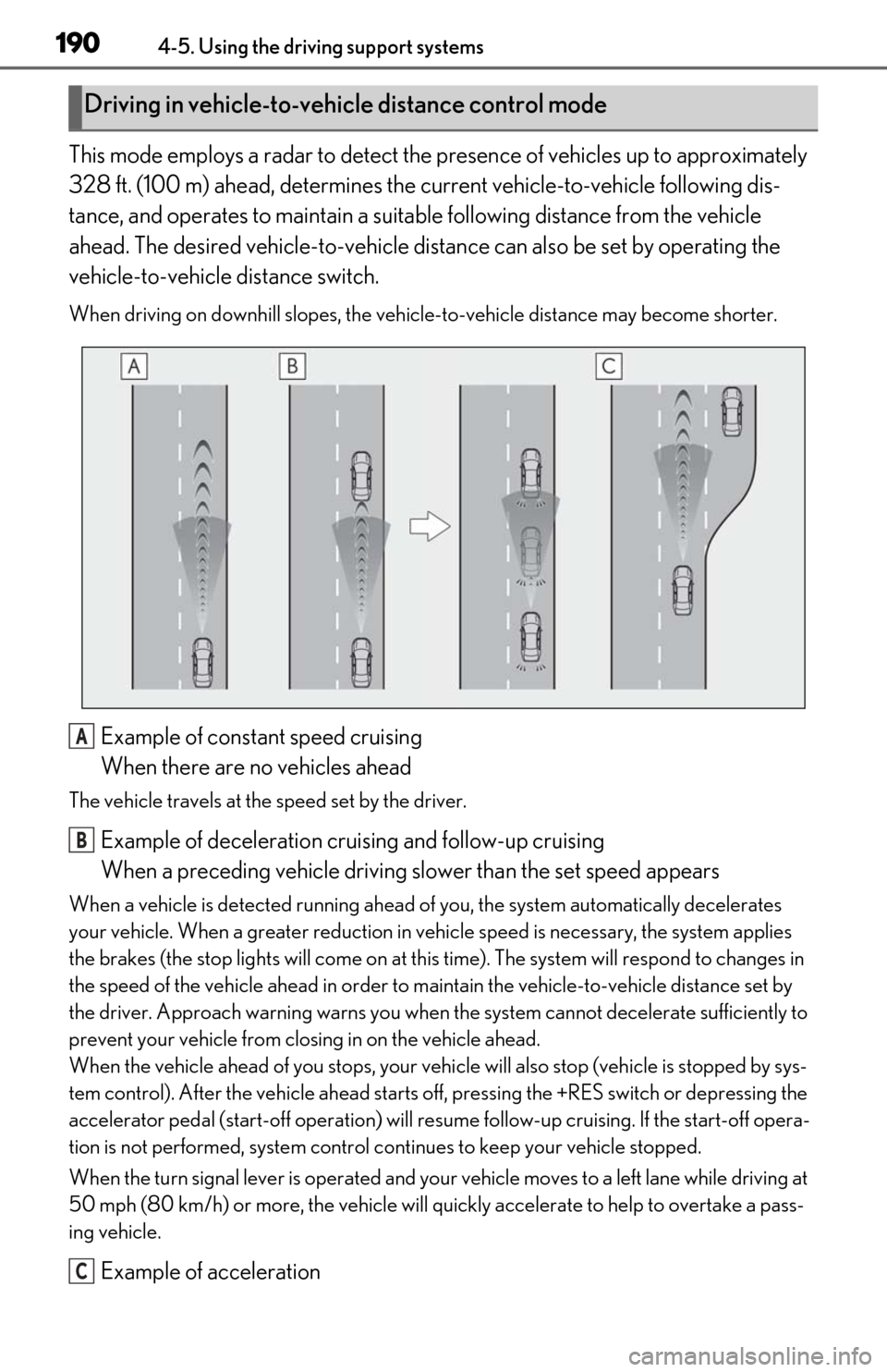
Example of constant speed cruising
When there are no vehicles ahead
The vehicle travels at the speed set by the driver.
Example of deceleration cruising and follow-up cruising
When a preceding vehicle driving slower than the set speed appears
When a vehicle is detected running ahead of you, the system automatically decelerates
your vehicle. When a greater reduction in vehicle speed is necessary, the system applies
the brakes (the stop lights will come on at this time). The sy stem will respond to changes in
the speed of the vehicle ahead in order to maintain the vehicle-to-vehicle distance set by
the driver. Approach warning warns you when th e system cannot decelerate sufficiently to
prevent your vehicle from closing in on the vehicle ahead.
When the vehicle ahead of you stops, your vehi cle will also stop (vehicle is stopped by sys-
tem control). After the vehicle ahead starts off, pressing the +RES switch or depressing the
accelerator pedal (start-off operation) will re sume follow-up cruising. If the start-off opera-
tion is not performed, system control continues to keep your vehicle stopped.
When the turn signal lever is operated and your vehicle moves to a left lane while driving at
50 mph (80 km/h) or more, the vehicle will quickly accelerate to help to overtake a pass-
ing vehicle.
Example of acceleration
Driving in vehicle-to-vehicle distance control mode
A
B
C
Page 196 of 456

1964-5. Using the driving support systems
●Vehicles traveling at low speeds
●Vehicles that are not moving in the same
lane
●Vehicles with small rear ends (trailers
with no load on board, etc.)
●Motorcycles traveling in the same lane
●When water or snow thrown up by the
surrounding vehicles hinders the detect-
ing of the sensor
●When your vehicle is pointing upwards
(caused by a heavy load in the luggage
compartment, etc.)
●Preceding vehicle has an extremely high
ground clearance
■Conditions under which the vehicle-to-
vehicle distance control mode may not
function correctly
In the case of the following conditions,
operate the brake pedal (or accelerator
pedal, depending on the situation) as nec-
essary.
As the sensor may not be able to correctly
detect vehicles ahead, the system may not operate properly.
●When the road curves or when the lanes
are narrow
●When steering wheel operation or your
position in the lane is unstable
●When the vehicle ahead of you deceler-
ates suddenly
●When driving on a road surrounded by a
structure, such as in a tunnel or on a
bridge
●While the vehicle speed is decreasing to
the set speed after the vehicle acceler-
ates by depressing the accelerator pedal
Page 197 of 456

1974-5. Using the driving support systems
4
Driving
*: If equipped
Meter control switches
Turn the Blind Spot Monitor on/off.
Outside rear view mirror indicators
When a vehicle is detected in a blind spot
of the outside rear view mirrors or
approaching rapidly from behind into a
blind spot, the outside rear view mirror
indicator on the detected side will illumi-
nate. If the turn signal lever is operated
toward the detected side, the outside rear
view mirror indicator will flash.
BSM indicator
When the Blind Spot Monitor is turned on,
the indicator comes on.
1Press or of the meter con-
trol switches, select .
2
Press or of the meter con-
trol switches, select “BSM”, and
then press “OK”.
■Outside rear view mirror indicator visi-
bility
In strong sunlight, the outside rear view mir-
ror indicator may be difficult to see.
■When “Blind Spot Monitor Unavailable”
is shown on the multi-information dis-
play
Ice, snow, mud, etc., may be attached to the
rear bumper around the sensors. ( P.198)
Remove the ice, snow, mud, etc., attached
to the rear bumper around the sensors to
return the function to normal. Additionally,
the sensors may not operate normally when
driving in extremely hot or cold environ-
ments.
■Customization
Some functions can be customized. (Cus-
tomizable features: P.412)
BSM (Blind Spot Monitor)*
The Blind Spot Monitor is a system
that uses rear side radar sensors
installed on the inner side of the
rear bumper on the left and right
side to assist the driver in confirm-
ing safety when changing lanes.
WARNING
■Cautions regarding the use of the
function
The driver is solely responsible for safe
driving. Always driv e safely, taking care
to observe your surroundings.
The Blind Spot Monitor is a supplemen-
tary function which alerts the driver that a
vehicle is in a blind spot of the outside
rear view mirrors or is approaching rap-
idly from behind into a blind spot. Do not
overly rely on the Blind Spot Monitor. As
the function cannot judge if it is safe to
change lanes, over reliance could lead to
an accident resulting in death or serious
injury.
As the system may not function correctly
under certain conditions, the driver’s own
visual confirmation of safety is necessary.
System components
A
Turning the Blind Spot Monitor
on/off
B
C
Page 200 of 456

2004-5. Using the driving support systems
■Vehicles that can be detected by the Blind Spot Monitor
The Blind Spot Monitor uses rear side ra dar sensors to detect the following vehi-
cles traveling in adjacent lanes and advises the driver of the presence of such vehi-
cles via the indicators on th e outside rear view mirrors.
Vehicles that are traveling in areas that are not visible using the outside rear
view mirrors (the blind spots)
Vehicles that are approaching rapidly from behind in areas that are not visible
using the outside rear view mirrors (the blind spots)
■Blind Spot Monitor detection areas
The areas that vehicles can be detected in are outlined below.
The range of each detection area is:
Approximately 1.6 ft. (0.5 m) to 11.5 ft. (3.5 m) from either side of the vehicle*1
Approximately 3.3 ft. (1 m) forward of the rear bumper
Approximately 9.8 ft. (3 m) from the rear bumper
Approximately 9.8 ft. (3 m) to 19 7 ft. (60 m) from the rear bumper
*2
*1: The area between the side of the vehicle and 1.6 ft. (0.5 m) from the side of the vehicle
cannot be detected.
Blind Spot Monitor operation
A
B
A
B
C
D
Page 201 of 456

2014-5. Using the driving support systems
4
Driving
*2: The greater the difference in speed between your vehicle and the detected vehicle is, the farther away the vehicle will be detected, causing the outside rear view mirror indi-
cator to illuminate or flash.
■The Blind Spot Monitor is operational
when
The Blind Spot Monitor is operational when
all of the following conditions are met:
●The Blind Spot Monitor is on.
●The shift lever is in a position other than R.
●The vehicle speed is greater than approx-
imately 10 mph (16 km/h).
■The Blind Spot Monitor will detect a
vehicle when
The Blind Spot Monitor will detect a vehicle
present in the detection area in the follow-
ing situations:
●A vehicle in an adj acent lane overtakes
your vehicle.
●You overtake a vehicle in adjacent lane
slowly.
●Another vehicle enters the detection
area when it changes lanes.
■Conditions under wh ich the Blind Spot
Monitor will not detect a vehicle
The Blind Spot Monitor is not designed to
detect the following types of vehicles and/or
objects:
●Small motorcycles, bicycles, pedestrians,
etc.*
●Vehicles traveling in the opposite direc-
tion
●Guardrails, walls, signs, parked vehicles
and similar stationary objects*
●Following vehicles th at are in the same
lane*
●Vehicles traveling 2 lanes away from your
vehicle*
●Vehicles which are being overtaken rap-
idly by your vehicle.
*: Depending on the conditions, detection of a vehicle and/or object may occur.
■Conditions under which the Blind Spot
Monitor may not function correctly
●The Blind Spot Monitor may not detect
vehicles correctly in the following situa-
tions:
• When the sensor is misaligned due to a strong impact to the sensor or its sur-
rounding area
• When mud, snow, ice, a sticker, etc. is covering the sensor or surrounding area
on the rear bumper
• When driving on a road surface that is wet with standing water during bad
weather, such as heavy rain, snow, or fog
• When multiple vehicles are approaching with only a small gap between each vehi-
cle
• When the distance between your vehicle and a following vehicle is short
• When there is a significant difference in
speed between your vehicle and the vehi-
cle that enters the detection area
• When the difference in speed between
your vehicle and another vehicle is
changing
• When a vehicle enters a detection area
traveling at about the same speed as your
vehicle
• As your vehicle starts from a stop, a vehi-
cle remains in the detection area
• When driving up and down consecutive steep inclines, such as hills, dips in the
road, etc.
• When driving on roads with sharp bends, consecutive curves, or uneven surfaces
• When vehicle lanes are wide, or when driving on the edge of a lane, and the
vehicle in an adjacent lane is far away
from your vehicle
• When an accessory (such as a bicycle carrier) or towing eyelet is installed to the
rear of the vehicle
• When there is a significant difference in height between your vehicle and the
vehicle that enters the detection area
• Immediately after the Blind Spot Monitor is turned on
●Instances of the Blind Spot Monitor
unnecessarily detecting a vehicle and/or