2019 KIA K900 clock
[x] Cancel search: clockPage 443 of 580
617
What to do in an emergency
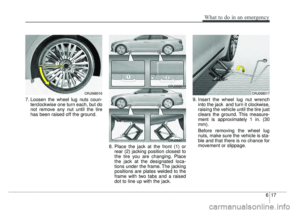
7. Loosen the wheel lug nuts coun-terclockwise one turn each, but do
not remove any nut until the tire
has been raised off the ground.
8. Place the jack at the front (1) orrear (2) jacking position closest to
the tire you are changing. Place
the jack at the designated loca-
tions under the frame. The jacking
positions are plates welded to the
frame with two tabs and a raised
dot to line up with the jack. 9. Insert the wheel lug nut wrench
into the jack and turn it clockwise,
raising the vehicle until the tire just
clears the ground. This measure-
ment is approximately 1 in. (30
mm).
Before removing the wheel lug
nuts, make sure the vehicle is sta-
ble and that there is no chance for
movement or slippage.
ORJ068017ORJ068016
ORJ068014
ORJ068015
Page 444 of 580
What to do in an emergency
18
6
9. Loosen the wheel nuts and
remove them with your fingers.
Slide the wheel off the studs and
lay it flat so it cannot roll away. To
put the wheel on the hub, pick up
the spare tire, line up the holes
with the studs and slide the wheel
onto them. If this is difficult, tip the
wheel slightly and get the top hole
in the wheel lined up with the top
stud. Jiggle the wheel back and
forth until the wheel can slide over
the other studs. Wheels may have sharp edges.
Handle them carefully to avoid possi-
ble severe injury. Before putting the
wheel into place, be sure that there
is nothing on the hub or wheel (such
as mud, tar, gravel, etc.) that pre-
vents the wheel from fitting solidly
against the hub.
10. To install the wheel, hold it on the
studs, put the wheel nuts on the
studs and tighten them finger
tight. Jiggle the tire to be sure it is
completely seated, then tighten
the nuts as much as possible
with your fingers again.
11. Insert the wrench into the jack and lower the vehicle to the
ground by turning the wheel nut
wrench counterclockwise.
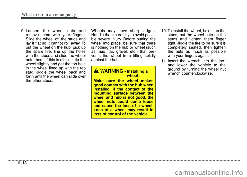
WARNING- Installing a
wheel
Make sure the wheel makes
good contact with the hub when
installed. If the contact of the
mounting surface between the
wheel and hub is not good, the
wheel nuts could come loose
and cause the loss of a wheel.
Loss of a wheel may result in
loss of control of the vehicle.
Page 451 of 580
625
What to do in an emergency
When towing your vehicle in an
emergency without wheel dollies :
1. Set the Engine Start/Stop buttonto ACC position.
2. Place the transmission shift lever in N (Neutral).
3. Release the parking brake.Removable towing hook
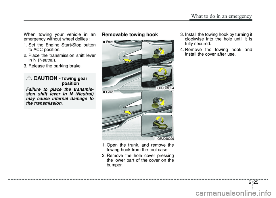
1. Open the trunk, and remove the towing hook from the tool case.
2. Remove the hole cover pressing the lower part of the cover on the
bumper. 3. Install the towing hook by turning it
clockwise into the hole until it is
fully secured.
4. Remove the towing hook and install the cover after use.
CAUTION - Towing gear
position
Failure to place the transmis-sion shift lever in N (Neutral)may cause internal damage tothe transmission.ORJ068024
ORJ068026
■Front
■ Rear
Page 477 of 580
723
Maintenance
ENGINE COOLANT
The high-pressure cooling system
has a reservoir filled with year round
antifreeze coolant. The reservoir is
filled at the factory.
Check the antifreeze protection and
coolant level at least once a year: at
the beginning of the winter season,
and before traveling to a colder cli-
mate.Checking the coolant level Turn the engine off and wait until itcools down. Use extreme care
when removing the radiator cap.
Wrap a thick towel around it, and
turn it counterclockwise slowly to
the first stop. Step back while the
pressure is released from the cool-
ing system.
When you are sure all the pressure
has been released, press down on
the cap, using a thick towel, and
continue turning counterclockwise
to remove it.
Even if the engine is not operating, do not remove the radiator cap or
the drain plug while the engine and
radiator are hot. Hot coolant and
steam may still blow out under
pressure, causing serious injury.
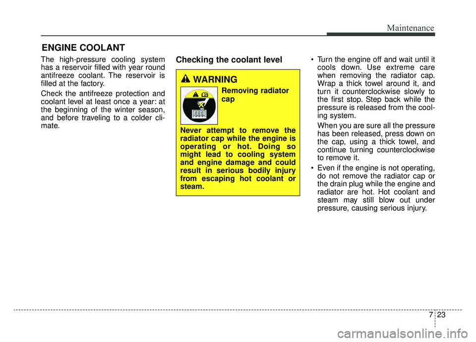
WARNING
Removing radiator
cap
Never attempt to remove the
radiator cap while the engine is
operating or hot. Doing so
might lead to cooling system
and engine damage and could
result in serious bodily injury
from escaping hot coolant or
steam.
Page 510 of 580

Maintenance
56
7
3. Pull the suspected fuse straight
out. Use the removal tool provided
on the engine compartment fuse
panel cover.
4. Check the removed fuse; replace it if it is blown.
Spare fuses are provided in theengine compartment fuse panel.
5. Push in a new fuse of the same rating, and make sure it fits tightly
in the clips.
If it fits loosely, consult an authorized
K900 Kia dealer.
If you do not have a spare, use a fuse of the same rating from a circuityou may not need for operating thevehicle, such as the cigarette lighterfuse.
If the headlights or taillights, stop-
lights, courtesy lamp, day time run-
ning lights (D.R.L) do not work and
the fuses are not blown, check the
fuse panel in the engine compart-
ment. If a fuse is blown, it must be
replaced.
✽ ✽ NOTICE
If the headlamp, turn signal lamp,
or tail lamp malfunction even with-
out any problem to the lamps, have
the vehicle checked by an author-
ized K900 Kia dealer for assistance.
Fuse switch
Always set the fuse switch to the ON
position before using the vehicle.
If you move the switch to the OFF
position, some items such as audio
and digital clock must be reset and
transmitter (or smart key) may not
work properly. When the switch is
Off, the caution indicator will be dis-
played on the instrument cluster.
ORJ078017
ORJ078018
Page 517 of 580
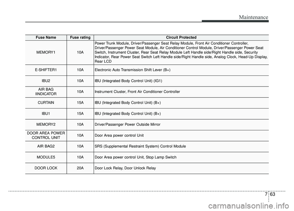
763
Maintenance
Fuse NameFuse ratingCircuit Protected
MEMORY110A
Power Trunk Module, Driver/Passenger Seat Relay Module, Front Air Conditioner Controller,
Driver/Passenger Power Seat Module, Air Conditioner Control Module, Driver/Passenger Power Seat
Switch, Instrument Cluster, Rear Seat Relay Module Left Handle side/Right Handle side, Security
Indicator, Rear Power Seat Switch Left Handle side/Right Handle side, Analog Clock, Head-Up Display,
Rear LCD
E-SHIFTER110AElectronic Auto Transmission Shift Lever (B+)
IBU210AIBU (Integrated Body Control Unit) (IG1)
AIR BAG
IINDICATOR10AInstrument Cluster, Front Air Conditioner Controller
CURTAIN15AIBU (Integrated Body Control Unit) (B+)
IBU115AIBU (Integrated Body Control Unit) (B+)
MEMORY210ADriver/Passenger Power Outside Mirror
DOOR AREA POWER CONTROL UNIT10ADoor Area power control Unit
AIR BAG210ASRS (Supplemental Restraint System) Control Module
MODULE510ADoor Area power control Unit, Stop Lamp Switch
DOOR LOCK20ADoor Lock Relay, Door Unlock Relay
Page 519 of 580
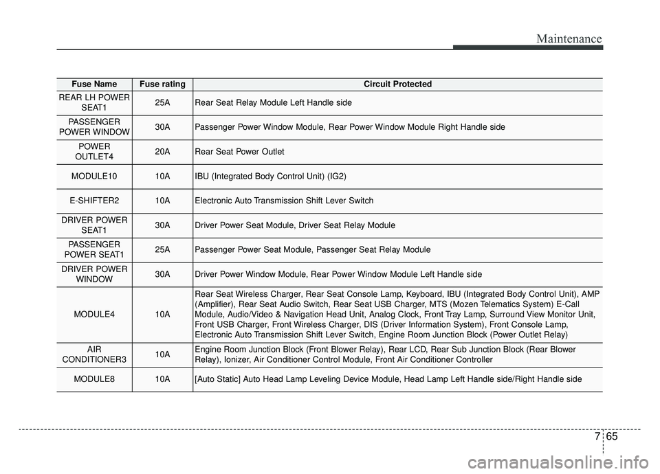
765
Maintenance
Fuse NameFuse ratingCircuit Protected
REAR LH POWERSEAT125ARear Seat Relay Module Left Handle side
PASSENGER
POWER WINDOW30APassenger Power Window Module, Rear Power Window Module Right Handle side
POWER
OUTLET420ARear Seat Power Outlet
MODULE1010AIBU (Integrated Body Control Unit) (IG2)
E-SHIFTER210AElectronic Auto Transmission Shift Lever Switch
DRIVER POWER SEAT130ADriver Power Seat Module, Driver Seat Relay Module
PASSENGER
POWER SEAT125APassenger Power Seat Module, Passenger Seat Relay Module
DRIVER POWER WINDOW30ADriver Power Window Module, Rear Power Window Module Left Handle side
MODULE410A
Rear Seat Wireless Charger, Rear Seat Console Lamp, Keyboard, IBU (Integrated Body Control Unit), AMP
(Amplifier), Rear Seat Audio Switch, Rear Seat USB Charger, MTS (Mozen Telematics System) E-Call
Module, Audio/Video & Navigation Head Unit, Analog Clock, Front Tray Lamp, Surround View Monitor Unit,
Front USB Charger, Front Wireless Charger, DIS (Driver Information System), Front Console Lamp,
Electronic Auto Transmission Shift Lever Switch, Engine Room Junction Block (Power Outlet Relay)
AIR
CONDITIONER310AEngine Room Junction Block (Front Blower Relay), Rear LCD, Rear Sub Junction Block (Rear Blower
Relay), Ionizer, Air Conditioner Control Module, Front Air Conditioner Controller
MODULE810A[Auto Static] Auto Head Lamp Leveling Device Module, Head Lamp Left Handle side/Right Handle side
Page 573 of 580
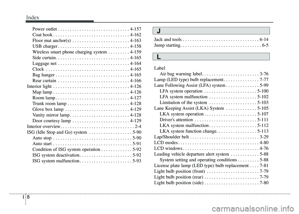
Index
8I
Power outlet . . . . . . . . . . . . . . . . . . . . . . . . . . . . . . 4-157
Coat hook . . . . . . . . . . . . . . . . . . . . . . . . . . . . . . . . 4-162
Floor mat anchor(s) . . . . . . . . . . . . . . . . . . . . . . . . 4-163
USB charger . . . . . . . . . . . . . . . . . . . . . . . . . . . . . . 4-158
Wireless smart phone charging system . . . . . . . . . 4-159
Side curtain. . . . . . . . . . . . . . . . . . . . . . . . . . . . . . . 4-165
Luggage net . . . . . . . . . . . . . . . . . . . . . . . . . . . . . . 4-164
Clock . . . . . . . . . . . . . . . . . . . . . . . . . . . . . . . . . . . 4-\
165
Bag hanger . . . . . . . . . . . . . . . . . . . . . . . . . . . . . . . 4-165
Rear curtain . . . . . . . . . . . . . . . . . . . . . . . . . . . . . . 4-166
Interior light . . . . . . . . . . . . . . . . . . . . . . . . . . . . . . . . 4-126 Map lamp . . . . . . . . . . . . . . . . . . . . . . . . . . . . . . . . 4-126
Room lamp . . . . . . . . . . . . . . . . . . . . . . . . . . . . . . . 4-127
Trunk room lamp . . . . . . . . . . . . . . . . . . . . . . . . . . 4-128
Glove box lamp . . . . . . . . . . . . . . . . . . . . . . . . . . . 4-129
Vanity mirror lamp . . . . . . . . . . . . . . . . . . . . . . . . . 4-128
Door courtesy lamp . . . . . . . . . . . . . . . . . . . . . . . . 4-129
Interior overview. . . . . . . . . . . . . . . . . . . . . . . . . . . . . . . 2-4
ISG (Idle Stop and Go) system . . . . . . . . . . . . . . . . . . 5-90 Auto stop . . . . . . . . . . . . . . . . . . . . . . . . . . . . . . . . . 5-90
Auto start . . . . . . . . . . . . . . . . . . . . . . . . . . . . . . . . . 5-91
Condition of ISG system operation . . . . . . . . . . . . . 5-92
ISG system deactivation . . . . . . . . . . . . . . . . . . . . . . 5-92
ISG system malfunction . . . . . . . . . . . . . . . . . . . . . . 5-93 Jack and tools . . . . . . . . . . . . . . . . . . . . . . . . . . . . . . . . 6-14
Jump starting. . . . . . . . . . . . . . . . . . . . . . . . . . . . . . . . . . 6-5
Label
Air bag warning label. . . . . . . . . . . . . . . . . . . . . . . . 3-76
Lamp (LED type) bulb replacement . . . . . . . . . . . . . . . 7-77
Lane Following Assist (LFA) system . . . . . . . . . . . . . . 5-99 LFA system operation . . . . . . . . . . . . . . . . . . . . . . 5-100
LFA system malfunction . . . . . . . . . . . . . . . . . . . . 5-102
Limitation of the system . . . . . . . . . . . . . . . . . . . . 5-103
Lane Keeping Assist (LKA) System . . . . . . . . . . . . . 5-105 LKA system operation . . . . . . . . . . . . . . . . . . . . . . 5-107
Driver's attention . . . . . . . . . . . . . . . . . . . . . . . . . . 5-111
LKA system malfunction . . . . . . . . . . . . . . . . . . . . 5-112
LKA system function change. . . . . . . . . . . . . . . . . 5-113
Lap/Shoulder belt . . . . . . . . . . . . . . . . . . . . . . . . . . . . . 3-29
LCD modes . . . . . . . . . . . . . . . . . . . . . . . . . . . . . . . . . . 4-80\
LCD windows . . . . . . . . . . . . . . . . . . . . . . . . . . . . . . . . 4-76
Leading vehicle departure alert system . . . . . . . . . . . . 5-88 System setting and operating conditions . . . . . . . . . 5-88
License plate lamp (LED type) bulb replacement . . . . 7-81
Light bulb position (front) . . . . . . . . . . . . . . . . . . . . . . 7-79
Light bulb position (rear) . . . . . . . . . . . . . . . . . . . . . . . 7-79
Light bulb position (side) . . . . . . . . . . . . . . . . . . . . . . . 7-80
L
J