Page 41 of 626

•A lock request is made by the door panel switch while
the door is open.
• When the vehicle security alarm is in pre-arm or armed
status and the liftgate transitions from open to closed.
• When the liftgate transitions from opened to closed and
remote start is active.
When any of these situations occur, after all open doors are
shut, the FOBIK-Safe search will be executed. If it finds a
Passive Entry key fob inside the car, the car will unlock and
alert the customer.
NOTE: The vehicle will only unlock the doors when a valid
Passive Entry key fob is detected inside the vehicle. The
vehicle will not unlock the doors when any of the follow-
ing conditions are true:
• The doors are manually locked using the door lock
knobs.
• Three attempts are made to lock the doors using the
door panel switch and then close the doors.
• There is a valid Passive Entry key fob outside the vehicle
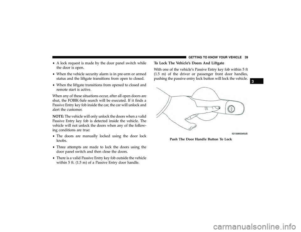
within 5 ft. (1.5 m) of a Passive Entry door handle. To Lock The Vehicle’s Doors And Liftgate
With one of the vehicle’s Passive Entry key fob within 5 ft
(1.5 m) of the driver or passenger front door handles,
pushing the passive entry lock button will lock the vehicle.
Page 116 of 626

WARNING!(Continued)
•Place as much cargo as possible in front of the rear
axle. Too much weight or improperly placed weight
over or behind the rear axle can cause the rear of the
vehicle to sway.
• Do not pile luggage or cargo higher than the top of
the seatback. This could impair visibility or become
a dangerous projectile in a sudden stop or accident.
GARAGE DOOR OPENER — IF EQUIPPED
HomeLink replaces up to three hand-held transmitters that
operate devices such as garage door openers, motorized
gates, lighting or home security systems. The HomeLink
unit is powered by your vehicle’s 12 Volt battery.
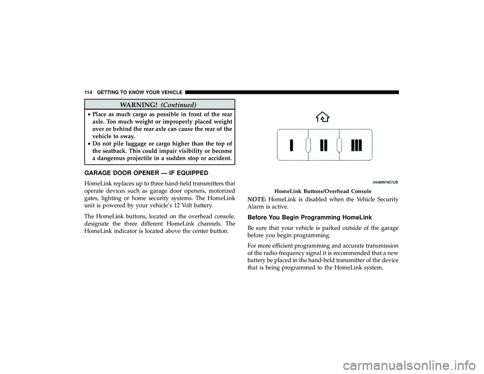
The HomeLink buttons, located on the overhead console,
designate the three different HomeLink channels. The
HomeLink indicator is located above the center button. NOTE:
HomeLink is disabled when the Vehicle Security
Alarm is active.
Before You Begin Programming HomeLink
Be sure that your vehicle is parked outside of the garage
before you begin programming.
For more efficient programming and accurate transmission
of the radio-frequency signal it is recommended that a new
battery be placed in the hand-held transmitter of the device
that is being programmed to the HomeLink system.
Page 121 of 626
Security
It is advised to erase all channels before you sell or turn in
your vehicle.
To do this, push and hold the two outside buttons for 20
seconds until the orange indicator flashes. Note that all
channels will be erased. Individual channels cannot be
erased.
The HomeLink Universal Transceiver is disabled when the
Vehicle Security Alarm is active.
Troubleshooting Tips
If you are having trouble programming HomeLink, here
are some of the most common solutions:
•Replace the battery in the Garage Door Opener hand-
held transmitter.
• Push the LEARN button on the Garage Door Opener to
complete the training for a Rolling Code.
• Did you unplug the device for programming and re-
member to plug it back in? If you have any problems, or require assistance, please call
toll-free 1-800-355-3515 or, on the Internet at
HomeLink.com for information or assistance.
Page 149 of 626

The electrical loads that may be switched off (if equipped),
and vehicle functions which can be effected by load
reduction:
•Heated Seat/Vented Seats/Heated Wheel
• Rear Defroster And Heated Mirrors
• HVAC System
• 150W Power Inverter System
• Audio and Telematics System
Loss of the battery charge may indicate one or more of the
following conditions:
• The charging system cannot deliver enough electrical
power to the vehicle system because the electrical loads
are larger than the capability of charging system. The
charging system is still functioning properly.
• Turning on all possible vehicle electrical loads (e.g.
HVAC to max settings, exterior and interior lights,
overloaded power outlets +12V, 150W, USB ports) dur-
ing certain driving conditions (city driving, towing,
frequent stopping).
• Installing options like additional lights, upfitter electri-
cal accessories, audio systems, alarms and similar de-
vices. •
Unusual driving cycles (short trips separated by long
parking periods).
• The vehicle was parked for an extended period of time
(weeks, months).
• The battery was recently replaced and was not charged
completely.
• The battery was discharged by an electrical load left on
when the vehicle was parked.
• The battery was used for an extended period with the
engine not running to supply radio, lights, chargers,
+12V portable appliances like vacuum cleaner ’s, game
consoles and similar devices.
What to do when an electrical load reduction action
message is present (“Battery Saver On” or “Battery Saver
Mode”)
During a trip:
• Reduce power to unnecessary loads if possible:
– Turn off redundant lights (interior or exterior)
– Check what may be plugged in to power outlets +12V, 150W, USB ports
– Check HVAC settings (blower, temperature)
– Check the audio settings (volume)
4
GETTING TO KNOW YOUR INSTRUMENT PANEL 147
Page 150 of 626

After a trip:
•Check if any aftermarket equipment was installed (ad-
ditional lights, upfitter electrical accessories, audio sys-
tems, alarms) and review specifications if any (load and
Ignition Off Draw currents).
• Evaluate the latest driving cycles (distance, driving time
and parking time).
• The vehicle should have service performed if the mes-
sage is still present during consecutive trips and the
evaluation of the vehicle and driving pattern did not
help to identify the cause.
TRIP COMPUTER
Push and release the up or down arrow button until the
Trip A or Trip B icon is highlighted in the instrument
cluster display (Toggle left or right to select Trip A or Trip
B). Push and release the OK button to display the Trip
information. Trip A
•
Shows the total distance traveled for Trip A since the last
reset.
• Shows the elapsed time traveled for Trip A since the last
reset.
Trip B
• Shows the total distance traveled for Trip B since the last
reset.
• Shows the elapsed time traveled for Trip B since the last
reset.
Elapsed Time
Shows the total elapsed time of travel since the last reset
when the ignition switch is in the ACC position. Elapsed
time will increment when the ignition switch is in the ON
or START position.
To Reset A Trip Function
Reset will only occur while a resettable function is selected
(highlighted). Push and hold the OKbutton to clear the
resettable function being displayed.
148 GETTING TO KNOW YOUR INSTRUMENT PANEL
Page 155 of 626
— Transmission Temperature Warning Light — If
Equipped
This warning light will illuminate to warn of a high
transmission fluid temperature. This may occur with
strenuous usage such as trailer towing. If this light turns
on, stop the vehicle and run the engine at idle or slightly
faster, with the transmission in PARK or NEUTRAL, until
the light turns off. Once the light turns off, you may
continue to drive normally.
CAUTION!
Continuous driving with the Transmission Tempera-
ture Warning Light illuminated will eventually cause
severe transmission damage or transmission failure.
— Vehicle Security Warning Light — If Equipped
This light will flash at a fast rate for approximately 15
seconds when the vehicle security alarm is arming, and
then will flash slowly until the vehicle is disarmed.
Yellow Warning Lights
Page 189 of 626
(8 km/h), to objects moving a maximum of approximately
20 mph (32 km/h), such as in parking lot situations.
NOTE:In a parking lot situation, oncoming vehicles can be
obscured by vehicles parked on either side. If the sensors
are blocked by other structures or vehicles, the system will
not be able to alert the driver.
When RCP is on and the vehicle is in REVERSE, the driver
is alerted using both the visual and audible alarms, includ-
ing reducing the radio volume.
Page 283 of 626

Entry/Exit Mode, press the “Up” button once while in
Entry/Exit Mode or drive the vehicle over 15 mph
(24 km/h).
NOTE: Automatic lowering of the vehicle into Entry/Exit
Mode can be enabled through the Uconnect Touch-Screen
Radio. If this feature is enabled, the vehicle will only lower
if the gear selector is in �PARK�, the terrain switch is in
�AUTO�, the transfer-case is in �AUTO” and the vehicle
level should be either in Normal or Aero Mode. The Vehicle
will not automatically lower if the air suspension level is in
Off Rd 2 or Off Rd 1. If the vehicle is equipped with
Intrusion Theft Module (ITM), the lowering will be sup-
pressed when the ignition is switched OFF and the door is
open to prevent setting the alarm off.
The Selec-Terrain switch will automatically change the
vehicle to the proper height based on the position of the
Selec-Terrain switch. The height can be changed from the
default Selec-Terrain setting by normal use of the air
suspension buttons. Refer to “Selec-Terrain” in “Starting
And Operating” for further information.
The system requires that the engine be running for all
changes. When lowering the vehicle all of the doors,
including the liftgate, must be closed. If a door is opened at any time while the vehicle is lowering the change will not
be completed until the open door(s) is/are closed.
The Quadra-Lift air suspension system uses a lifting and
lowering pattern which keeps the headlights from incor-
rectly shining into oncoming traffic. When raising the
vehicle, the rear of the vehicle will move up first and then
the front. When lowering the vehicle, the front will move
down first and then the rear.
After the engine is turned off, it may be noticed that the air
suspension system operates briefly, this is normal. The
system is correcting the position of the vehicle to ensure a
proper appearance.
To assist with changing a spare tire, the Quadra-Lift air
suspension system has a feature which allows the auto-
matic leveling to be disabled. Refer to “Uconnect Settings”
in “Multimedia” for further information.
For further information refer to “Driving Tips” in “Starting
And Operating” section.
NOTE:
If equipped with a touch screen radio all enabling/
disabling of air suspension features must be done through
the radio. Refer to “Uconnect Settings” in “Multimedia” for
further information.
6
STARTING AND OPERATING 281