2019 Hyundai Tucson tow
[x] Cancel search: towPage 219 of 685
3-127
Convenient features of your vehicle
3
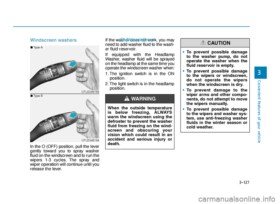
Windscreen washers
In the O (OFF) position, pull the lever
gently toward you to spray washer
fluid on the windscreen and to run the
wipers 1-3 cycles. The spray and
wiper operation will continue until you
release the lever.If the washer does not work, you may
need to add washer fluid to the wash-
er fluid reservoir.
If equipped with the Headlamp
Washer, washer fluid will be sprayed
on the headlamp at the same time you
operate the windscreen washer when:
1. The ignition switch is in the ON
position.
2. The light switch is in the headlamp position.
When the outside temperature
is below freezing, ALWAYS
warm the windscreen using the
defroster to prevent the washer
fluid from freezing on the wind-
screen and obscuring your
vision which could result in an
accident and serious injury or
death.
WARNING
• To prevent possible damage
to the washer pump, do not
operate the washer when the
fluid reservoir is empty.
• To prevent possible damage
to the wipers or windscreen,
do not operate the wipers
when the windscreen is dry.
• To prevent damage to the
wiper arms and other compo-
nents, do not attempt to move
the wipers manually.
• To prevent possible damage
to the wipers and washer sys-
tem, use anti-freezing washer
fluids in the winter season or
cold weather.
CAUTION
OTLE045163
OTLE045164
■ Type A
■Type B
TLe UK 3b(110~).qxp 6/12/2018 2:36 PM Page 127
Page 234 of 685
3-142
Convenient features of your vehicle
Defrost-Level (A, D)
Most of the air flow is directed to the
windscreen.
Face-Level (B, D, F)
Air flow is directed toward the upper
body and face. Additionally, each
outlet can be controlled to direct the
air discharged from the outlet.
Floor-Level (A, C, D, E, F)
Most of the air flow is directed to the
floor.
Also you may select 2~3 modes at
the same time.
- face ( ) + floor ( ) mode
- face ( ) + defrost ( ) mode
- floor ( ) + defrost ( ) mode
- face ( ) + floor ( ) + defrost( ) mode
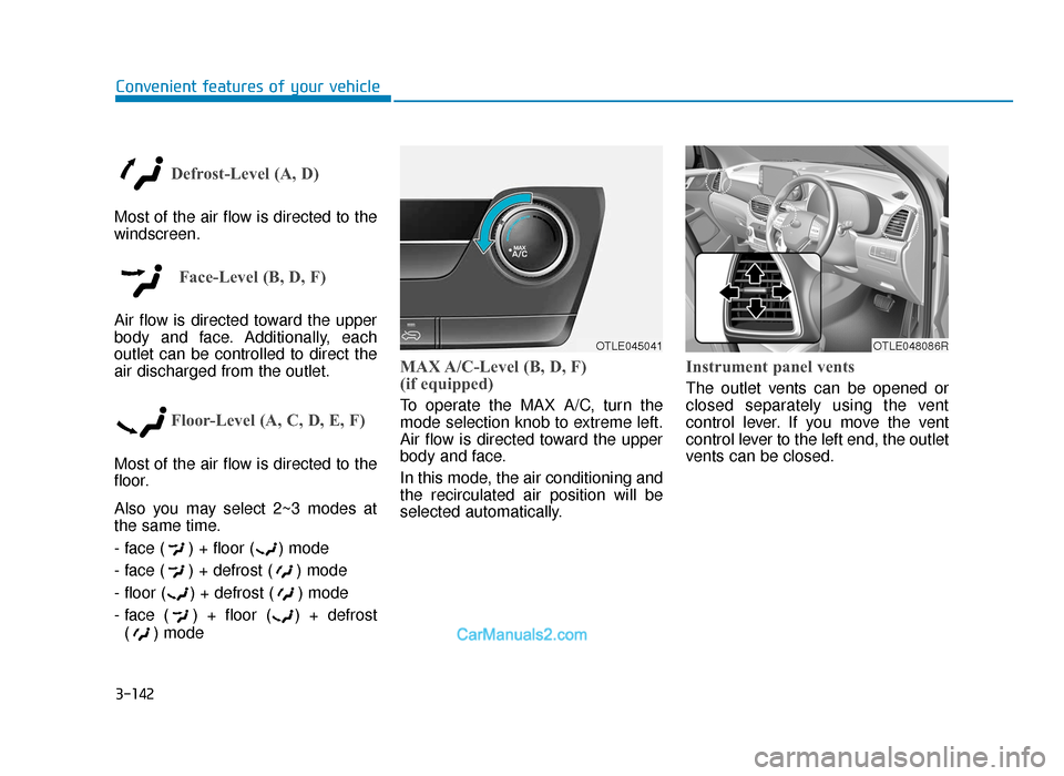
MAX A/C-Level (B, D, F)
(if equipped)
To operate the MAX A/C, turn the
mode selection knob to extreme left.
Air flow is directed toward the upper
body and face.
In this mode, the air conditioning and
the recirculated air position will be
selected automatically.
Instrument panel vents
The outlet vents can be opened or
closed separately using the vent
control lever. If you move the vent
control lever to the left end, the outlet
vents can be closed.
OTLE045041OTLE048086R
TLe UK 3b(110~).qxp 6/12/2018 2:38 PM Page 142
Page 245 of 685
3-153
Convenient features of your vehicle
3
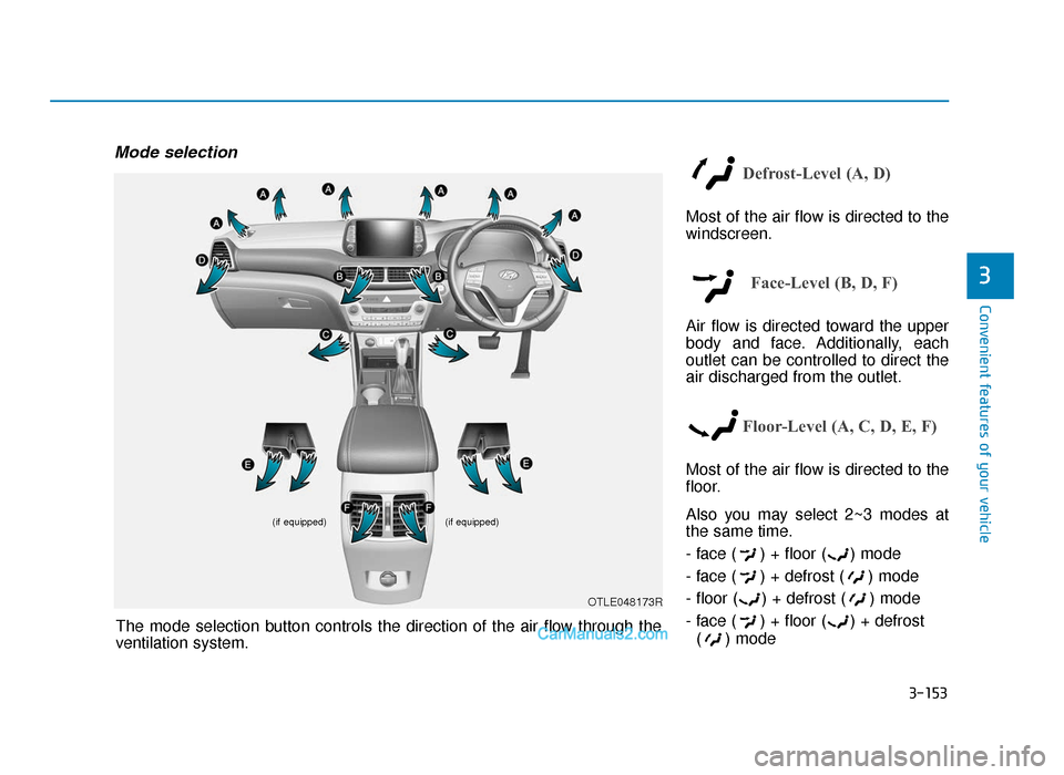
Mode selection
Defrost-Level (A, D)
Most of the air flow is directed to the
windscreen.
Face-Level (B, D, F)
Air flow is directed toward the upper
body and face. Additionally, each
outlet can be controlled to direct the
air discharged from the outlet.
Floor-Level (A, C, D, E, F)
Most of the air flow is directed to the
floor.
Also you may select 2~3 modes at
the same time.
- face ( ) + floor ( ) mode
- face ( ) + defrost ( ) mode
- floor ( ) + defrost ( ) mode
- face ( ) + floor ( ) + defrost( ) mode
(if equipped)
(if equipped)
OTLE048173R
The mode selection button controls the direction of the air flow through the
ventilation system.
TLe UK 3b(110~).qxp 6/12/2018 2:39 PM Page 153
Page 258 of 685
3-166
Convenient features of your vehicle
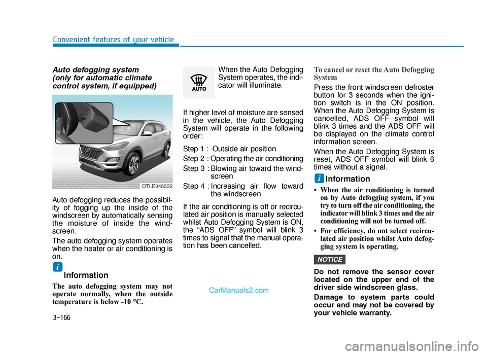
Auto defogging system (only for automatic climate control system, if equipped)
Auto defogging reduces the possibil-
ity of fogging up the inside of the
windscreen by automatically sensing
the moisture of inside the wind-
screen.
The auto defogging system operates
when the heater or air conditioning is
on.
Information
The auto defogging system may not
operate normally, when the outside
temperature is below -10 °C. When the Auto Defogging
System operates, the indi-
cator will illuminate.
If higher level of moisture are sensed
in the vehicle, the Auto Defogging
System will operate in the following
order:
Step 1 : Outside air position
Step 2 : Operating the air conditioning
Step 3 : Blowing air toward the wind- screen
Step 4 : Increasing air flow toward the windscreen
If the air conditioning is off or recircu-
lated air position is manually selected
whilst Auto Defogging System is ON,
the “ADS OFF” symbol will blink 3
times to signal that the manual opera-
tion has been cancelled.
To cancel or reset the Auto Defogging
System
Press the front windscreen defroster
button for 3 seconds when the igni-
tion switch is in the ON position.
When the Auto Defogging System is
cancelled, ADS OFF symbol will
blink 3 times and the ADS OFF will
be displayed on the climate control
information screen.
When the Auto Defogging System is
reset, ADS OFF symbol will blink 6
times without a signal.
Information
• When the air conditioning is turned on by Auto defogging system, if you
try to turn off the air conditioning, the
indicator will blink 3 times and the air
conditioning will not be turned off.
• For efficiency, do not select recircu- lated air position whilst Auto defog-
ging system is operating.
Do not remove the sensor cover
located on the upper end of the
driver side windscreen glass.
Damage to system parts could
occur and may not be covered by
your vehicle warranty.
NOTICE
i
i
OTLE048332
TLe UK 3b(110~).qxp 6/12/2018 2:41 PM Page 166
Page 272 of 685
3-180
Convenient features of your vehicle
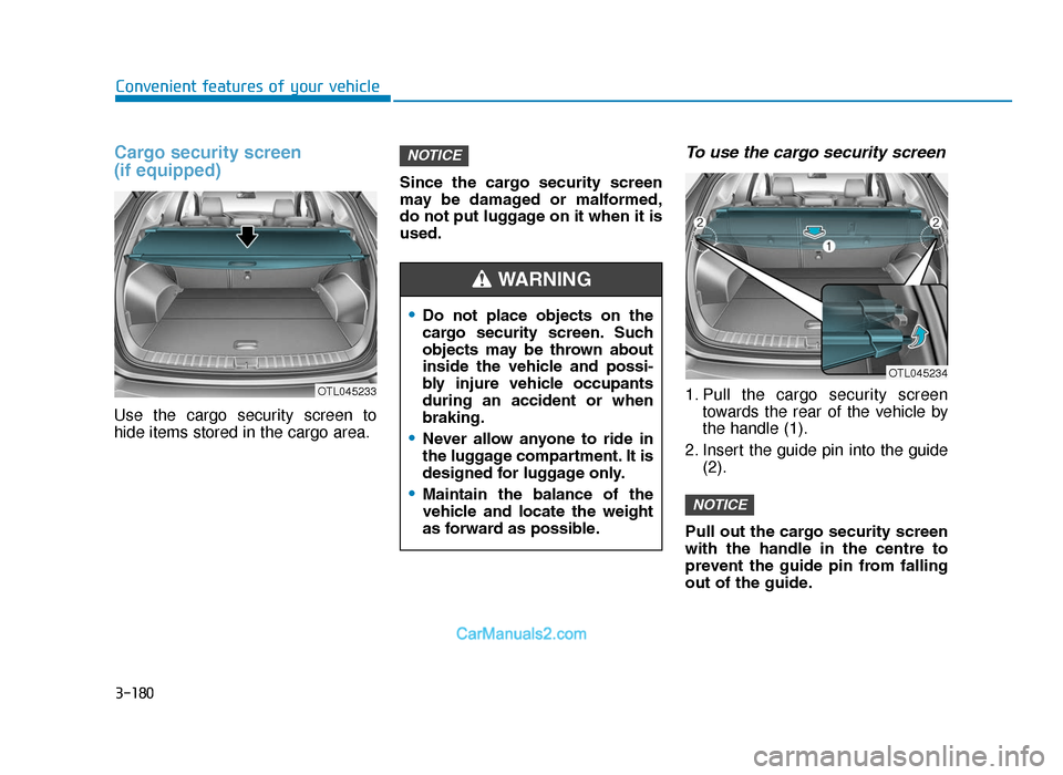
Cargo security screen
(if equipped)
Use the cargo security screen to
hide items stored in the cargo area.Since the cargo security screen
may be damaged or malformed,
do not put luggage on it when it is
used.
To use the cargo security screen
1. Pull the cargo security screen
towards the rear of the vehicle by
the handle (1).
2. Insert the guide pin into the guide (2).
Pull out the cargo security screen
with the handle in the centre to
prevent the guide pin from falling
out of the guide.
NOTICE
NOTICE
OTL045233
OTL045234
•Do not place objects on the
cargo security screen. Such
objects may be thrown about
inside the vehicle and possi-
bly injure vehicle occupants
during an accident or when
braking.
•Never allow anyone to ride in
the luggage compartment. It is
designed for luggage only.
•Maintain the balance of the
vehicle and locate the weight
as forward as possible.
WARNING
TLe UK 3b(110~).qxp 6/12/2018 2:42 PM Page 180
Page 281 of 685
4-6
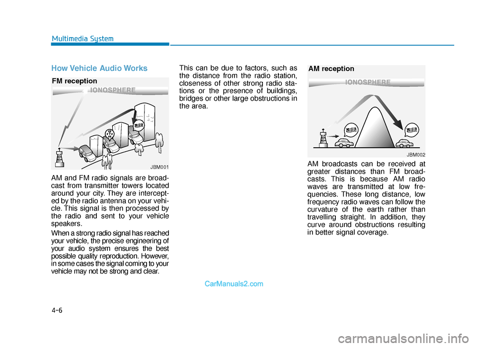
How Vehicle Audio Works
AM and FM radio signals are broad-
cast from transmitter towers located
around your city. They are intercept-
ed by the radio antenna on your vehi-
cle. This signal is then processed by
the radio and sent to your vehicle
speakers.
When a strong radio signal has reached
your vehicle, the precise engineering of
your audio system ensures the best
possible quality reproduction. However,
in some cases the signal coming to your
vehicle may not be strong and clear.This can be due to factors, such as
the distance from the radio station,
closeness of other strong radio sta-
tions or the presence of buildings,
bridges or other large obstructions in
the area.
AM broadcasts can be received at
greater distances than FM broad-
casts. This is because AM radio
waves are transmitted at low fre-
quencies. These long distance, low
frequency radio waves can follow the
curvature of the earth rather than
travelling straight. In addition, they
curve around obstructions resulting
in better signal coverage.
Multimedia System
JBM001
FM reception
JBM002
AM reception
TLe UK 4.qxp 5/10/2018 12:04 PM Page 6
Page 327 of 685
Driving your vehicle
Smart cruise control (SCC) with stop & go
system..................................................................\
5-142
Smart Cruise Control Switch ......................................5-142
Smart Cruise Control speed........................................5-143
Smart Cruise Control Vehicle-to-Vehicle
Distance ........................................................................\
...5-149
Sensor to detect distance to the vehicle ahead ...5-152
To adjust the sensitivity of Smart Cruise
Control ........................................................................\
.....5-154
To convert to Cruise Control mode ..........................5-155
Limitations of the system ...........................................5-155
Special driving conditions .................................5-160
Hazardous driving conditions ....................................5-160
Rocking the vehicle ......................................................5-160
Smooth cornering .........................................................5-161
Driving at night ..............................................................5-161
Driving in the rain .........................................................5-161
Driving in flooded areas..............................................5-162
Highway driving .............................................................5-162
Reducing the risk of a rollover .................................5-163
Winter driving .....................................................5-164
Snow or icy conditions ................................................5-164
Winter Precautions .......................................................5-166
Trailer towing .....................................................5-169
If you decide to pull a trailer?...................................5-170
Trailer towing equipment ............................................5-173
Driving with a trailer ....................................................5-174
Maintenance when towing a trailer .........................5-178
Vehicle weight ....................................................5-179
Overloading ....................................................................5-17\
9
5
TLe UK 5.qxp 5/10/2018 12:18 PM Page 3
Page 331 of 685
5-7
Driving your vehicle
5
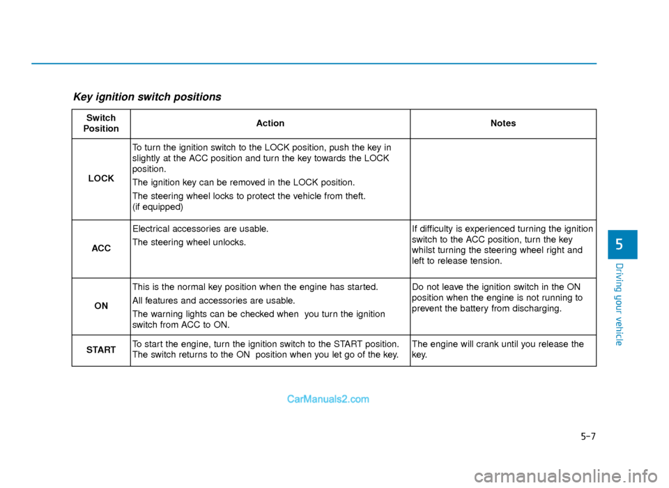
Key ignition switch positions
Switch
PositionActionNotes
LOCK
To turn the ignition switch to the LOCK position, push the key in
slightly at the ACC position and turn the key towards the LOCK
position.
The ignition key can be removed in the LOCK position.
The steering wheel locks to protect the vehicle from theft.
(if equipped)
ACC
Electrical accessories are usable.
The steering wheel unlocks.If difficulty is experienced turning the ignition
switch to the ACC position, turn the key
whilst turning the steering wheel right and
left to release tension.
ON
This is the normal key position when the engine has started.
All features and accessories are usable.
The warning lights can be checked when you turn the ignition
switch from ACC to ON.Do not leave the ignition switch in the ON
position when the engine is not running to
prevent the battery from discharging.
STARTTo start the engine, turn the ignition switch to the START position.
The switch returns to the ON position when you let go of the key.The engine will crank until you release the
key.
TLe UK 5.qxp 5/10/2018 12:19 PM Page 7