2019 Hyundai Santa Fe oil pan
[x] Cancel search: oil panPage 247 of 557
3-158
Convenient features of your vehicle
Have the cabin air filter replaced by
an authorized HYUNDAI dealer
according to the maintenance sched-
ule. If the vehicle is being driven in
severe conditions such as dusty or
rough roads and/or if transporting
pets or occupants smoke inside the
vehicle, then more frequent cabin air
filter inspections and changes are
required.
If the air flow rate suddenly decreas-
es, the system should be checked at
an authorized HYUNDAI dealer.
Checking the amount of air conditioner refrigerant andcompressor lubricant
When the amount of refrigerant is
low, the performance of the air con-
ditioning is reduced. Overfilling also
reduces the performance of the air
conditioning system.
Therefore, if abnormal operation is
found, have the system inspected by
an authorized HYUNDAI dealer. It is important that the correct
type and amount of oil and refrig-
erant is used. Otherwise, damage
to the compressor and abnormal
system operation may occur.
The air conditioning system should
be serviced by an authorized
HYUNDAI dealer.
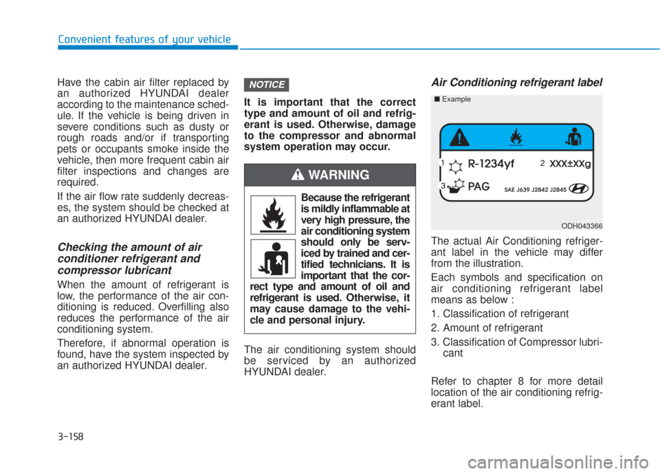
Air Conditioning refrigerant label
The actual Air Conditioning refriger-
ant label in the vehicle may differ
from the illustration.
Each symbols and specification on
air conditioning refrigerant label
means as below :
1. Classification of refrigerant
2. Amount of refrigerant
3. Classification of Compressor lubri-
cant
Refer to chapter 8 for more detail
location of the air conditioning refrig-
erant label.
NOTICE
ODH043366
■ Example
Because the refrigerant
is mildly inflammable at
very high pressure, the
air conditioning system
should only be serv-
iced by trained and cer-
tified technicians. It is
important that the cor-
rect type and amount of oil and
refrigerant is used. Otherwise, it
may cause damage to the vehi-
cle and personal injury.
WARNING
Page 277 of 557

5-3
Driving your vehicle
5
Carbon monoxide (CO) gas is toxic. Breathing CO can cause unconsciousness and death.
Engine exhaust contains carbon monoxide which cannot be seen or smelled.
Do not inhale engine exhaust.
If at any time you smell engine exhaust inside the vehicle, open the windows immediately. Exposure to CO can cause
unconsciousness and death by asphyxiation.
Be sure the exhaust system does not leak.
The exhaust system should be checked whenever the vehicle is raised to change the oil or for any other purpose. If
you hear a change in the sound of the exhaust or if you drive over something that strikes the underneath side of the
vehicle, have the exhaust system checked as soon as possible by an authorized HYUNDAI dealer.
Do not run the engine in an enclosed area.
Letting the engine idle in your garage, even with the garage door open, is a hazardous practice. Run the engine only
long enough to start the engine and to move the vehicle out of the garage.
Avoid idling the engine for prolonged periods with people inside the vehicle.
If it is necessary to idle the engine for a prolonged period with people inside the vehicle, be sure to do so only in an
open area with the air intake set at "Fresh" and fan control set to high so fresh air is drawn into the interior.
Keep the air intakes clear.
To assure proper operation of the ventilation system, keep the ventilation air intakes located in front of the windshield
clear of snow, ice, leaves, or other obstructions.
If you must drive with the liftgate open:
Close all windows.
Open instrument panel air vents.
Set the air intake control at "Fresh", the air flow control at "Floor" or "Face", and the fan control set to high.
WARNING
Page 413 of 557
5-139
Driving your vehicle
5
5. Start the vehicle, apply the brakes,shift to neutral, release the park-
ing brake and slowly release the
brakes until the trailer chocks
absorb the load.
6. Reapply the brakes and parking brakes.
7. Move the shift lever to P (Park).
8. Shut off the vehicle and release the vehicle brakes but leave the
parking brake set.Driving the vehicle after it hasbeen parked on a hill
1. With the gear shift lever in P
(Park), apply the brakes and hold
the brake pedal down while per-
forming the following:
and
2. Slowly remove your foot from the brake pedal.
3. Drive slowly until the trailer is clear of the chocks.
4. Stop and have someone pick up and store the chocks.
Maintenance when trailer tow-
ing
Your vehicle will need service more
often when you regularly pull a trail-
er. Important items to pay particular
attention to include engine oil, auto-
matic transmission fluid, axle lubri-
cant and cooling system fluid. Brake
condition is another important item to
frequently check. If you’re trailering,
it’s a good idea to review these items
before you start your trip. Don't forget
to also maintain your trailer and
hitch. Follow the maintenance sched-
ule that accompanied your trailer and
check it periodically. Preferably,
inspect the vehicle and trailer at the
start of each day's driving. Inspect
the hitch mounting to make sure the
hitch is properly secured to the vehi-
cle. Inspect the trailer electrical
wiring to make sure brake lights, turn
signal lights, running lights, and haz-
ard lights are working properly.
Do not get out of the vehicle
without the parking brake
firmly set. If you have left the
engine running, the vehicle
can move suddenly. You and
others could be seriously or
fatally injured.
Do not apply the accelerator
pedal to hold the vehicle on
an uphill.
WARNING
Page 463 of 557
7-21
7
Maintenance
E
EN
N G
GI
IN
N E
E
O
O I
IL
L
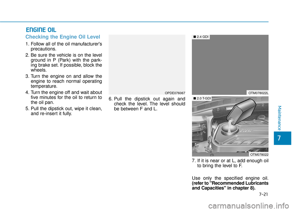
Checking the Engine Oil Level
1. Follow all of the oil manufacturer's
precautions.
2. Be sure the vehicle is on the level ground in P (Park) with the park-
ing brake set. If possible, block the
wheels.
3. Turn the engine on and allow the engine to reach normal operating
temperature.
4. Turn the engine off and wait about five minutes for the oil to return to
the oil pan.
5. Pull the dipstick out, wipe it clean, and re-insert it fully. 6. Pull the dipstick out again and
check the level. The level should
be between F and L.
7. If it is near or at L, add enough oilto bring the level to F.
Use only the specified engine oil.
(refer to "Recommended Lubricants
and Capacities" in chapter 8).
OPDE076067OTM078022L
OTM078022
■ 2.4 GDI
■2.0 T-GDI
Page 494 of 557
F
FU
U S
SE
E S
S
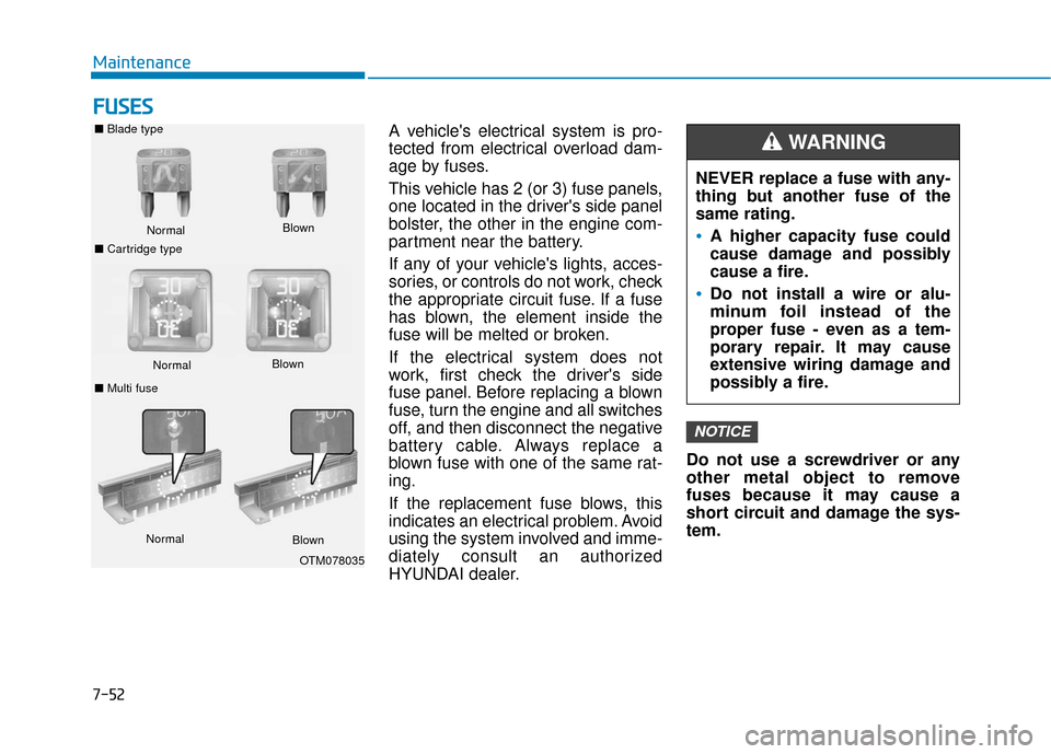
A vehicle's electrical system is pro-
tected from electrical overload dam-
age by fuses.
This vehicle has 2 (or 3) fuse panels,
one located in the driver's side panel
bolster, the other in the engine com-
partment near the battery.
If any of your vehicle's lights, acces-
sories, or controls do not work, check
the appropriate circuit fuse. If a fuse
has blown, the element inside the
fuse will be melted or broken.
If the electrical system does not
work, first check the driver's side
fuse panel. Before replacing a blown
fuse, turn the engine and all switches
off, and then disconnect the negative
battery cable. Always replace a
blown fuse with one of the same rat-
ing.
If the replacement fuse blows, this
indicates an electrical problem. Avoid
using the system involved and imme-
diately consult an authorized
HYUNDAI dealer. Do not use a screwdriver or any
other metal object to remove
fuses because it may cause a
short circuit and damage the sys-
tem.
NOTICE
NEVER replace a fuse with any-
thing but another fuse of the
same rating.
A higher capacity fuse could
cause damage and possibly
cause a fire.
Do not install a wire or alu-
minum foil instead of the
proper fuse - even as a tem-
porary repair. It may cause
extensive wiring damage and
possibly a fire.
WARNING ■
Blade type
Normal
■ Cartridge type Blown
Normal
Blown
■ Multi fuse
Normal Blown
OTM078035
Maintenance
7-52
Page 503 of 557

Engine compartment fuse panel
Fuse NameFuse RatingProtected Component
FUSE
INVERTER30AAC Inverter Unit
POWER TAILGATE30APower Tail Gate Module
TRAILER 330ATrailer Lamp
IG240AStart Relay, ICU Junction Block (Fuse - A/C, WASHER, WIPER (REAR), MODULE 1,
MODULE 2, REAR A/C)
OIL PUMP40AElectronic Oil Pump Module
COOLING FAN 250ACooling Fan Relay
HEATED MIRROR10ADriver/Passenger Power Outside Mirror, A/C Control Module
A/C 210AA/C Control Module
WIPER FRT 210AWiper (LO) Relay, Front Wiper Motor
ECU 415APCM
AMS10ABattery Sensor
VACUUM PUMP20AVacuum Pump
4WD20AAWD ECM
Maintenance
7
7-61
Page 504 of 557
![Hyundai Santa Fe 2019 Owners Manual Engine compartment fuse panel
Fuse NameFuse RatingProtected Component
PCB Block
SENSOR 615AElectronic Oil Pump Module, [2.0 T-GDI] Vacuum Pump
ABS 310AESC Module
SENSOR 710ASmart Cruise Control Radar
Hyundai Santa Fe 2019 Owners Manual Engine compartment fuse panel
Fuse NameFuse RatingProtected Component
PCB Block
SENSOR 615AElectronic Oil Pump Module, [2.0 T-GDI] Vacuum Pump
ABS 310AESC Module
SENSOR 710ASmart Cruise Control Radar](/manual-img/35/16316/w960_16316-503.png)
Engine compartment fuse panel
Fuse NameFuse RatingProtected Component
PCB Block
SENSOR 615AElectronic Oil Pump Module, [2.0 T-GDI] Vacuum Pump
ABS 310AESC Module
SENSOR 710ASmart Cruise Control Radar
SENSOR 510ACanister Close Valve, E/R Junction Block (Cooling Fan Relay)
IGN COIL20AIgnition Coil #1/#2/#3/#4
SENSOR 110A
[2.4 GDI] Fuel Pump Relay, Variable Intake Solenoid Valve, Purge Control Solenoid
Valve, Oil Control Valve
[2.0 T-GDI] Fuel Pump Relay, RCV Control Solenoid Valve, Purge Control Solenoid
Valve, Oil Control Valve
E-CVVT 220APCM
A/C 110A[2.4 GDI] A/CON Relay
WIPER FRT 125AWiper Main Relay
TCU 210ATransmission Range Switch
ECU 310APCM
B/ALARM HORN15ABurglar Alarm Horn Relay, Horn Relay
Maintenance
7-62
Page 548 of 557
I-5
Electric Power Steering (EPS) ........................................3-28
Electrochromic mirror (ECM) ........................................3-32
Electronic child safety lock system ................................3-19
Electronic Stability Control (ESC) .................................5-32
Emission control system .................................................7-84Crankcase emission control system ...........................7-84
Evaporative emission control System ........................7-84
Exhaust emission control system ...............................7-85
Engine compartment..................................................1-7, 7-3
Engine compartment panel fuse replacement .................7-54
Engine coolant ................................................................7-23
Engine coolant temperature gauge .................................3-70
Engine number ................................................................8-11
Engine oil ........................................................................\
7-21
Engine specification..........................................................8-2
Engine Start/Stop button ...................................................5-9
EPB (Electronic Parking Brake) .....................................5-21
Evaporative emission control System.............................7-84
Event Data Recorder (EDR) ...........................................F-10
Exhaust emission control system....................................7-85
Explanation of scheduled maintenance items.................7-18
Exterior care....................................................................7-76\
Exterior overview Front view ....................................................................1-2
Rear view......................................................................1-\
3 Flat tire ........................................................................\
....6-14
Changing tires ............................................................6-16
Floor mat anchor(s).......................................................3-176
Fluid Brake fluid ..................................................................7-26
Washer fluid ...............................................................7-27
Forward Collision-Avoidance Assist (FCA) system ......5-54
Four Wheel Drive (4WD), see All Wheel Drive (AWD) .. 5-40
Front fog lamp ..............................................................3-120
Front seat adjustment ........................................................2-6 Manual adjustment .......................................................2-6
Power adjustment .........................................................2-9
Front seat head restraints ................................................2-18 Adjusting the height up and down .............................2-18
Removal/Reinstallation ..............................................2-19
Fuel filler door ................................................................3-64
Fuel gauge .......................................................................3\
-71
Fuel requirements .............................................................F-7 Fuel additives ...............................................................F-8
Fuses ........................................................................\
.......7-52 Blade type fuse ...........................................................7-54
Cartridge type fuse .....................................................7-54
Engine compartment panel fuse replacement ............7-54
Fuse/relay panel description .......................................7-55
Instrument panel fuse replacement.............................7-53
Multi fuse ...................................................................7-54
I
Index
EF