2019 Hyundai Kona EV display
[x] Cancel search: displayPage 372 of 540

6-16
What to do in an emergency
1. Speed restriction label
2. Sealant bottle and label with speed restriction
3. Filling hose from sealant bottle to wheel
4. Connectors and cable for power outlet direct connection 5. Holder for the sealant bottle
6. Compressor
7. ON/OFF switch
8. Pressure gauge for displaying the
tire inflation pressure
9. Button for reducing tire inflation pressure Connectors, cable and connection
hose are stored in the compressor
housing.
Strictly follow the specified sequence,
otherwise the sealant may escape
under high pressure.
Components of the Tire Mobility Kit
ODE067044
Do not use the tire sealant after
the sealant has expired (i.e.
pasted the expiration date on
the sealant container). This can
increase the risk of tire failure.
WARNING
Keep out of reach of children.
Avoid contact with eyes.
Do not swallow.
WARNING
Page 413 of 540

7-33
7
Maintenance
Tire speed ratings
The chart below lists many of the dif-
ferent speed ratings currently being
used for passenger car tires. The
speed rating is part of the tire size
designation on the sidewall of the
tire. This symbol corresponds to that
tire’s designed maximum safe oper-
ating speed.
3. Checking tire life (TIN : TireIdentification Number)
Any tires that are over six years old,
based on the manufacturing date,
(including the spare tire) should be
replaced by new ones. You can find
the manufacturing date on the tire
sidewall (possibly on the inside of the
wheel), displaying the DOT Code.
The DOT Code is a series of num-
bers on a tire consisting of numbers
and English letters. The manufactur-
ing date is designated by the last four
digits (characters) of the DOT code.
DOT : XXXX XXXX OOOO
The front part of the DOT means a
plant code number, tire size and
tread pattern and the last four num-
bers indicate week and year manu-
factured.
For example:
DOT XXXX XXXX 1418 represents
that the tire was produced in the 14th
week of 2018.
4. Tire ply composition andmaterial
The number of layers or plies of rub-
ber-coated fabric in the tire. Tire
manufacturers also must indicate the
materials in the tire, which include
steel, nylon, polyester, and others.
The letter "R" means radial ply con-
struction; the letter "D" means diago-
nal or bias ply construction; and the
letter "B" means belted-bias ply con-
struction.
5. Maximum permissible infla-tion pressure
This number is the greatest amount
of air pressure that should be put in
the tire. Do not exceed the maximum
permissible inflation pressure. Refer
to the Tire and Loading Information
label for recommended inflation
pressure.
Speed
Rating
Symbol Maximum Speed
S 112 mph (180 km/h) T 118 mph (190 km/h)
H 130 mph (210 km/h) V 149 mph (240 km/h)
W 168 mph (270 km/h)
Y186 mph (300 km/h)
Page 427 of 540

7-47
7
Maintenance
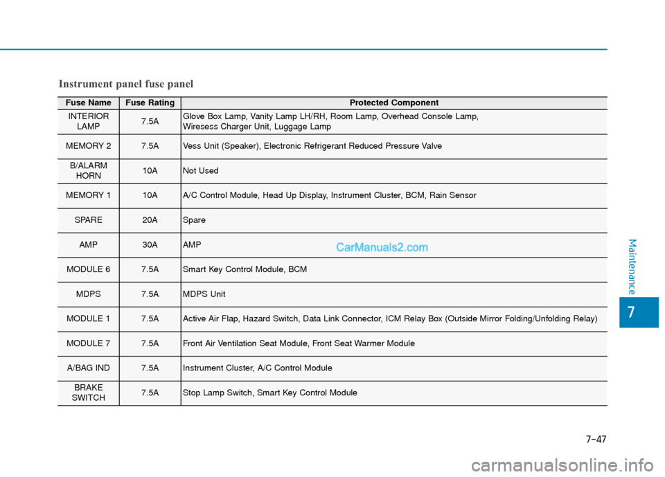
Fuse NameFuse RatingProtected Component
INTERIORLAMP7.5AGlove Box Lamp, Vanity Lamp LH/RH, Room Lamp, Overhead Console Lamp,
Wiresess Charger Unit, Luggage Lamp
MEMORY 27.5AVess Unit (Speaker), Electronic Refrigerant Reduced Pressure Valve
B/ALARMHORN10ANot Used
MEMORY 110AA/C Control Module, Head Up Display, Instrument Cluster, BCM, Rain Sensor
SPARE20ASpare
AMP30AAMP
MODULE 67.5ASmart Key Control Module, BCM
MDPS7.5AMDPS Unit
MODULE 17.5AActive Air Flap, Hazard Switch, Data Link Connector, ICM Relay Box (Outside Mirror Folding/Unfolding Relay)
MODULE 77.5AFront Air Ventilation Seat Module, Front Seat Warmer Module
A/BAG IND7.5AInstrument Cluster, A/C Control Module
BRAKE
SWITCH7.5AStop Lamp Switch, Smart Key Control Module
Instrument panel fuse panel
Page 428 of 540

7-48
Maintenance
Fuse NameFuse RatingProtected Component
START7.5ASmart Key Control Module, EPCU
CLUSTER7.5AHead Up Display, Instrument Cluster
DOOR LOCK20ADoor Lock Relay, Door Unlock Relay, ICM Relay Box (Two Turn Unlock Relay)
PDM 27.5AStart/Stop Button Switch
FCA10AForward Collision Avoidance Assist Unit
S/HEATER20AFront Seat Warmer Module, Front Air Ventilation Seat Module
SPARE20ASpare
A/C7.5AA/C Control Module, Cluster Ionizer
PDM 115ASmart Key Control Module
E-SHIFTER10AShift Select Switch (SBW), Front Console Switch
AIR BAG15ASRS Control Module, Passenger Occupant Detection Sensor
IG125APCB Block(FUSE : IEB 3, EPCU 2)
Instrument panel fuse panel
Page 465 of 540

How to Disconnect Portable Charger .........................H41
Charging Connector Manual Release ..........................H42
Precautions When Using the Portable Charger ........H42
EV Charging Troubleshooting
- Steps to Consider ...............................................H43
How to Start the Vehicle ......................................H44
How to Stop the Vehicle.......................................H44
Virtual Engine Sound System ..............................H45
Distance to Empty .................................................H45
When destination is not set ...........................................H46
Navigation - When a Destination is Set .....................H46
Tips for Improving Range When Using the
Climate Control System ........................................H46
Tips for Improving Range While Driving ............H47
Power/Charge Gauge............................................H47
State of Charge (SOC) Gauge for
High Voltage Battery ...........................................H47
Warning and Indicator Lights .............................H48
Ready Indicator ................................................................H48
Service Warning Light .....................................................H48
Power Down Warning Light ...........................................H49
Charging Indicator Light..................................................H49
High Voltage Battery Level Warning Light .................H49
Regenerative Brake Warning Light ..............................H49
LCD Display Messages ..........................................H50
Shift to P to charge .........................................................H50
Remaining Time .................................................................H50
Unplug vehicle to start ....................................................H50
Charging Door Open ........................................................H51Charging Stopped. Check the AC/DC charger ...........H51
Charging Stopped. Check the cable connection .......H52
Check regenerative brakes/
Stop vehicle and check regenerative brakes ............H52 Low Battery........................................................................\
H52
Charge immediately. Power limited ..............................H53
Low outside temperature may limit power output.
Charge EV battery/Low EV battery temperature.
Power limited .....................................................................H53\
EV Battery Overheated! Stop vehicle..........................H54
Power limited .....................................................................H54\
Stop vehicle and check power supply .........................H55
Check Virtual Engine Sound System............................H55
Check electric vehicle system .......................................H55
Energy Flow ..........................................................H56
Vehicle Stop........................................................................\
H56
EV Propulsion ....................................................................H56
Regeneration ......................................................................H5\
6
Aux. Battery Saver+ .............................................H57
Mode ........................................................................\
............H57
System Setting...................................................................H58
LCD Message .....................................................................H58\
Utility Mode ............................................................H59
System Setting and Activation ......................................H59
System Deactivation .........................................................H59
If an Accident Occurs ...........................................H60
Additional Precautions..........................................H62
Service Interlock Connector ................................H62
Service Plug ...........................................................H62
Page 471 of 540

H8
E
EV
V
M
M O
OD
DE
E
(
( C
C O
O N
NT
T.
.)
)
Energy Information
Select ‘EV →Energy Information’ on
the screen.
You can check battery information
and energy consumption.
Battery information
You can check the vehicle expected
range, total battery power remaining,
and expected charging time for each
charge type.
The displayed range is calculated based on the real time energy effi-
ciency while driving. The displayed
range may change as the driving
pattern or conditions change.
Note that the range may be differ- ent from a given state of charge
(SOC%) depending on drive mode,
drive conditions, and driving pat-
terns.
Energy consumption
You can check the current energy
consumption for each system of the
vehicle.
➀ ‘Driving’ shows the total power and
energy consumption of the electric
motor kW usage when driving and
kW storage when regenerative
braking is applied.
➁ ‘Climate’ shows the power and
energy consumption which are
used by the heater or air condition-
er.
➂ ‘Electronics’ shows the power and
energy consumption which are
used by the vehicle systems
including the cluster, infotainment
system, headlamp, vehicle control
unit, etc.
Page 475 of 540

H12
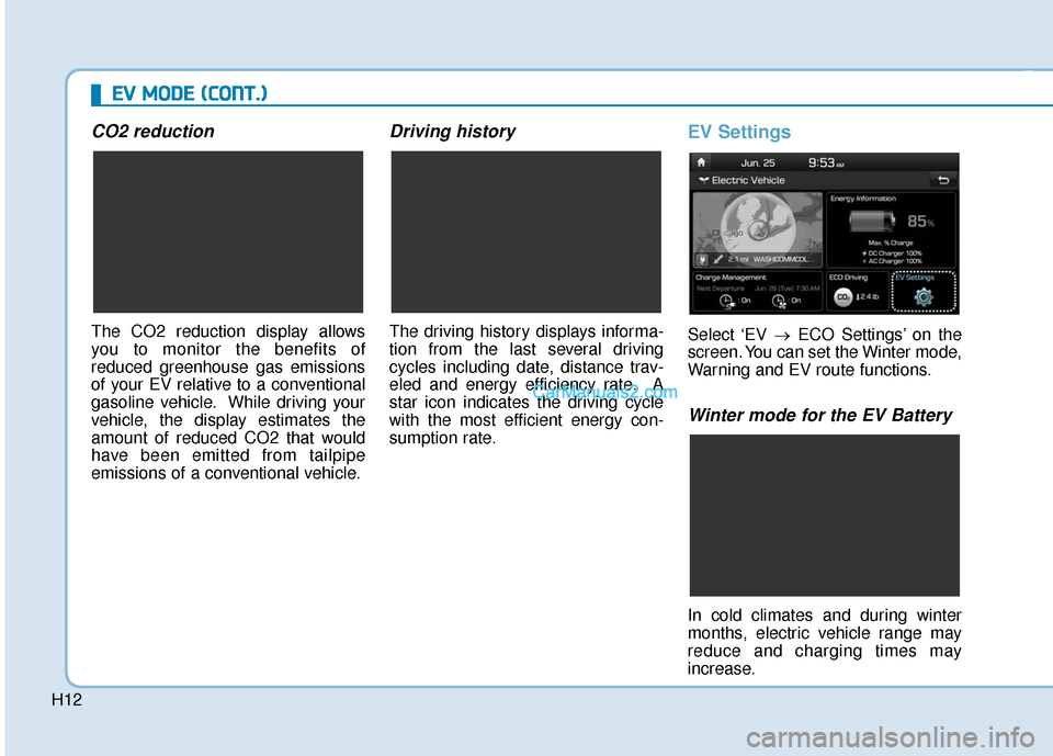
CO2 reduction
The CO2 reduction display allows
you to monitor the benefits of
reduced greenhouse gas emissions
of your EV relative to a conventional
gasoline vehicle. While driving your
vehicle, the display estimates the
amount of reduced CO2 that would
have been emitted from tailpipe
emissions of a conventional vehicle.
Driving history
The driving history displays informa-
tion from the last several driving
cycles including date, distance trav-
eled and energy efficiency rate. A
star icon indicates the driving cycle
with the most efficient energy con-
sumption rate.
EV Settings
Select ‘EV →ECO Settings’ on the
screen. You can set the Winter mode,
Warning and EV route functions.
Winter mode for the EV Battery
In cold climates and during winter
months, electric vehicle range may
reduce and charging times may
increase.
E E V
V
M
M O
OD
DE
E
(
( C
C O
O N
NT
T.
.)
)
Page 476 of 540

H13
This is primarily due to reduced per-
formance of the EV battery when
exposed to cold temperatures.
Some vehicles may come equipped
with Winter mode selectable option.
The Winter mode feature can be
selected in the EV Settings menu.
When selected, Winter mode
enables the use of the EV battery
coolant heater. This mode is recom-
mended to improve EV battery per-
formance in cold climate conditions.
Note that EV range may reduce
when Winter mode is enabled, as
electrical energy is used to maintain
the EV battery temperature.
Winter mode enables operation of
the EV battery coolant heater. While
driving your vehicle, if the battery
temperature is low or the A/C and/or
heater is turned ON, the EV battery
coolant heater will be used.
Note that the EV battery coolant
heater will not be used when the EV
battery SOC is low.
❈This mode is available for the vehi-
cles equipped with the battery
heater.Warning
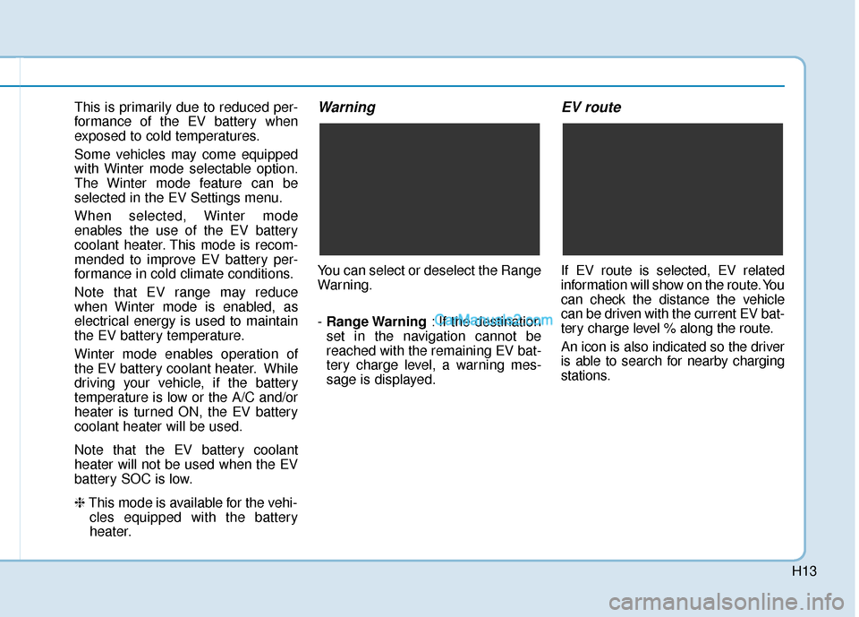
You can select or deselect the Range
Warning.
- Range Warning : If the destination
set in the navigation cannot be
reached with the remaining EV bat-
tery charge level, a warning mes-
sage is displayed.
EV route
If EV route is selected, EV related
information will show on the route. You
can check the distance the vehicle
can be driven with the current EV bat-
tery charge level % along the route.
An icon is also indicated so the driver
is able to search for nearby charging
stations.