Page 442 of 603
6-41
What to do in an emergency
6
When towing your vehicle in an
emergency without wheel dollies :
1. Place the Engine Start/Stop but-ton in the ACC position.
2. Place the shift lever in N (Neutral).
3. Release the parking brake.Removable Towing Hook
1. Open the liftgate, and take the towing hooks out from the tool
case.
2. Remove the hole cover by press-ing the lower part of the cover on
the front or rear bumper.
3. Install the towing hook by turning it clockwise into the hole until it is
fully secured.
4. Remove the towing hook and install the cover after use.
Failure to place the transmis-
sion shift lever in N (Neutral)
may cause internal damage to
the transmission.
CAUTION
OAE066021N
OAE066022N
OAE066028N
■Front
■Rear
Page 443 of 603
6-42
What to do in an emergency
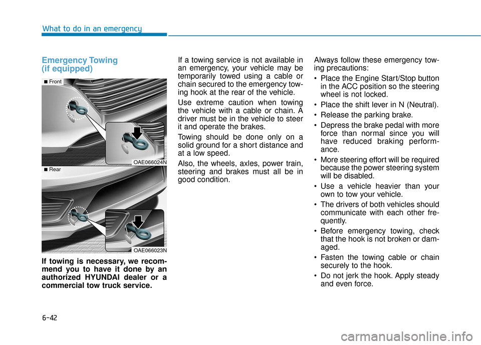
Emergency Towing
(if equipped)
If towing is necessary, we recom-
mend you to have it done by an
authorized HYUNDAI dealer or a
commercial tow truck service.If a towing service is not available in
an emergency, your vehicle may be
temporarily towed using a cable or
chain secured to the emergency tow-
ing hook at the rear of the vehicle.
Use extreme caution when towing
the vehicle with a cable or chain. A
driver must be in the vehicle to steer
it and operate the brakes.
Towing should be done only on a
solid ground for a short distance and
at a low speed.
Also, the wheels, axles, power train,
steering and brakes must all be in
good condition.
Always follow these emergency tow-
ing precautions:
Place the Engine Start/Stop button
in the ACC position so the steering
wheel is not locked.
Place the shift lever in N (Neutral).
Release the parking brake.
Depress the brake pedal with more force than normal since you will
have reduced braking perform-
ance.
More steering effort will be required because the power steering system
will be disabled.
Use a vehicle heavier than your own to tow your vehicle.
The drivers of both vehicles should communicate with each other fre-
quently.
Before emergency towing, check that the hook is not broken or dam-
aged.
Fasten the towing cable or chain securely to the hook.
Do not jerk the hook. Apply steady and even force.
OAE066024N
OAE066023N
■Front
■Rear
Page 462 of 603
7-17
7
Maintenance
Information
Use only the specified engine oil (refer
to "Recommended Lubricants and
Capacities" in chapter 8).
Checking the Engine Oil and
Filter
Have engine oil and filter changed by
an authorized HYUNDAI dealer
according to the Maintenance
Schedule at the beginning of this
chapter.
i
The electric motor for
the cooling fan may
continue to operate
or start up when the
engine is not running
and can cause serious injury.
Keep hands, clothing and tools
away from the rotating fan
blades of the cooling fan.
WARNING
CALIFORNIA PROPOSITION 65
WARNING
Engine oil contains chemicals
known to the State of California
to cause cancer, birth defects
and reproductive harm. Used
engine oil may cause irritation
or cancer of the skin if left in
contact with the skin for pro-
longed periods of time. Always
protect your skin by washing
your hands thoroughly with
soap and warm water as soon
as possible after handling used
oil.
WARNING
Page 477 of 603
When you do not use the vehiclefor a long time in a low tempera-
ture area, disconnect the battery
and keep it indoors.
Always charge the battery fully to prevent battery case damage
in low temperature areas.
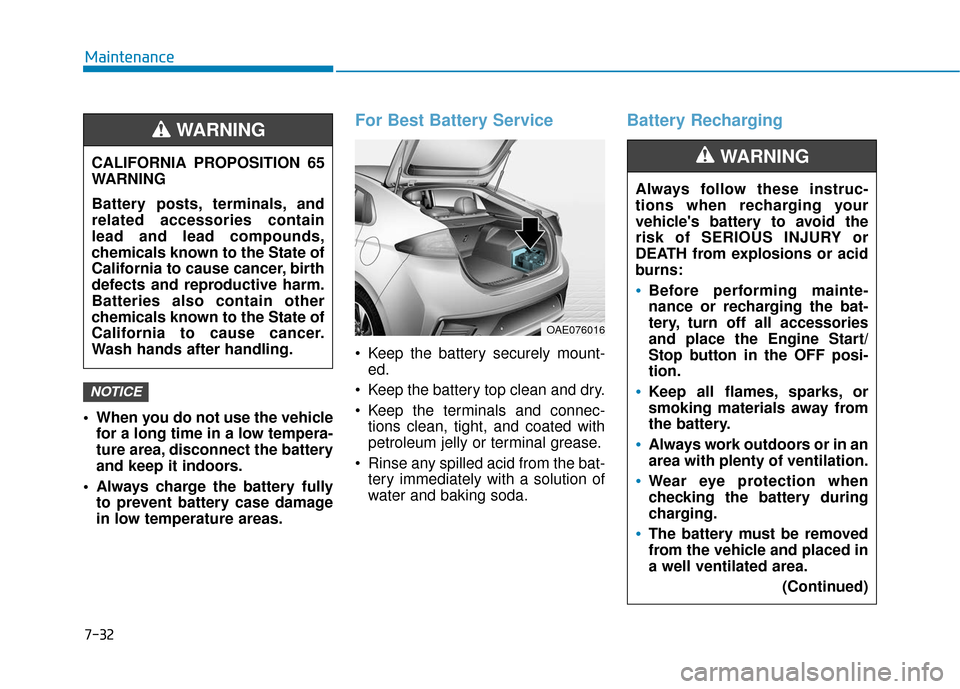
For Best Battery Service
Keep the battery securely mount-ed.
Keep the battery top clean and dry.
Keep the terminals and connec- tions clean, tight, and coated with
petroleum jelly or terminal grease.
Rinse any spilled acid from the bat- tery immediately with a solution of
water and baking soda.
Battery Recharging
NOTICE
7-32
Maintenance
CALIFORNIA PROPOSITION 65
WARNING
Battery posts, terminals, and
related accessories contain
lead and lead compounds,
chemicals known to the State of
California to cause cancer, birth
defects and reproductive harm.
Batteries also contain other
chemicals known to the State of
California to cause cancer.
Wash hands after handling.
WARNING
Always follow these instruc-
tions when recharging your
vehicle's battery to avoid the
risk of SERIOUS INJURY or
DEATH from explosions or acid
burns:
Before performing mainte-
nance or recharging the bat-
tery, turn off all accessories
and place the Engine Start/
Stop button in the OFF posi-
tion.
Keep all flames, sparks, or
smoking materials away from
the battery.
Always work outdoors or in an
area with plenty of ventilation.
Wear eye protection when
checking the battery during
charging.
The battery must be removed
from the vehicle and placed in
a well ventilated area. (Continued)
WARNING
OAE076016
Page 478 of 603
By jump starting
After a jump start from a good bat-
tery, drive the vehicle for 20-30 min-
utes before it is shutoff. The vehicle
may not restart if you shut it off
before the battery had a chance to
adequately recharge. See "Jump
Starting" in chapter 6 for more infor-
mation on jump starting procedures.
Information
An inappropriately disposedbattery can be harmful to
the environment and human
health. Dispose of the bat-
tery according to your local
law(s) or regulations.
Reset Features
The following items may need to be
reset after the battery has been dis-
charged or the battery has been dis-
connected. See chapter 3 or 4 for:
Power Windows
Trip Computer
Climate Control System
Clock
Audio System
Sunroof
Driver Position Memory System
i
7-33
7
Maintenance
(Continued)
Watch the battery during
charging, and stop or reduce
the charging rate if the battery
cells begin boiling violently.
The negative battery cable
must be removed first and
installed last when the battery
is disconnected. Disconnect
the battery charger in the fol-
lowing order:
(1) Turn off the battery charg- er main switch.
(2) Unhook the negative
clamp from the negative
battery terminal.
(3) Unhook the positive clamp from the positive battery
terminal.
Always use a genuine
HYUNDAI approved battery
when you replace the battery.
Page 490 of 603
7-45
7
Maintenance
Kilopascal (kPa)
The metric unit for air pressure.
Light truck(LT) tire
A tire designated by its manufacturer
as primarily intended for use on light-
weight trucks or multipurpose pas-
senger vehicles.
Load ratings
The maximum load that a tire is rated
to carry for a given inflation pressure.
Load Index
An assigned number ranging from 1
to 279 that corresponds to the load
carrying capacity of a tire.
Maximum Inflation Pressure
The maximum air pressure to which
a cold tire may be inflated. The max-
imum air pressure is molded onto the
sidewall.
Maximum Load Rating
The load rating for a tire at the maxi-
mum permissible inflation pressure
for that tire.
Maximum Loaded VehicleWeight
The sum of curb weight; accessory
weight; vehicle capacity weight; and
production options weight.
Normal Occupant Weight
The number of occupants a vehicle
is designed to seat multiplied by 150
pounds (68 kg).
Occupant Distribution
Designated seating positions.
Outward Facing Sidewall
An asymmetrical tire has a particular
side that faces outward when mount-
ed on a vehicle. The outward facing
sidewall bears white lettering or
bears manufacturer, brand, and/or
model name molding that is higher or
deeper than the same moldings on
the inner facing sidewall.
Passenger (P-Metric) tire
A tire used on passenger cars and
some light duty trucks and multipur-
pose vehicles.
Ply
A layer of rubber-coated parallel
cords.
Pneumatic tire
A mechanical device made of rubber,
chemicals, fabric and steel or other
materials, that, when mounted on an
automotive wheel provides the trac-
tion and contains the gas or fluid that
sustains the load.
Pneumatic options weight
The combined weight of installed
regular production options weighing
over 5 lb. (2.3 kg) in excess of the
standard items which they replace,
not previously considered in curb
weight or accessory weight, includ-
ing heavy duty breaks, ride levelers,
roof rack, heavy duty battery, and
special trim.
Page 491 of 603
7-46
Maintenance
Recommended InflationPressure
Vehicle manufacturer's recommend-
ed tire inflation pressure as shown
on the tire placard.
Radial Ply Tire
A pneumatic tire in which the ply
cords that extend to the beads are
laid at 90 degrees to the centerline of
the tread.
Rim
A metal support for a tire and upon
which the tire beads are seated.
Sidewall
The portion of a tire between the
tread and the bead.
Speed Rating
An alphanumeric code assigned to a
tire indicating the maximum speed at
which a tire can operate.
Traction
The friction between the tire and the
road surface. The amount of grip pro-
vided.
Tread
The portion of a tire that comes into
contact with the road.
Treadwear Indicators
Narrow bands, sometimes called
"wear bars", that show across the
tread of a tire when only 1/16 inch of
tread remains.
UTQGS
Uniform Tire Quality Grading
Standards is a tire information sys-
tem that provides consumers with
ratings for a tire's traction, tempera-
ture and treadwear. Ratings are
determined by tire manufacturers
using government testing proce-
dures. The ratings are molded into
the sidewall of the tire.
Vehicle Capacity Weight
The number of designated seating
positions multiplied by 150 lbs. (68
kg) plus the rated cargo and luggage
load.
Vehicle Maximum Load on theTire
Load on an individual tire due to curb
and accessory weight plus maximum
occupant and cargo weight.
Vehicle Normal Load on the Tire
Load on an individual tire that is
determined by distributing to each
axle its share of the curb weight,
accessory weight, and normal occu-
pant weight and dividing by 2.
Vehicle Placard
A label permanently attached to a
vehicle showing the original equip-
ment tire size and recommended
inflation pressure.
Page 547 of 603
H12
Information
• Even though charging is possiblewith the Engine Start/Stop button in
the ON/START position, for your
safety, start charging when the
Engine Start/Stop button is in the
OFF position and the vehicle shifted
to P (Park). After charging has
started, you can use electrical com-
ponents such as the radio by press-
ing the Engine Start/Stop button to
the ACC or ON position.
• During normal charging, the radio reception may be bad.
• Moving the shift lever from P (Park) to R (Reverse)/N (Neutral)/D
(Drive) stops the charging process.
To restart the charging process,
move the shift lever to P (Park),
place the Engine Start/Stop button
to the OFF position, and disconnect
the charging cable. Then, connect
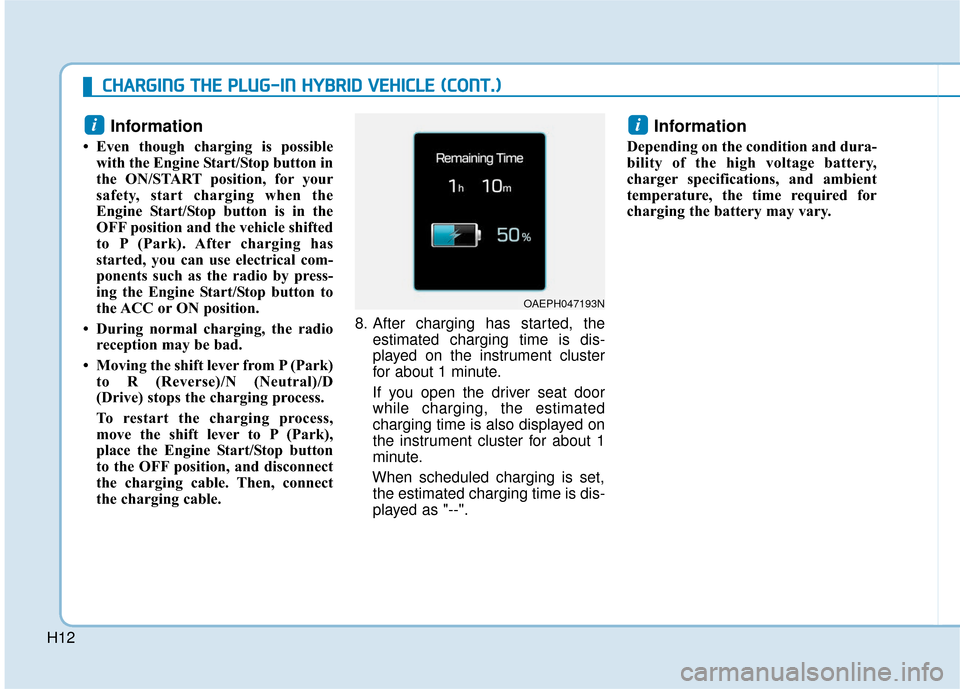
the charging cable. 8. After charging has started, the
estimated charging time is dis-
played on the instrument cluster
for about 1 minute.
If you open the driver seat door
while charging, the estimated
charging time is also displayed on
the instrument cluster for about 1
minute.
When scheduled charging is set, the estimated charging time is dis-
played as "--".
Information
Depending on the condition and dura-
bility of the high voltage battery,
charger specifications, and ambient
temperature, the time required for
charging the battery may vary.
ii
OAEPH047193N
C
C H
H A
AR
RG
G I
IN
N G
G
T
T H
H E
E
P
P L
LU
U G
G-
-I
IN
N
H
H Y
Y B
BR
RI
ID
D
V
V E
EH
H I
IC
C L
LE
E
(
( C
C O
O N
NT
T.
.)
)