Page 163 of 526

3-16
Convenient features of your vehicle
Electric power steering (EPS)
The system assists you with steering
the vehicle. If the vehicle is off or if
the power steering system becomes
inoperative, the vehicle may still be
steered, but it will require increased
steering effort.
Also, the steering effort becomes
heavier as the vehicle’s speed
increases and becomes lighter as
the vehicle’s speed decreases for
better control of the steering wheel.
Should you notice any change in the
effort required to steer during normal
vehicle operation, we recommend
that the system be checked by a
HYUNDAI authorised repairer.
If the Electric Power SteeringSystem does not operate nor-
mally, the warning light ( ) will
illuminate or blink on the instru-
ment cluster. The steering wheel
may become difficult to control
or operate. We recommend that
you take your vehicle to a
HYUNDAI authorised repairer
and have the system checked as
soon as possible.
(Continued)(Continued)
When abnormality is detected in
the electric power steering sys-
tem, to prevent a deadly acci-
dent, the steering assist function
will stop. At this time, the warn-
ing light turns on or blinks on
the cluster. The steering wheel
may become difficult to control
or operate. Have your vehicle
checked immediately, after mov-
ing the vehicle to a safe zone.
Information
The following symptoms may occur
during normal vehicle operation:
• The steering effort may be highimmediately after placing the
POWER button in the ON position.
This happens as the system per-
forms the EPS system diagnostics.
When the diagnostics is completed,
the steering wheel will return to its
normal condition.
(Continued)(Continued)
• A click noise may be heard from the
EPS relay after the POWER button
is in the ON or OFF position.
• Motor noise may be heard when the vehicle is at a stop or at a low driv-
ing speed.
• When you operate the steering wheel in low temperature, abnormal
noise may occur. If temperature
rises, the noise will disappear. This
is a normal condition.
• When the vehicle is stationary, if you turn the steering wheel all the
way to the left or right continuously,
the steering wheel effort increases.
This is not a system malfunction. As
time passes, the steering wheel
effort will return to its normal con-
dition.
i
NOTICE
S
ST
T E
EE
ER
R I
IN
N G
G
W
W H
HE
EE
EL
L
Page 450 of 526

Tyres and wheels .................................................7-23
Tyre care ........................................................................\
...7-23
Recommended cold tyre inflation pressures ...........7-24
Check tyre inflation pressure ......................................7-25
Tyre rotation ....................................................................7-26\
Wheel alignment and tyre balance.............................7-27
Tyre replacement ............................................................7-27
Wheel replacement .........................................................7-28
Tyre traction .....................................................................7-2\
8
Tyre maintenance ...........................................................7-28
Tyre sidewall labeling ................................................... 7-28
Low aspect ratio tyres...................................................7-32
Fuses ......................................................................7-\
34
Instrument panel fuse replacement ...........................7-35
Motor compartment panel fuse replacement ..........7-36
Fuse/relay panel description .......................................7-37
Light bulbs.............................................................7-49
Headlamp, position lamp, turn signal lamp
bulb replacement .............................................................7-50
Headlamp aiming .............................................................7-54
Daytime running lamp ....................................................7-57
Side repeater lamp replacement .................................7-57
Rear combination lamp bulb replacement ................7-57
Rear fog lamp ..................................................................7-60
High mounted stop lamp ...............................................7-60
License plate light bulb replacement .........................7-60
Interior light bulb replacement ....................................7-60
Appearance care ..................................................7-62
Exterior care ....................................................................7-62\
Interior care......................................................................7-\
67
Page 485 of 526

7-37
7
Maintenance
4. Check the removed fuse; replace itif it is blown. To remove or insert
the fuse, use the fuse puller in the
motor compartment fuse panel.
5. Push in a new fuse of the same rating, and make sure it fits tightly
in the clips. If it fits loosely, consult
a HYUNDAI authorised repairer.
After checking the fuse panel in
the motor compartment, securely
install the fuse panel cover. You
may hear a clicking sound if the
cover is securely latched. If it is
not securely latched, electrical
failure may occur from water con-
tact.Multi fuse
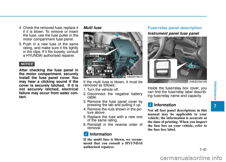
If the multi fuse is blown, it must be
removed as follows:
1. Turn the vehicle off.
2. Disconnect the negative battery cable.
3. Remove the fuse panel cover by pressing the tab and pulling it up.
4. Remove the nuts shown in the pic- ture above.
5. Replace the fuse with a new one of the same rating.
6. Reinstall in the reverse order of removal.
Information
If the multi fuse is blown, we recom-
mend that you consult a HYUNDAI
authorised repairer.
Fuse/relay panel description
Instrument panel fuse panel
Inside the fuse/relay box cover, you
can find the fuse/relay label describ-
ing fuse/relay name and capacity.
Information
Not all fuse panel descriptions in this
manual may be applicable to your
vehicle; the information is accurate at
the time of printing. When you inspect
the fuse box on your vehicle, refer to
the fuse box label.
i
i
NOTICE
OAEE076013
OAEE076014R
Page 488 of 526

7-40
Maintenance
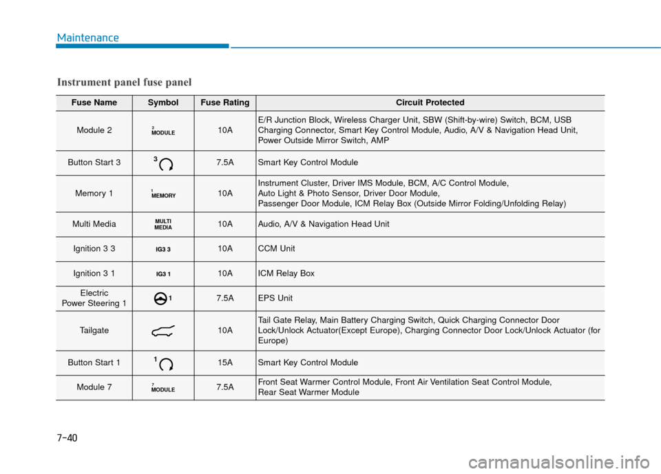
Fuse NameSymbolFuse RatingCircuit Protected
Module 2MODULE210AE/R Junction Block, Wireless Charger Unit, SBW (Shift-by-wire) Switch, BCM, USB
Charging Connector, Smart Key Control Module, Audio, A/V & Navigation Head Unit,
Power Outside Mirror Switch, AMP
Button Start 337.5ASmart Key Control Module
Memory 1MEMORY110AInstrument Cluster, Driver IMS Module, BCM, A/C Control Module,
Auto Light & Photo Sensor, Driver Door Module,
Passenger Door Module, ICM Relay Box (Outside Mirror Folding/Unfolding Relay)
Multi MediaMULTI
MEDIA10AAudio, A/V & Navigation Head Unit
Ignition 3 3 10ACCM Unit
Ignition 3 1 10AICM Relay Box
Electric
Power Steering 117.5AEPS Unit
Tailgate10ATail Gate Relay, Main Battery Charging Switch, Quick Charging Connector Door
Lock/Unlock Actuator(Except Europe), Charging Connector Door Lock/Unlock Actuator (for
Europe)
Button Start 1115ASmart Key Control Module
Module 7MODULE77.5AFront Seat Warmer Control Module, Front Air Ventilation Seat Control Module,
Rear Seat Warmer Module
Instrument panel fuse panel
Page 489 of 526
7-41
7
Maintenance
Fuse NameSymbolFuse RatingCircuit Protected
Heated Steering15ABCM
Sunroof20ASunroof Motor
Power WindowRight-handRH25APower Window (RH) Relay, Passenger Power Window Switch, Driver Safety Power Window
Power Window Left-handLH25APower Window (LH) Relay, Driver Power Window Switch,
Passenger Safety Power Window Module
Button Start 227.5AImmobiliser Module, Smart Key Control Module, Start/Stop Button Switch
Brake SwitchBRAKE
SWITCH7.5AStop Lamp Switch, Smart Key Control Module
OBC10AOBC
Air conditioner7.5AIonizer, A/C Control Module, Electronic A/C Compressor, E/R Junction Block
Washer15AMultifunction Switch
Seat Heater RearRR25ARear Seat Warmer Module
Charger10ACCM Unit(for Europe), Normal Charging Connector Lamp(except Europe),
ICM Relay Box (Charging Connector Lock/Unlock Relay)
Power Seat DriverDRV30ADriver Seat Manual Switch, Driver IMS Module
Instrument panel fuse panel
Page 490 of 526
7-42
Maintenance
Fuse NameSymbolFuse RatingCircuit Protected
AMP30AAMP
Module 1MODULE110ADriver Power Outside Mirror, Passenger Power Outside Mirror, Data Link Connector,
FCA Unit
Door Lock20ADoor Lock/Unlock Relay, ICM Relay Box (Dead Lock Relay),
Driver/Passenger Smart Key Outside Handle, Driver/Passenger Door Module
Wiper Front 2FRT210AWiper Motor, PCB Block (Front Wiper (Low) Relay)
Module 6MODULE67.5ABCM, Smart Key Control Module
Seat Heater FrontFRT25AFront Seat Warmer Control Module, Front Air Ventilation Seat Control Module
Heated Mirror10ADriver Power Outside Mirror, Passenger Power Outside Mirror, A/C Control Module
Rear Heated25ARear Defogger (+) (Upper)
Wiper Front 1FRT130AWiper Motor, PCB Block (Front Wiper (Low) Relay)
Instrument panel fuse panel
Page 491 of 526
7-43
7
Maintenance
Motor compartment fuse panel
Inside the fuse/relay box cover, you
can find the fuse/relay label describ-
ing fuse/relay name and capacity.
Information
Not all fuse panel descriptions in this
manual may be applicable to your
vehicle; the information is accurate at
the time of printing. When you inspect
the fuse panel in your vehicle, refer to
the fuse panel label.
i
OAEE076016
OAEE076048L
Page 494 of 526
7-46
Maintenance
TypeSymbolFuse RatingCircuit Protected
Fuse
10ASCU, SBW Switch, Front Console Switch
10AEngine Room Junction Block, Electronic A/C Compressor
10AElectric Water Pump (EV)
15AICM Relay Box
15AActive Air Flap, E/R Junction Block
15ABMS Control Module
10ABurglar Alarm Horn Relay
10AEPCU
10AMultipurpose Check Connector, IBAU
10AEPCU, OBC, VPD Relay, BMS Control Module
Motor compartment fuse panel