Page 338 of 526

5-22
Driving your vehicle
Information
• For your safety, you can engage theEPB even though the POWER but-
ton is in the OFF position, but you
cannot release it.
• For your safety, depress the brake pedal and release the parking brake
manually with the EPB switch when
you drive downhill or when backing
up the vehicle.
If the parking brake warning light is still on even though the EPB
has been released, we recom-
mend that the system be
checked a HYUNDAI authorised
repairer.
Do not drive your vehicle with the EPB applied. It may cause
excessive brake pad and brake
rotor wear.
Electronic Parking Brake) may be
automatically applied when:
Requested by other systems
The vehicle is turned off with theEPB applied
Information
If the driver turns the vehicle off
whilst Auto Hold is operating, EPB
will be automatically applied.
However, if you press the EPB switch
within one second after the vehicle is
turned off, the EPB will not be
applied.
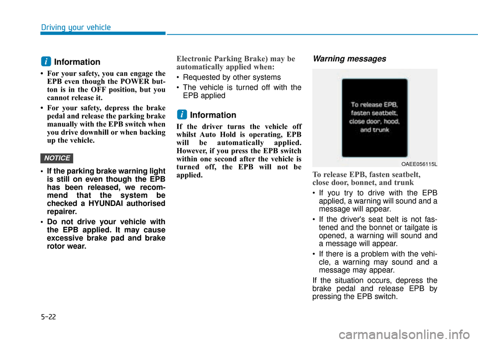
Warning messages
To release EPB, fasten seatbelt,
close door, bonnet, and trunk
If you try to drive with the EPBapplied, a warning will sound and a
message will appear.
If the driver's seat belt is not fas- tened and the bonnet or tailgate is
opened, a warning will sound and
a message will appear.
If there is a problem with the vehi- cle, a warning may sound and a
message may appear.
If the situation occurs, depress the
brake pedal and release EPB by
pressing the EPB switch.
i
NOTICE
i
OAEE056115L
Page 345 of 526
![Hyundai Ioniq Electric 2019 Owners Manual - RHD (UK, Australia) 5-29
Driving your vehicle
5
Press brake pedal to deactivate
AUTO HOLD
If you did not apply the brake pedal
when you release the Auto Hold by
pressing the [AUTO HOLD] switch, a
warning will sound and a Hyundai Ioniq Electric 2019 Owners Manual - RHD (UK, Australia) 5-29
Driving your vehicle
5
Press brake pedal to deactivate
AUTO HOLD
If you did not apply the brake pedal
when you release the Auto Hold by
pressing the [AUTO HOLD] switch, a
warning will sound and a](/manual-img/35/14899/w960_14899-344.png)
5-29
Driving your vehicle
5
Press brake pedal to deactivate
AUTO HOLD
If you did not apply the brake pedal
when you release the Auto Hold by
pressing the [AUTO HOLD] switch, a
warning will sound and a message
will appear.
AUTO HOLD conditions not met.
Close door, hood, trunk, and fasten
seatbelt
When you press the [AUTO HOLD]
switch, if the driver’s door, bonnet
and tailgate are not closed or the dri-
ver’s seat belt is unfastened, a warn-
ing will sound and a message will
appear on the LCD display.
Press the [AUTO HOLD] switch after
closing the driver’s door, bonnet and
tailgate and fastening the seat belt.
Anti-lock Brake System (ABS)
OAEE056116LOAEE056118L
An Anti-Lock Braking System
(ABS) or an Electronic Stability
Control (ESC) system will not
prevent accidents due to
improper or dangerous driving
manoeuvres. Even though vehi-
cle control is improved during
emergency braking, always
maintain a safe distance
between you and objects ahead
of you. Vehicle speeds should
always be reduced during
extreme road conditions. The
braking distance for cars
equipped with ABS or ESC may
be longer than for those without
these systems in the following
road conditions.
Drive your vehicle at reduced
speeds during the following
conditions:
Rough, gravel or snow-cov-
ered roads.(Continued)
WARNING
Page 446 of 526
6-23
What to do in an emergency
6
When towing your vehicle in an
emergency without wheel dollies:
1. Whilst depressing the brake pedalshift to the N (Neutral) position
and turn the vehicle off. The
POWER button will be in the ACC
position.
2. Release the parking brake.
Failure to shift to N (Neutral) may
cause internal damage to the vehi-
cle.Removable towing hook
1. Open the tailgate and remove the towing hook from the tool case.
The tool case is placed under the
luggage tray.
2. Remove the hole cover by press-ing the lower part of the cover on
the bumper.
3. Install the towing hook by turning it clockwise into the hole until it is
fully secured.
4. Remove the towing hook and install the cover after use.
NOTICE
OAEE066010
OAEE066011
OAE066028
■Front
■Rear
Page 488 of 526

7-40
Maintenance
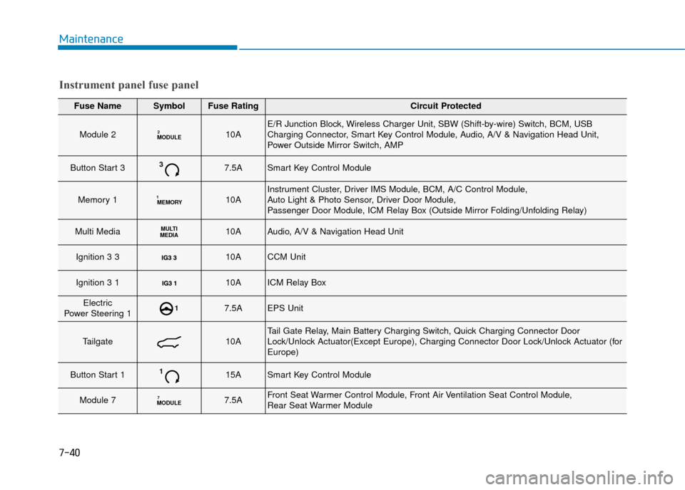
Fuse NameSymbolFuse RatingCircuit Protected
Module 2MODULE210AE/R Junction Block, Wireless Charger Unit, SBW (Shift-by-wire) Switch, BCM, USB
Charging Connector, Smart Key Control Module, Audio, A/V & Navigation Head Unit,
Power Outside Mirror Switch, AMP
Button Start 337.5ASmart Key Control Module
Memory 1MEMORY110AInstrument Cluster, Driver IMS Module, BCM, A/C Control Module,
Auto Light & Photo Sensor, Driver Door Module,
Passenger Door Module, ICM Relay Box (Outside Mirror Folding/Unfolding Relay)
Multi MediaMULTI
MEDIA10AAudio, A/V & Navigation Head Unit
Ignition 3 3 10ACCM Unit
Ignition 3 1 10AICM Relay Box
Electric
Power Steering 117.5AEPS Unit
Tailgate10ATail Gate Relay, Main Battery Charging Switch, Quick Charging Connector Door
Lock/Unlock Actuator(Except Europe), Charging Connector Door Lock/Unlock Actuator (for
Europe)
Button Start 1115ASmart Key Control Module
Module 7MODULE77.5AFront Seat Warmer Control Module, Front Air Ventilation Seat Control Module,
Rear Seat Warmer Module
Instrument panel fuse panel
Page 506 of 526
7-58
Maintenance
Turn signal lamp
1. Turn off the vehicle.
2. Open the tailgate.
3. Open the lamp assembly retainingscrew covers.
4. Loosen the lamp assembly retain- ing screws with a cross-tip screw-
driver. 5. Remove the rear combination
lamp assembly from the body of
the vehicle. 6. Remove the socket from the
assembly by turning the socket
counterclockwise until the tabs on
the socket align with the slots on the
assembly.
7. Remove the bulb from the socket by pressing it in and rotating it counter-
clockwise until the tabs on the bulb
align with the slots in the socket.
Pull the bulb out of the socket.
8. Insert a new bulb by inserting it into the socket and rotating it until it
locks into place.
OAE076038OAE076037OAE076040
Turn signal lamp
Page 507 of 526
7-59
7
Maintenance
9. Install the socket into the assemblyby aligning the tabs on the socket
with the slots in the assembly. Push
the socket into the assembly and
turn the socket clockwise.
10. Reinstall the lamp assembly to the body of the vehicle
Backup lamp
1. Turn off the vehicle.
2. Open the tailgate.
3. Remove the service cover using aflat-blade screwdriver. 4. Remove the socket from the
assembly by turning the socket
counterclockwise until the tabs on
the socket align with the slots on
the assembly.
5. Remove the bulb by pulling it straight out.
6. Insert a new bulb by inserting it into the socket and rotating it until
it locks into place.
7. Install the socket into the assembly by aligning the tabs on the socket
with the slots in the assembly.
Push the socket into the assembly
and turn the socket clockwise.
8. Reinstall the service cover.
OAEE076038
Backup lamp
OAEE076025
Page:
< prev 1-8 9-16 17-24