Page 555 of 659

7-42
Maintenance
A
A I
I R
R
C
C L
L E
E A
A N
N E
E R
R
F
F U
U E
E L
L
F
F I
I L
L T
T E
E R
R
(
( F
F O
O R
R
D
D I
I E
E S
S E
E L
L )
)
Draining water from fuel filter
The fuel filter in the diesel engine
operates the critical function of sepa-
rating water from the fuels and accu-
mulating the water in its bottom.
When enough water is accumulated
inside the fuel filter, the warning light
( ) illuminates with the ignition
switch in the ON position.
In this case, we recommend you to
have the system checked by an
authorized HYUNDAI dealer.
When the accumulated water is not
drained at a proper timing, water
may permeate in the fuel filter,
damaging the major vehicle com-
ponents, such as the fuel system.
Fuel filter cartridge replace-
ment
We recommend the fuel filter car-
tridge be replaced by an authorized
HYUNDAI dealer according to the
Maintenance Schedule at the begin-
ning of this chapter.
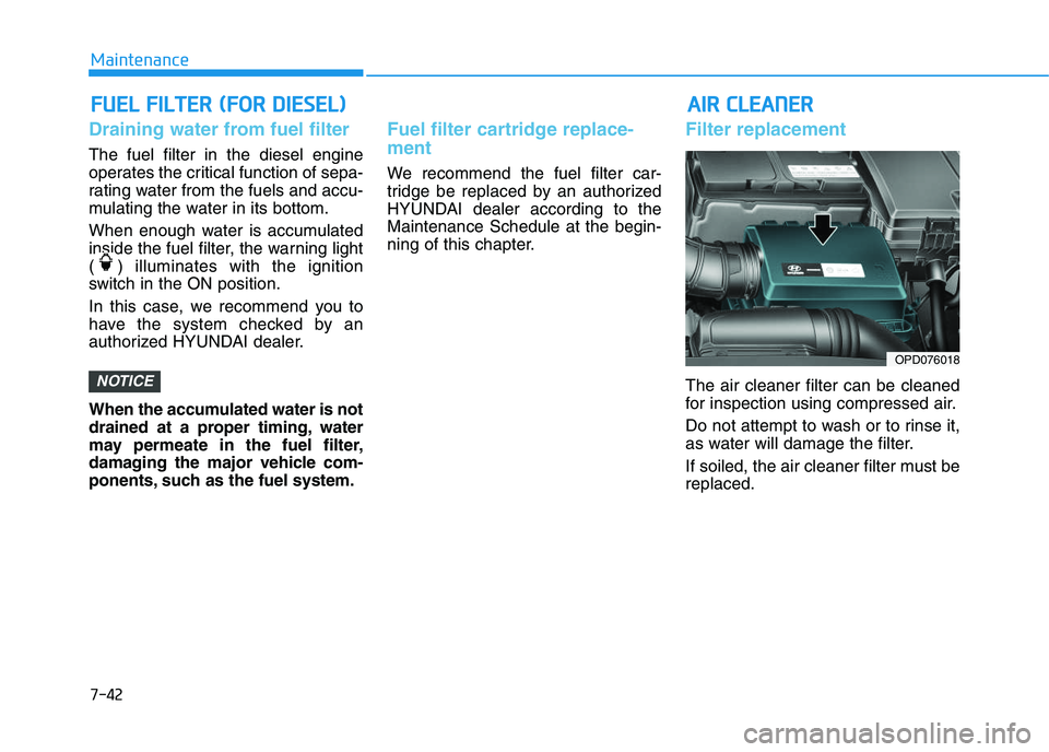
Filter replacement
The air cleaner filter can be cleaned
for inspection using compressed air.
Do not attempt to wash or to rinse it,
as water will damage the filter.
If soiled, the air cleaner filter must be
replaced.NOTICE
OPD076018
Page 565 of 659

7-52
Maintenance
T
T I
I R
R E
E S
S
A
A N
N D
D
W
W H
H E
E E
E L
L S
S
Tire care
For proper maintenance, safety, and
maximum fuel economy, you must
always maintain recommended tire
inflation pressures and stay within the
load limits and weight distribution rec-
ommended for your vehicle.
All specifications (sizes and pressures)
can be found on a label attached to the
driver’s side center pillar.
(Continued)Replace tires that are worn,
show uneven wear, or are dam-
aged. Worn tires can cause
loss of braking effectiveness,
steering) control, or traction.
ALWAYS replace tires with the
same size as each tire that
was originally supplied with
this vehicle. Using tires and
wheels other than the recom-
mended sizes could cause
unusual handling characteris-
tics, poor vehicle control, or
negatively affect your vehi-
cle’s Anti-Lock Brake System
(ABS) resulting in a serious
accident.
Tire failure may cause loss of
vehicle control resulting in an
accident. To reduce risk of
SERIOUS INJURY or DEATH,
take the following precautions:
Inspect your tires monthly for
proper inflation as well as
wear and damage.
The recommended cold tire
pressure for your vehicle can
be found in this manual and on
the tire label located on the dri-
ver’s side center pillar. Always
use a tire pressure gauge to
measure tire pressure. Tires
with too much or too little
pressure wear unevenly caus-
ing poor handling.
Check the pressure of the
spare every time you check
the pressure of the other tires
on your vehicle.
(Continued)
WARNING
OPD086007
Page 566 of 659

7-53
7
Maintenance
Recommended cold tire infla-
tion pressures
All tire pressures (including the
spare) should be checked when the
tires are cold. “Cold tires” means the
vehicle has not been driven for at
least three hours or driven less than
1.6 km (one mile).
Warm tires normally exceed recom-
mended cold tire pressures by 28 to
41 kPa (4 to 6 psi). Do not release air
from warm tires to adjust the pres-
sure or the tires will be under-inflat-
ed. For recommended inflation pres-
sure, refer to “Tire and Wheels” in
chapter 8.Recommended pressures must
be maintained for the best ride,
vehicle handling, and minimum
tire wear.
Over-inflation or under-inflation
can reduce tire life, adversely
affect vehicle handling, and
lead to sudden tire failure that
could result in loss of vehicle
control resulting in an accident.
Severe under-inflation can lead
to severe heat build-up, causing
blowouts, tread separation and
other tire failures that can result
in the loss of vehicle control
resulting in an accident. This
risk is much higher on hot days
and when driving for long peri-
ods at high speeds.
WARNING
Under-inflation results in
excessive wear, poor handling
and reduced fuel economy.
Wheel deformation is also
possible. Keep your tire pres-
sures at the proper levels. If a
tire frequently needs refilling,
we recommend it be checked
by an authorized HYUNDAI
dealer.
Over-inflation produces a
harsh ride, excessive wear at
the center of the tire tread,
and a greater possibility of
damage from road hazards.
CAUTION
Page 585 of 659
7-72
Maintenance
Engine compartment fuse panel
Relay No.SymbolRelay Name
R LY. 1
3COOLING FAN 3 Relay (Gasoline)
PTC
HEATER2PTC HEATER #2 Relay (Diesel)
R LY. 22COOLING FAN 2 Relay
R LY. 3(IG1)3PDM #3 (IG1) Relay
R LY. 41START Relay
R LY. 5FUEL HEATER Relay (Diesel)
R LY. 6(IG2)4PDM #4 (IG2) Relay
R LY. 7FUEL
PUMPFUEL PUMP Relay
R LY. 8(ACC)2PDM #2 (ACC) Relay
Relay No.SymbolRelay Name
R LY. 91COOLING FAN 1 Relay
R LY. 1 0BLOWER Relay
R LY. 1 1PTC
HEATER1PTC HEATER #1 Relay
R LY. 1 2REAR HEATED Relay
R LY. 1 3PTC
HEATER3PTC HEATER #3 Relay (Diesel)
R LY. 1 4POWER
OUTLETPOWER OUTLET Relay
Page 587 of 659
7-74
Maintenance
Engine compartment fuse panel
Fuse No.Fuse NameSymbolFuse RatingCircuit Protected
F11IGNITION 2IG240AIgnition Switch, E/R Junction Block (RLY.6)
F12GLOW80AGlow Plug Unit
F13PTC
HEATER 1PTC
HEATER150ARLY.11
F14PTC
HEATER 2PTC
HEATER250AR LY. 1
F15PTC
HEATER 3PTC
HEATER350ARLY.13
F16FUEL
HEATER30AR LY. 5
F17POWER
OUTLET 3POWER
OUTLET320ARear Power Outlet 1
F18POWER
OUTLET 2POWER
OUTLET220AFront Power Outlet
F20TCU1T115ATCM
F21VACUUM
PUMPVACUUM PUMP20AVacuum Pump
F22FUEL PUMPFUEL
PUMP20AR LY. 7
Page 595 of 659
7-82
Maintenance
Fuse No.Fuse NameSymbolFuse RatingCircuit Protected
F37SENSOR 2S210AOil Level Sensor , Electronic VGT Actuator, EGR Cooling Valve,
Fuel Pressure Regulating Valve, PM Sensor, Stop Lamp Switch, A/Con Relay,
E/R Junction Block (RLY.2/5/11)
F38ECU 2E210A-
F39ECU 1E120AECM
F40INJECTORINJECTOR15A-
F41SENSOR 1S115ALambda Sensor #1/#2
F42IGNITION
COILIGN
COIL20AIgnition Coil #1/#2/#3/#4
F43ECU 3E 315AECM
F44A/CON10A-
F45ECU 5E510AECM
F46SENSOR 4S415AFuel Filter Heater & Fuel Filter Warning Sensor, Glow Plug Unit
■ U-II 1.6 TCI
Engine compartment fuse panel
Page 620 of 659

7-107
7
Maintenance
Bright-metal maintenance
To remove road tar and insects,use a tar remover, not a scraper or
other sharp object.
To protect the surfaces of bright- metal parts from corrosion, apply a
coating of wax or chrome preser-
vative and rub to a high luster.
During winter weather or in coastal areas, cover the bright metal parts
with a heavier coating of wax or
preservative. If necessary, coat the
parts with non-corrosive petroleum
jelly or other protective compound.
Underbody maintenance
Corrosive materials used for ice and
snow removal and dust control may
collect on the underbody. If these
materials are not removed, acceler-
ated rusting can occur on underbody
parts such as the fuel lines, frame,
floor pan and exhaust system, even
though they have been treated with
rust protection. Thoroughly flush the vehicle under-
body and wheel openings with luke-
warm or cold water once a month,
after off-road driving and at the end of
each winter. Pay special attention to
these areas because it is difficult to
see all the mud and dirt. It will do
more harm than good to wet down the
road grime without removing it. The
lower edges of doors, rocker panels,
and frame members have drain holes
that should not be allowed to clog with
dirt; trapped water in these areas can
cause rusting.
Aluminum wheel maintenance
The aluminum wheels are coated with
a clear protective finish.
Do not use any abrasive cleaner,
polishing compound, solvent,
or wire brushes on aluminum
wheels.
Clean the wheel when it has cooled.
Use only a mild soap or neutral detergent, and rinse thoroughly
with water. Also, be sure to clean
the wheels after driving on salted
roads.
Do not wash the wheels with high- speed car wash brushes.
Do not use any cleanser contain- ing acid or alkaline detergents.
NOTICE
After washing the vehicle, test
the brakes while driving slowly
to see if they have been affected
by water. If braking performance
is impaired, dry the brakes by
applying them lightly while main-
taining a slow forward speed.
WARNING
Page 624 of 659

7-111
7
Maintenance
E
E M
M I
I S
S S
S I
I O
O N
N
C
C O
O N
N T
T R
R O
O L
L
S
S Y
Y S
S T
T E
E M
M
The emission control system of your
vehicle is covered by a written limited
warranty. Please see the warranty
information contained in the Service
Passport in your vehicle.
Your vehicle is equipped with an
emission control system to meet all
emission regulations.
There are three emission control
systems which are as follows.
(1) Crankcase emission control sys-
tem
(2) Evaporative emission control sys- tem
(3) Exhaust emission control system
In order to assure the proper function
of the emission control systems, it is
recommended that you have your car
inspected and maintained by an
authorized HYUNDAI dealer in accor-
dance with the maintenance schedule
in this manual.1. Crankcase emission control system
The positive crankcase ventilation
system is employed to prevent air
pollution caused by blow-by gases
being emitted from the crankcase.
This system supplies fresh filtered air
to the crankcase through the air
intake hose. Inside the crankcase,
the fresh air mixes with blow-by
gases, which then pass through the
PCV valve into the induction system.
2. Evaporative emission con-trol system
The Evaporative Emission Control
System is designed to prevent fuel
vapors from escaping into the atmos-
phere.
For the Inspection and Maintenance
Test (With Electronic Stability Control
(ESC) system)
To prevent the vehicle from
misfiring during dynamome-
ter testing, turn the Electronic
Stability Control (ESC) sys-
tem off by pressing the ESC
switch.
After dynamometer testing is
completed, turn the ESC sys-
tem back on by pressing the
ESC switch again.
CAUTION