2019 FORD F650/750 fuel
[x] Cancel search: fuelPage 173 of 387

Protected Component
Fuse Rating
Fuse or Relay
Number
Seat compressor relay coil.
10A 2
55
Chassis solenoids relay coil.
Heated mirror relay coil.
Passenger compartment fuse panel run/
start feed.
20A 2
56
Fuel pump.
Relay
57
Wiper relay.
5A 2
58
Chassis solenoid relay.
5A 2
59
Air ride seat compressor relay.
Not used.
—
60
Not used.
—
61
Not used.
—
62
Chassis solenoids.
10A 2
63
Not used.
—
64
Cargo box lamp.
10A 2
65
Fuel pump.
30A 2
66
Not used.
—
67
Fuel pump relay coil.
10A 2
68
Not used.
—
69
Trailer tow or body builder backup lamps.
10A 2
70
Not used.
—
71
Powertrain control module relay coil.
10A 2
72
Keep-alive power.
Hydromax monitor.
5A 2
73
Chassis solenoids.
Relay
74
Not used.
—
75
170
F650750 (TBC) , enUSA, Edition date: 201804, Second-Printing Fuses
Page 178 of 387
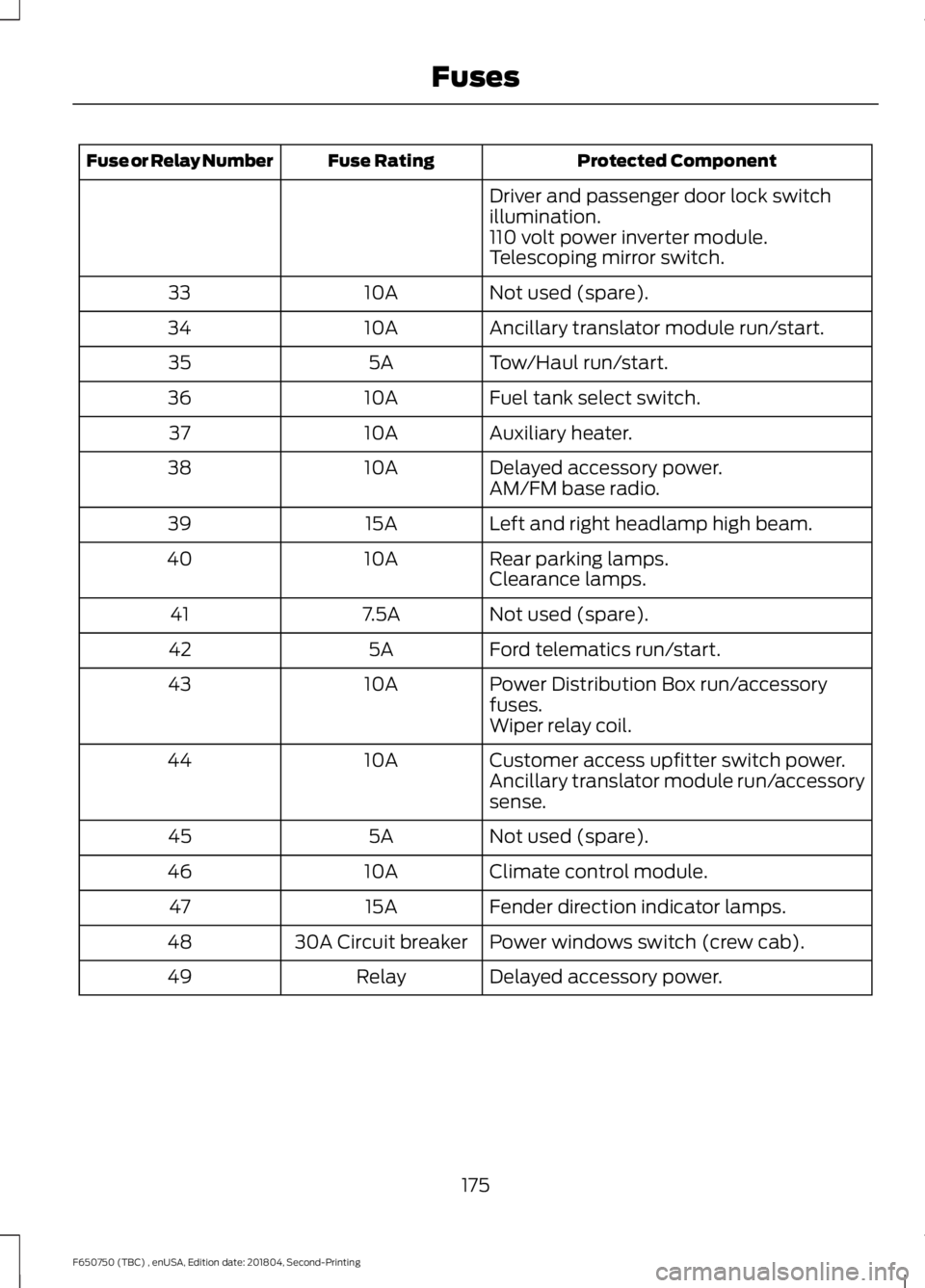
Protected Component
Fuse Rating
Fuse or Relay Number
Driver and passenger door lock switch
illumination.
110 volt power inverter module.
Telescoping mirror switch.
Not used (spare).
10A
33
Ancillary translator module run/start.
10A
34
Tow/Haul run/start.
5A
35
Fuel tank select switch.
10A
36
Auxiliary heater.
10A
37
Delayed accessory power.
10A
38
AM/FM base radio.
Left and right headlamp high beam.
15A
39
Rear parking lamps.
10A
40
Clearance lamps.
Not used (spare).
7.5A
41
Ford telematics run/start.
5A
42
Power Distribution Box run/accessory
fuses.
10A
43
Wiper relay coil.
Customer access upfitter switch power.
10A
44
Ancillary translator module run/accessory
sense.
Not used (spare).
5A
45
Climate control module.
10A
46
Fender direction indicator lamps.
15A
47
Power windows switch (crew cab).
30A Circuit breaker
48
Delayed accessory power.
Relay
49
175
F650750 (TBC) , enUSA, Edition date: 201804, Second-Printing Fuses
Page 185 of 387
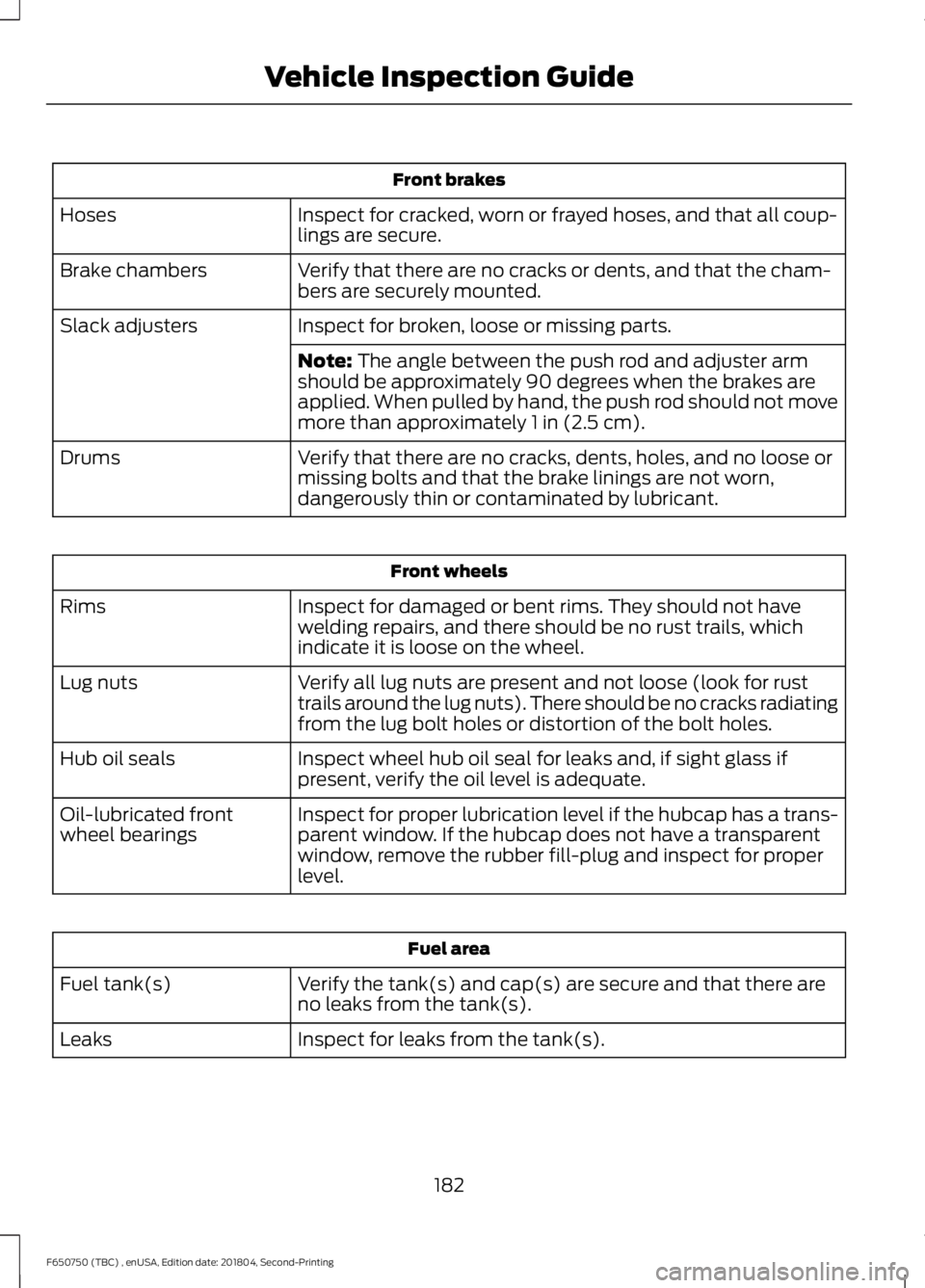
Front brakes
Inspect for cracked, worn or frayed hoses, and that all coup-
lings are secure.
Hoses
Verify that there are no cracks or dents, and that the cham-
bers are securely mounted.
Brake chambers
Inspect for broken, loose or missing parts.
Slack adjusters
Note: The angle between the push rod and adjuster arm
should be approximately 90 degrees when the brakes are
applied. When pulled by hand, the push rod should not move
more than approximately
1 in (2.5 cm).
Verify that there are no cracks, dents, holes, and no loose or
missing bolts and that the brake linings are not worn,
dangerously thin or contaminated by lubricant.
Drums Front wheels
Inspect for damaged or bent rims. They should not have
welding repairs, and there should be no rust trails, which
indicate it is loose on the wheel.
Rims
Verify all lug nuts are present and not loose (look for rust
trails around the lug nuts). There should be no cracks radiating
from the lug bolt holes or distortion of the bolt holes.
Lug nuts
Inspect wheel hub oil seal for leaks and, if sight glass if
present, verify the oil level is adequate.
Hub oil seals
Inspect for proper lubrication level if the hubcap has a trans-
parent window. If the hubcap does not have a transparent
window, remove the rubber fill-plug and inspect for proper
level.
Oil-lubricated front
wheel bearings Fuel area
Verify the tank(s) and cap(s) are secure and that there are
no leaks from the tank(s).
Fuel tank(s)
Inspect for leaks from the tank(s).
Leaks
182
F650750 (TBC) , enUSA, Edition date: 201804, Second-Printing Vehicle Inspection Guide
Page 190 of 387
GENERAL INFORMATION
WARNING: Making modifications
to various parts, components and
systems of the vehicle, such as brake and
steering systems, can adversely affect
the quality, reliability and operation of
your vehicle and could result in property
damage, personal injury or death. Such
modifications must be avoided. WARNING:
Failure to properly
perform maintenance and servicing
procedures could result in vehicle
damage, personal injury or death. WARNING:
Take care when
performing any maintenance, system
check or service on your vehicle. Some
of the materials may also be hazardous
if used, serviced or handled improperly
and could result in property damage,
personal injury or death.
If the owner or operator of the vehicle is a
skilled technician and intends on
performing the vehicle maintenance and
service, he is strongly urged to purchase a
service manual.
Always use care when performing vehicle
maintenance, repairs or system checks.
Improper or incomplete service could result
in your vehicle not working properly which
may result in personal injury or damage to
your vehicle or equipment. It is the
operator ’s responsibility to see that your
vehicle receives proper care and
maintenance. If you have any questions
about performing service, have the service
done by a qualified technician.
To help you service your vehicle, we
provide scheduled maintenance
information which makes tracking routine
service easy. See
Scheduled
Maintenance (page 322). If your vehicle requires professional service,
an authorized dealer can provide the
necessary parts and service. Check your
warranty information to find out which
parts and services are covered.
Use only recommended fuels, lubricants,
fluids and service parts conforming to
specifications. Motorcraft® parts are
designed and built to provide the best
performance in your vehicle.
Servicing Guidelines
WARNING:
The use of inferior
parts can adversely affect the quality
and reliability of your vehicle and could
result in property damage, personal injury
or death.
When servicing your vehicle:
• Always wear safety glasses for eye
protection.
• Always set the parking brake or chock
the wheels.
• Always use support stands, not a jack,
when working under a raised vehicle.
• Always turn off the ignition unless a
procedure requires the engine to be
running.
• Always avoid contact with hot metal
parts. Allow the components to cool
before working with, or around, them.
• Always operate the engine in a
well-ventilated area.
• Do not wear loose-fitting clothing,
hanging jewelry, watches or rings.
• Do not smoke.
• Do not work on the brakes or the clutch
unless you take the proper precautions
to avoid inhaling friction material dust.
187
F650750 (TBC) , enUSA, Edition date: 201804, Second-Printing Maintenance
Page 193 of 387
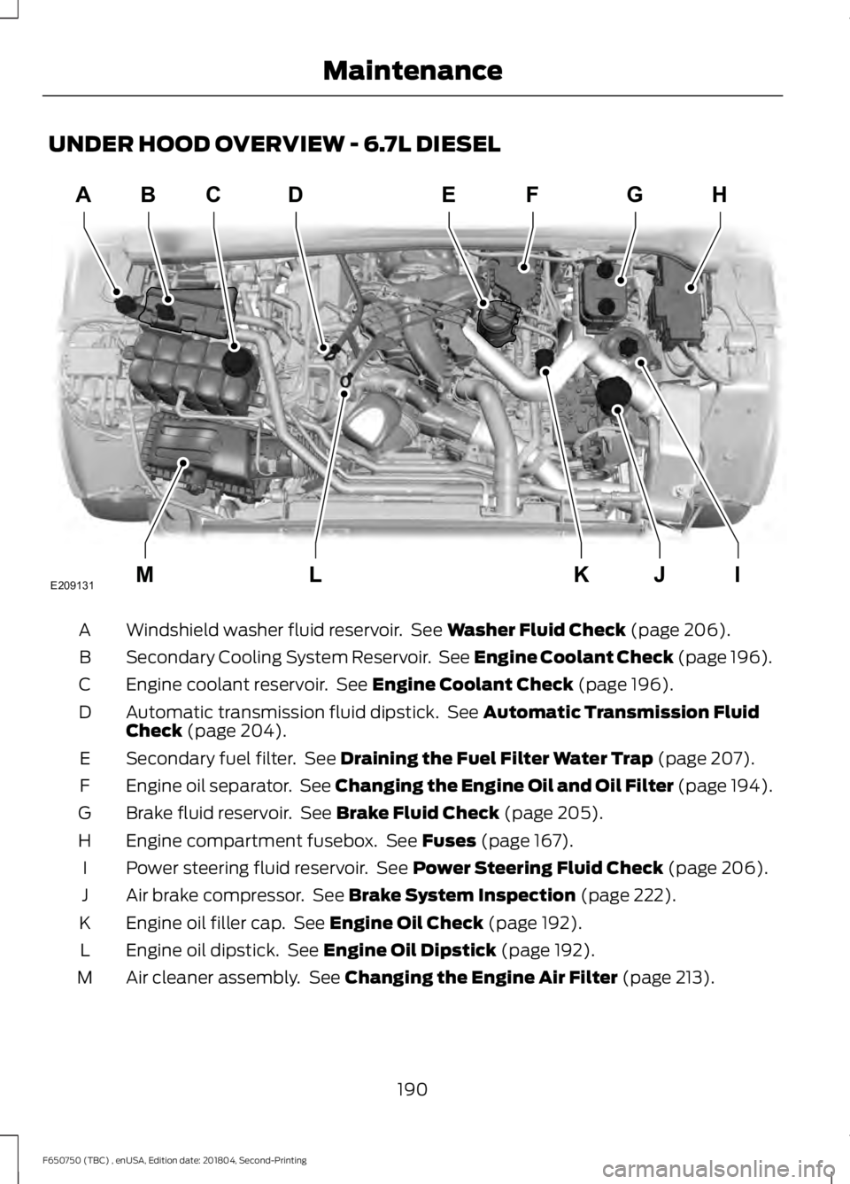
UNDER HOOD OVERVIEW - 6.7L DIESEL
Windshield washer fluid reservoir. See Washer Fluid Check (page 206).
A
Secondary Cooling System Reservoir. See Engine Coolant Check (page 196).
B
Engine coolant reservoir. See
Engine Coolant Check (page 196).
C
Automatic transmission fluid dipstick. See
Automatic Transmission Fluid
Check (page 204).
D
Secondary fuel filter. See
Draining the Fuel Filter Water Trap (page 207).
E
Engine oil separator. See
Changing the Engine Oil and Oil Filter (page 194).
F
Brake fluid reservoir. See
Brake Fluid Check (page 205).
G
Engine compartment fusebox. See
Fuses (page 167).
H
Power steering fluid reservoir. See
Power Steering Fluid Check (page 206).
I
Air brake compressor. See
Brake System Inspection (page 222).
J
Engine oil filler cap. See
Engine Oil Check (page 192).
K
Engine oil dipstick. See
Engine Oil Dipstick (page 192).
L
Air cleaner assembly. See
Changing the Engine Air Filter (page 213).
M
190
F650750 (TBC) , enUSA, Edition date: 201804, Second-Printing MaintenanceABD
IJKLM
FEGH
E209131C
Page 197 of 387
Do not use supplemental engine oil
additives because they are unnecessary
and could lead to engine damage that may
not be covered by the vehicle Warranty.
Only use oils certified for gasoline engines
by the American Petroleum Institute (API).
An oil with this trademark symbol
conforms to the current engine and
emission system protection standards and
fuel economy requirements of the
International Lubricants Specification
Advisory Committee (ILSAC).
To top up the engine oil level do the
following:
1. Clean the area surrounding the engine
oil filler cap before you remove it.
2. Remove the engine oil filler cap.
3. Add engine oil that meets the correct specification.
4. Recheck the oil level.
5. If the oil level is correct, replace the dipstick and make sure it is fully seated.
6. Replace the engine oil filler cap. Turn it clockwise until you feel a strong
resistance.
Note: Do not add oil further than the
maximum mark. Oil levels above the
maximum mark may cause engine damage.
Note: Make sure you install the oil filler cap
correctly. Note:
Soak up any spillage with an
absorbent cloth immediately.
CHANGING THE ENGINE OIL
AND OIL FILTER WARNING: Do not handle a hot
oil filter with bare hands. WARNING:
Continuous contact
with used motor oil has caused cancer
in laboratory mice. Protect your skin by
washing with soap and water.
If your vehicle is equipped with a diesel
engine, an Intelligent Oil Life Monitor™
calculates the proper oil change service
interval. When the information display
indicates: OIL CHANGE REQUIRED, change
the engine oil and oil filter. See
Information Displays
(page 64).
The engine oil filter protects your engine
by filtering harmful, abrasive or sludge
particles and particles significantly smaller
than most available will-fit filters. See
Motorcraft Parts
(page 258).
1. Unscrew the oil filter and oil pan drain plug and wait for the oil to drain.
2. Replace the filter.
3. Reinstall the oil pan drain plug.
4. Refill the engine with new oil. See Capacities and Specifications (page
261
).
5. For diesel engines, you need to reset the Intelligent Oil Life Monitor™. See
Information Displays
(page 64).
194
F650750 (TBC) , enUSA, Edition date: 201804, Second-Printing MaintenanceE142732
Page 198 of 387
Engine lubrication for severe
service operation
The following conditions define severe
operation for which engine operation with
SAE 5W-40 API CJ-4 is recommended. Oil
and oil filter change intervals will be
determined by the Intelligent Oil Life
Monitor™ as noted previously.
•
Frequent or extended idling (over 10
minutes per hour of normal driving).
• Low-speed operation/stationary use.
• If vehicle is operated in sustained
ambient temperatures below -9°F
(-23°C) or above 100°F (38°C).
• Frequent low-speed operation,
consistent heavy traffic less than
25 mph (40 km/h)
.
• Operating in severe dust conditions.
• Operating the vehicle off road.
• Towing a trailer over
1,000 mi
(1,600 km).
• Sustained, high-speed driving at Gross
Vehicle Weight Rating (maximum
loaded weight for vehicle operation).
• Use of fuels with sulfur content other
than ultra-low sulfur diesel (ULSD).
• Use of high-sulfur diesel fuel.
CHANGING THE CRANKCASE
VENT FILTER ELEMENT - 6.7L
DIESEL WARNING:
Do not dispose of
engine oil or oil filters in the household
refuse or the public sewage system. Use
an authorized waste disposal facility.
Do not clean or recondition the filter
element. We recommend that you demand the use
of genuine Ford and Motorcraft® parts
whenever your vehicle requires scheduled
maintenance or repair. Use the correct
specification filter element. See
Motorcraft Parts
(page 257).
Note: Operating your vehicle without a filter
element or with an unapproved filter
element may result in damage to the turbo
charger or exchanger and could lead to
engine damage that may not be covered by
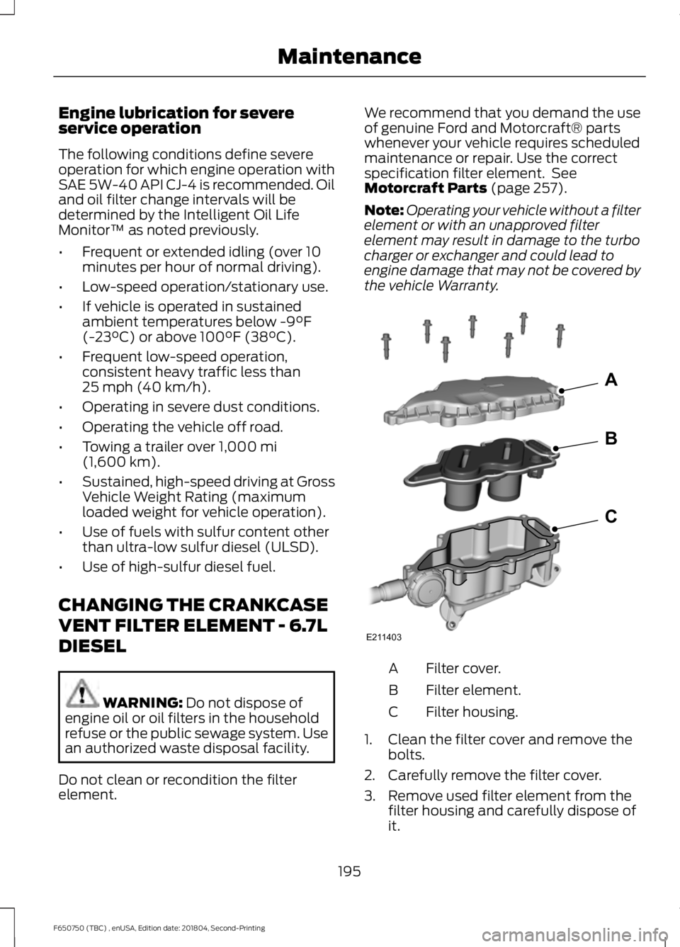
the vehicle Warranty. Filter cover.
A
Filter element.
B
Filter housing.
C
1. Clean the filter cover and remove the bolts.
2. Carefully remove the filter cover.
3. Remove used filter element from the filter housing and carefully dispose of
it.
195
F650750 (TBC) , enUSA, Edition date: 201804, Second-Printing MaintenanceE211403
A
B
C
Page 203 of 387
Engine-driven Cooling Fan
Your vehicle may have an engine driven
cooling fan drive also called a fan clutch.
This fan drive changes the fan speed to
match the vehicle
’s changing cooling air
flow requirements. Fan speed, fan noise
level and fuel consumption all will increase
based on the driving conditions that
include trailer towing, hill climbing, heavy
loads, high speed and high ambient
temperature, individually or in combination.
The fan drive is designed to provide the
minimum fan speed and resulting
minimum fan noise and fuel consumption
required to meet the ever-changing vehicle
cooling air flow requirements. You can hear
the amount of fan noise increasing and
decreasing as the engine power
requirements and vehicle driving conditions
change as you drive. This is normal to the
operation of your vehicle. You may also
hear high levels of the fan when the engine
is first started and should normally
decrease after driving for a short time.
ENGINE COOLANT CHECK -
6.8L WARNING: Do not remove the
coolant reservoir cap when the engine is
on or the cooling system is hot. Wait 10
minutes for the cooling system to cool
down. Cover the coolant reservoir cap
with a thick cloth to prevent the
possibility of scalding and slowly remove
the cap. Failure to follow this instruction
could result in personal injury. WARNING:
Do not put coolant in
the windshield washer reservoir. If
sprayed on the windshield, coolant could
make it difficult to see through the
windshield. WARNING:
To reduce the risk of
personal injury, make sure the engine is
cool before unscrewing the coolant
pressure relief cap. The cooling system
is under pressure. Steam and hot liquid
can come out forcefully when you loosen
the cap slightly. WARNING:
Do not add coolant
further than the MAX mark.
When the engine is cold, check the
concentration and level of the coolant at
the intervals listed in the scheduled
maintenance information. See Scheduled
Maintenance
(page 322).
Note: Make sure that the coolant level is
between the
MIN and the MAX marks on
the coolant reservoir.
Note: Coolant expands when it is hot. The
level may extend beyond the
MAX mark.
Maintain coolant concentration within
48% to 50%, which equates to a freeze
point between -30°F (-34°C) and -34°F
(-37°C). Coolant concentration should be
checked using a refractometer. We
recommend Robinair® Coolant and
Battery Refractometer 75240 (Rotunda
tool part number: ROB75240). We do not
recommend the use of hydrometers or
coolant test strips for measuring coolant
concentration.
Note: Automotive fluids are not
interchangeable. Do not use coolant or
windshield washer fluid outside of its
specified function and vehicle location.
Note: Do not use stop leak pellets, cooling
system sealants, or additives as they can
cause damage to the engine cooling or
heating systems. Resulting component
damage may not be covered by the vehicle
Warranty.
200
F650750 (TBC) , enUSA, Edition date: 201804, Second-Printing Maintenance