2019 FORD F650/750 steering
[x] Cancel search: steeringPage 177 of 387
Protected Component
Fuse Rating
Fuse or Relay Number
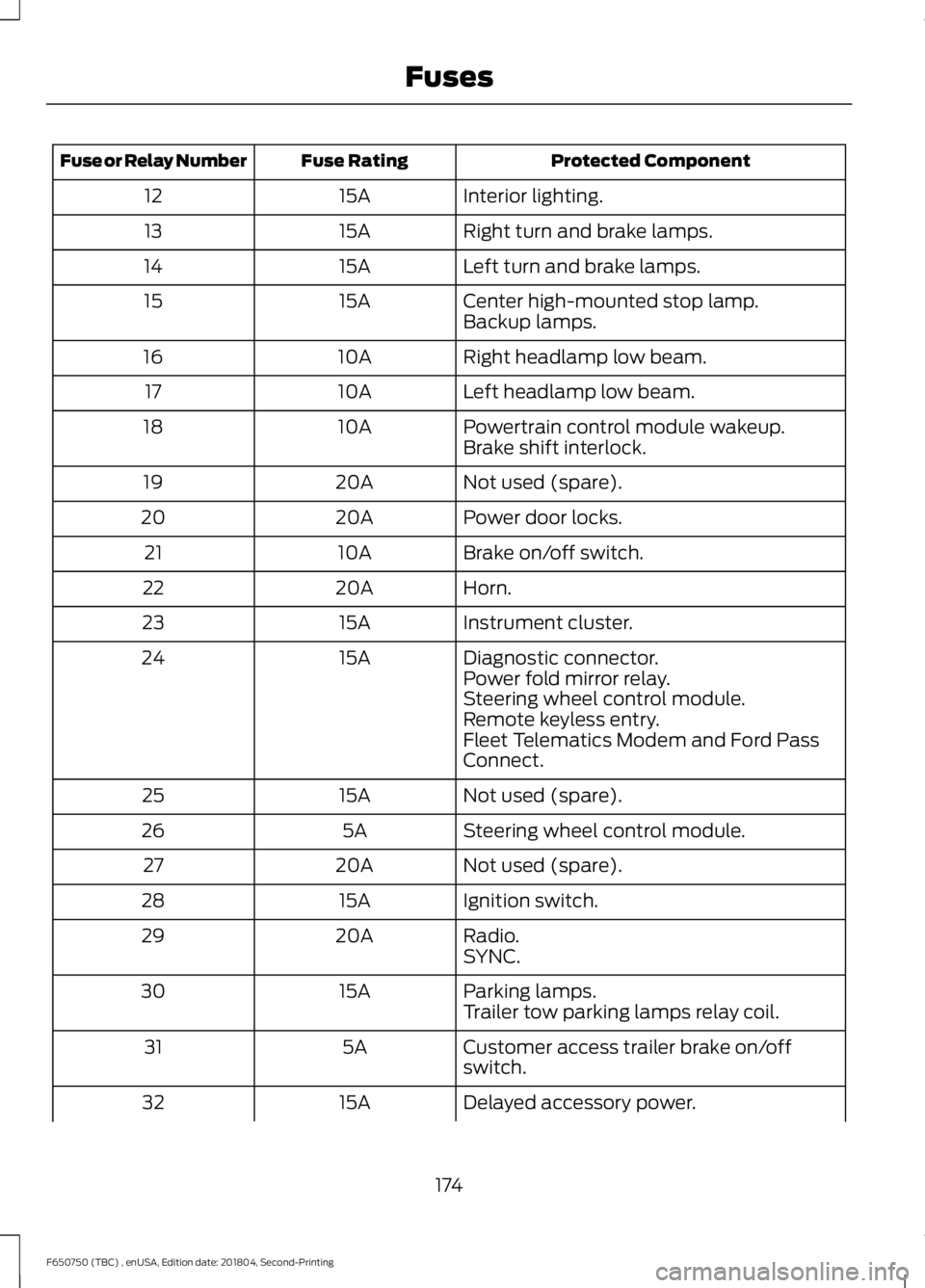
Interior lighting.
15A
12
Right turn and brake lamps.
15A
13
Left turn and brake lamps.
15A
14
Center high-mounted stop lamp.
15A
15
Backup lamps.
Right headlamp low beam.
10A
16
Left headlamp low beam.
10A
17
Powertrain control module wakeup.
10A
18
Brake shift interlock.
Not used (spare).
20A
19
Power door locks.
20A
20
Brake on/off switch.
10A
21
Horn.
20A
22
Instrument cluster.
15A
23
Diagnostic connector.
15A
24
Power fold mirror relay.
Steering wheel control module.
Remote keyless entry.
Fleet Telematics Modem and Ford Pass
Connect.
Not used (spare).
15A
25
Steering wheel control module.
5A
26
Not used (spare).
20A
27
Ignition switch.
15A
28
Radio.
20A
29
SYNC.
Parking lamps.
15A
30
Trailer tow parking lamps relay coil.
Customer access trailer brake on/off
switch.
5A
31
Delayed accessory power.
15A
32
174
F650750 (TBC) , enUSA, Edition date: 201804, Second-Printing Fuses
Page 181 of 387
VEHICLE INSPECTION
INFORMATION
To make sure your vehicle is ready to
operate, conduct a pre-trip inspection at
the beginning of each work period. Follow
the steps listed in this section to verify a
proper vehicle inspection procedure.
WARNING: Exercise great caution
when working on a vehicle equipped with
an automatic fan clutch. The fan starts
in motion only after the engine coolant
reaches a predetermined temperature
or the refrigerant pressure (if equipped
with air conditioning) reaches a
predetermined setting. The fan starts at
this point with no advance warning.
Never reach near, or permit objects to
protrude into, the fan blade radius while
the engine is running as this could result
in vehicle damage, personal injury or
death. WARNING:
Do not operate the
vehicle if any suspension conditions
listed in the following charts are evident.
Loss of steering or suspension could
result in property damage, personal injury
or death. WARNING:
If a wheel must be
changed, obtain expert tire service help.
Mounting and un-mounting of tires
should only be performed by a qualified
technician using necessary safety
procedures and equipment, otherwise
the result could be property damage,
personal injury or death.
Note: Always make sure you apply the
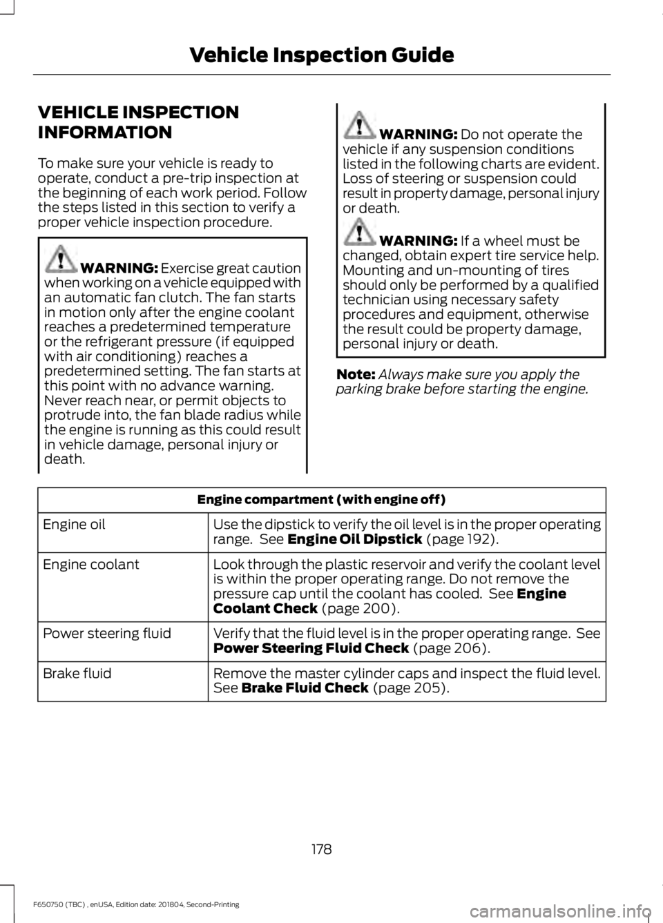
parking brake before starting the engine. Engine compartment (with engine off)
Use the dipstick to verify the oil level is in the proper operating
range. See
Engine Oil Dipstick (page 192).
Engine oil
Look through the plastic reservoir and verify the coolant level
is within the proper operating range. Do not remove the
pressure cap until the coolant has cooled. See
Engine
Coolant Check (page 200).
Engine coolant
Verify that the fluid level is in the proper operating range. See
Power Steering Fluid Check
(page 206).
Power steering fluid
Remove the master cylinder caps and inspect the fluid level.
See
Brake Fluid Check (page 205).
Brake fluid
178
F650750 (TBC) , enUSA, Edition date: 201804, Second-Printing Vehicle Inspection Guide
Page 183 of 387
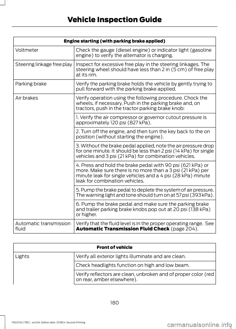
Engine starting (with parking brake applied)
Check the gauge (diesel engine) or indicator light (gasoline
engine) to verify the alternator is charging.
Voltmeter
Inspect for excessive free play in the steering linkages. The
steering wheel should have less than 2 in (5 cm) of free play
at its rim.
Steering linkage free play
Verify the parking brake holds the vehicle by gently trying to
pull forward with the parking brake applied.
Parking brake
Verify operation using the following procedure. Chock the
wheels, if necessary. Push in the parking brake and, on
tractors, push in the tractor parking brake knob:
Air brakes
1. Verify the air compressor or governor cutout pressure is
approximately 120 psi (827 kPa).
2. Turn off the engine, and then turn the key back to the on
position (without starting the engine).
3. Without the brake pedal applied, note the air pressure drop
for one minute. It should be less than 2 psi (14 kPa) for single
vehicles and
3 psi (21 kPa) for combination vehicles.
4. Press and hold the brake pedal with
90 psi (621 kPa) or
more. Make sure there is no more than a 3 psi (21 kPa) per
minute leak for single vehicles and a 4 psi (28 kPa) minute
leak for combination vehicles.
5. Pump the brake pedal to deplete the system of air pressure.
The warning light and tone should turn on at 57 psi (393 kPa).
6. Pump the brake pedal and make sure the parking brake
and trailer parking brake knobs pop out at
20 psi (138 kPa)
or higher.
Verify that the fluid level is in the proper operating range. See
Automatic Transmission Fluid Check
(page 204).
Automatic transmission
fluid Front of vehicle
Verify all exterior lights illuminate and are clean.
Lights
Check headlights function on high and low beam.
Verify reflectors are clean, unbroken and of proper color (red
on rear, amber elsewhere).
180
F650750 (TBC) , enUSA, Edition date: 201804, Second-Printing Vehicle Inspection Guide
Page 184 of 387
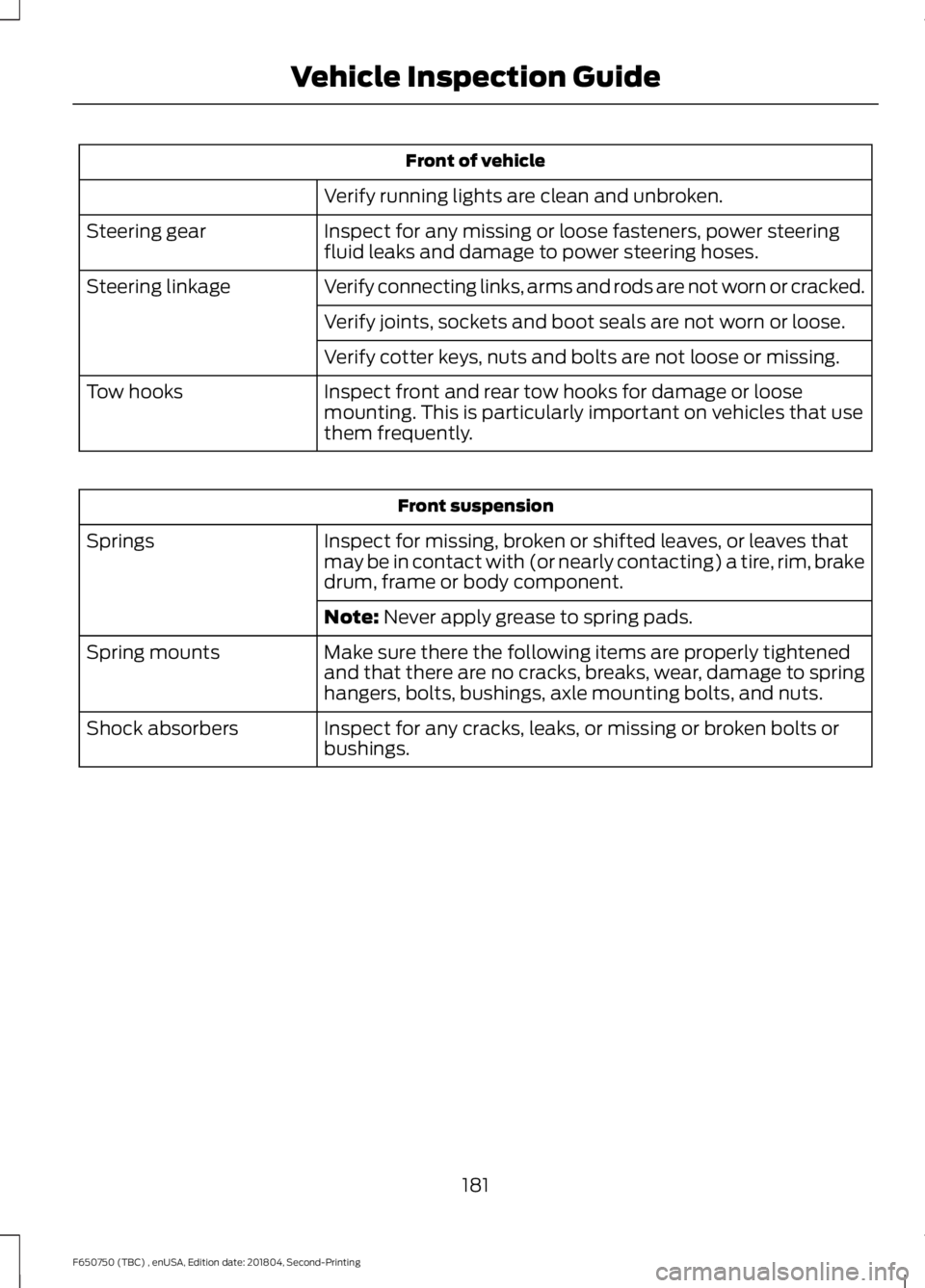
Front of vehicle
Verify running lights are clean and unbroken.
Inspect for any missing or loose fasteners, power steering
fluid leaks and damage to power steering hoses.
Steering gear
Verify connecting links, arms and rods are not worn or cracked.
Steering linkage
Verify joints, sockets and boot seals are not worn or loose.
Verify cotter keys, nuts and bolts are not loose or missing.
Inspect front and rear tow hooks for damage or loose
mounting. This is particularly important on vehicles that use
them frequently.
Tow hooks Front suspension
Inspect for missing, broken or shifted leaves, or leaves that
may be in contact with (or nearly contacting) a tire, rim, brake
drum, frame or body component.
Springs
Note: Never apply grease to spring pads.
Make sure there the following items are properly tightened
and that there are no cracks, breaks, wear, damage to spring
hangers, bolts, bushings, axle mounting bolts, and nuts.
Spring mounts
Inspect for any cracks, leaks, or missing or broken bolts or
bushings.
Shock absorbers
181
F650750 (TBC) , enUSA, Edition date: 201804, Second-Printing Vehicle Inspection Guide
Page 190 of 387
GENERAL INFORMATION
WARNING: Making modifications
to various parts, components and
systems of the vehicle, such as brake and
steering systems, can adversely affect
the quality, reliability and operation of
your vehicle and could result in property
damage, personal injury or death. Such
modifications must be avoided. WARNING:
Failure to properly
perform maintenance and servicing
procedures could result in vehicle
damage, personal injury or death. WARNING:
Take care when
performing any maintenance, system
check or service on your vehicle. Some
of the materials may also be hazardous
if used, serviced or handled improperly
and could result in property damage,
personal injury or death.
If the owner or operator of the vehicle is a
skilled technician and intends on
performing the vehicle maintenance and
service, he is strongly urged to purchase a
service manual.
Always use care when performing vehicle
maintenance, repairs or system checks.
Improper or incomplete service could result
in your vehicle not working properly which
may result in personal injury or damage to
your vehicle or equipment. It is the
operator ’s responsibility to see that your
vehicle receives proper care and
maintenance. If you have any questions
about performing service, have the service
done by a qualified technician.
To help you service your vehicle, we
provide scheduled maintenance
information which makes tracking routine
service easy. See
Scheduled
Maintenance (page 322). If your vehicle requires professional service,
an authorized dealer can provide the
necessary parts and service. Check your
warranty information to find out which
parts and services are covered.
Use only recommended fuels, lubricants,
fluids and service parts conforming to
specifications. Motorcraft® parts are
designed and built to provide the best
performance in your vehicle.
Servicing Guidelines
WARNING:
The use of inferior
parts can adversely affect the quality
and reliability of your vehicle and could
result in property damage, personal injury
or death.
When servicing your vehicle:
• Always wear safety glasses for eye
protection.
• Always set the parking brake or chock
the wheels.
• Always use support stands, not a jack,
when working under a raised vehicle.
• Always turn off the ignition unless a
procedure requires the engine to be
running.
• Always avoid contact with hot metal
parts. Allow the components to cool
before working with, or around, them.
• Always operate the engine in a
well-ventilated area.
• Do not wear loose-fitting clothing,
hanging jewelry, watches or rings.
• Do not smoke.
• Do not work on the brakes or the clutch
unless you take the proper precautions
to avoid inhaling friction material dust.
187
F650750 (TBC) , enUSA, Edition date: 201804, Second-Printing Maintenance
Page 193 of 387
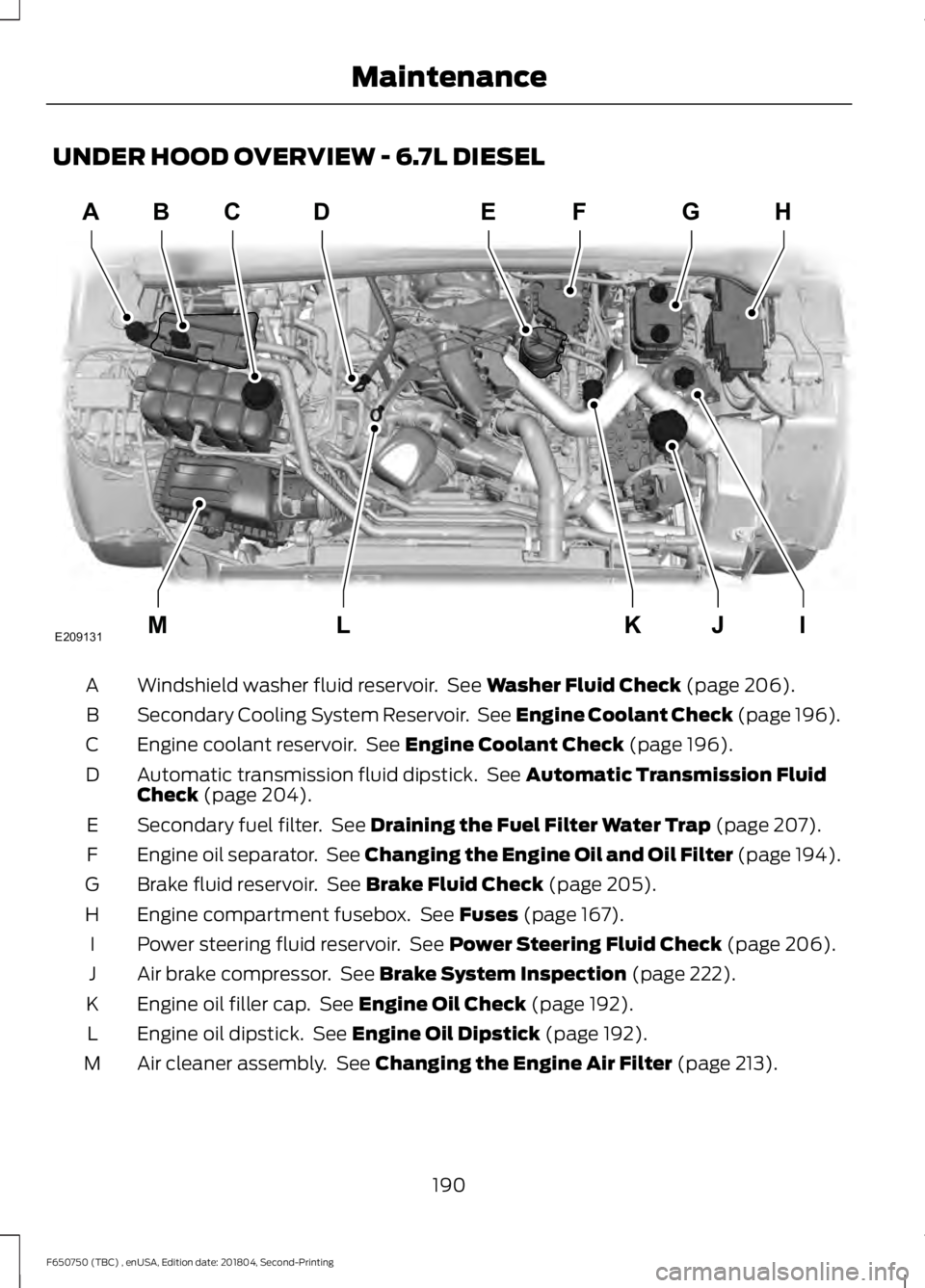
UNDER HOOD OVERVIEW - 6.7L DIESEL
Windshield washer fluid reservoir. See Washer Fluid Check (page 206).
A
Secondary Cooling System Reservoir. See Engine Coolant Check (page 196).
B
Engine coolant reservoir. See
Engine Coolant Check (page 196).
C
Automatic transmission fluid dipstick. See
Automatic Transmission Fluid
Check (page 204).
D
Secondary fuel filter. See
Draining the Fuel Filter Water Trap (page 207).
E
Engine oil separator. See
Changing the Engine Oil and Oil Filter (page 194).
F
Brake fluid reservoir. See
Brake Fluid Check (page 205).
G
Engine compartment fusebox. See
Fuses (page 167).
H
Power steering fluid reservoir. See
Power Steering Fluid Check (page 206).
I
Air brake compressor. See
Brake System Inspection (page 222).
J
Engine oil filler cap. See
Engine Oil Check (page 192).
K
Engine oil dipstick. See
Engine Oil Dipstick (page 192).
L
Air cleaner assembly. See
Changing the Engine Air Filter (page 213).
M
190
F650750 (TBC) , enUSA, Edition date: 201804, Second-Printing MaintenanceABD
IJKLM
FEGH
E209131C
Page 194 of 387
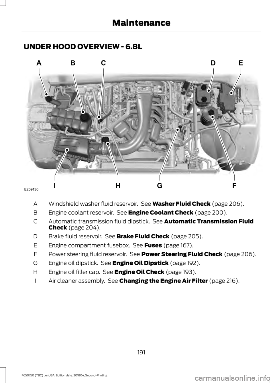
UNDER HOOD OVERVIEW - 6.8L
Windshield washer fluid reservoir. See Washer Fluid Check (page 206).
A
Engine coolant reservoir. See
Engine Coolant Check (page 200).
B
Automatic transmission fluid dipstick. See
Automatic Transmission Fluid
Check (page 204).
C
Brake fluid reservoir. See
Brake Fluid Check (page 205).
D
Engine compartment fusebox. See
Fuses (page 167).
E
Power steering fluid reservoir. See
Power Steering Fluid Check (page 206).
F
Engine oil dipstick. See
Engine Oil Dipstick (page 192).
G
Engine oil filler cap. See
Engine Oil Check (page 193).
H
Air cleaner assembly. See
Changing the Engine Air Filter (page 216).
I
191
F650750 (TBC) , enUSA, Edition date: 201804, Second-Printing MaintenanceABC
FGHI
DE
E209130
Page 199 of 387
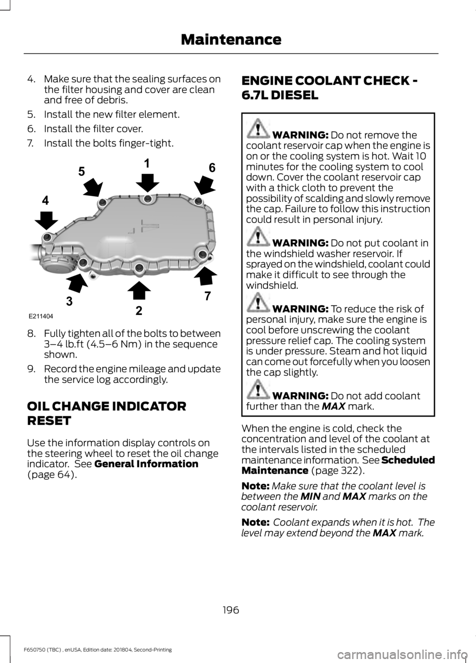
4.
Make sure that the sealing surfaces on
the filter housing and cover are clean
and free of debris.
5. Install the new filter element.
6. Install the filter cover.
7. Install the bolts finger-tight. 8.
Fully tighten all of the bolts to between
3–4 lb.ft (4.5–6 Nm) in the sequence
shown.
9. Record the engine mileage and update
the service log accordingly.
OIL CHANGE INDICATOR
RESET
Use the information display controls on
the steering wheel to reset the oil change
indicator. See
General Information
(page 64). ENGINE COOLANT CHECK -
6.7L DIESEL WARNING:
Do not remove the
coolant reservoir cap when the engine is
on or the cooling system is hot. Wait 10
minutes for the cooling system to cool
down. Cover the coolant reservoir cap
with a thick cloth to prevent the
possibility of scalding and slowly remove
the cap. Failure to follow this instruction
could result in personal injury. WARNING:
Do not put coolant in
the windshield washer reservoir. If
sprayed on the windshield, coolant could
make it difficult to see through the
windshield. WARNING:
To reduce the risk of
personal injury, make sure the engine is
cool before unscrewing the coolant
pressure relief cap. The cooling system
is under pressure. Steam and hot liquid
can come out forcefully when you loosen
the cap slightly. WARNING:
Do not add coolant
further than the MAX mark.
When the engine is cold, check the
concentration and level of the coolant at
the intervals listed in the scheduled
maintenance information. See Scheduled
Maintenance
(page 322).
Note: Make sure that the coolant level is
between the
MIN and MAX marks on the
coolant reservoir.
Note: Coolant expands when it is hot. The
level may extend beyond the
MAX mark.
196
F650750 (TBC) , enUSA, Edition date: 201804, Second-Printing MaintenanceE211404
165
4
32
7