2019 FORD F650/750 check engine light
[x] Cancel search: check engine lightPage 150 of 387
•
Shift to a lower gear when driving down
a long or steep hill. Do not apply the
brakes continuously, as they may
overheat and become less effective.
• If your transmission is equipped with
the Tow/Haul feature, use this feature
when towing. This provides engine
braking and helps eliminate excessive
transmission shifting for optimum fuel
economy and transmission cooling.
• Allow more distance for stopping with
a trailer attached. Anticipate stops and
brake gradually.
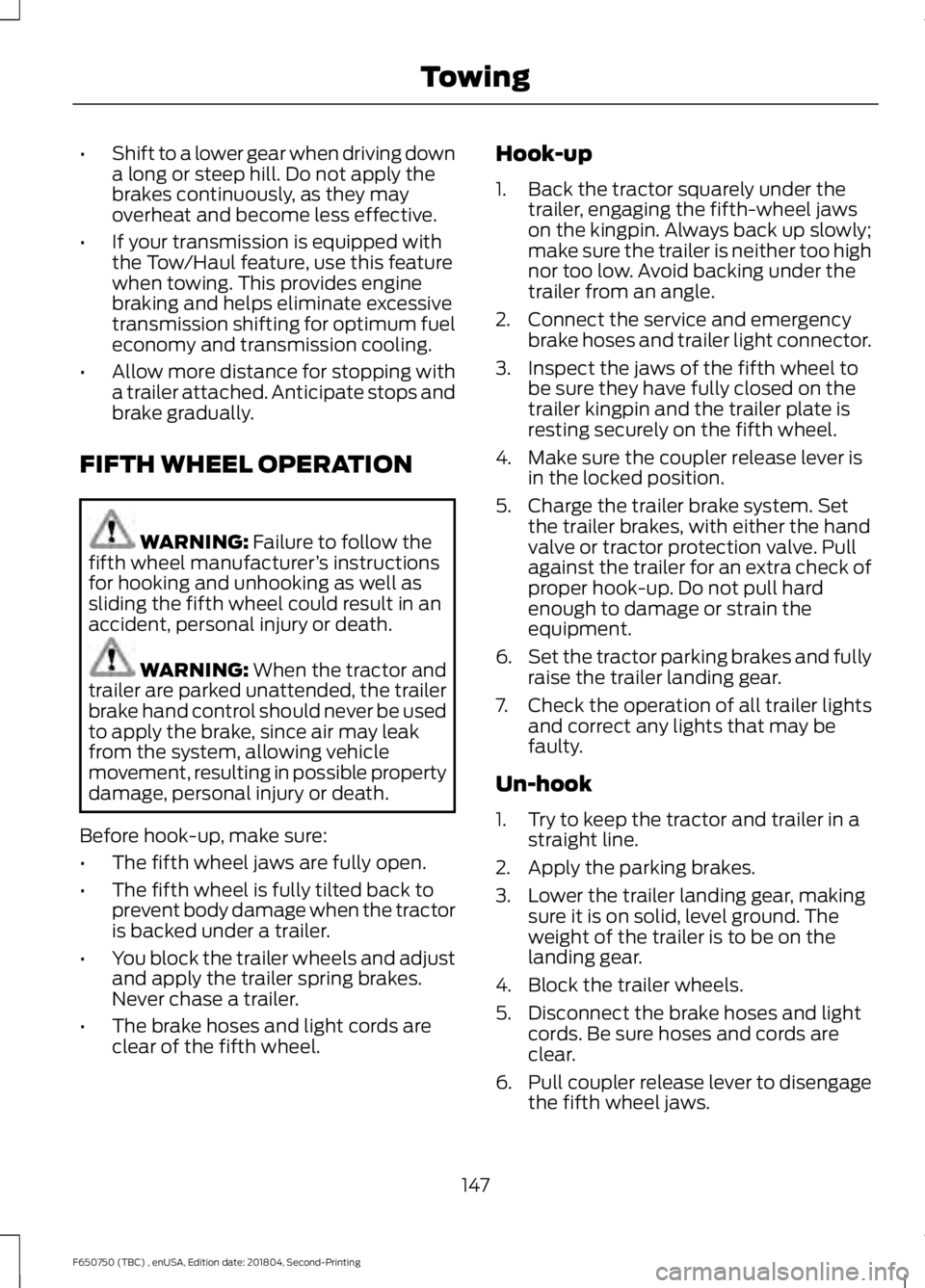
FIFTH WHEEL OPERATION WARNING: Failure to follow the
fifth wheel manufacturer ’s instructions
for hooking and unhooking as well as
sliding the fifth wheel could result in an
accident, personal injury or death. WARNING:
When the tractor and
trailer are parked unattended, the trailer
brake hand control should never be used
to apply the brake, since air may leak
from the system, allowing vehicle
movement, resulting in possible property
damage, personal injury or death.
Before hook-up, make sure:
• The fifth wheel jaws are fully open.
• The fifth wheel is fully tilted back to
prevent body damage when the tractor
is backed under a trailer.
• You block the trailer wheels and adjust
and apply the trailer spring brakes.
Never chase a trailer.
• The brake hoses and light cords are
clear of the fifth wheel. Hook-up
1. Back the tractor squarely under the
trailer, engaging the fifth-wheel jaws
on the kingpin. Always back up slowly;
make sure the trailer is neither too high
nor too low. Avoid backing under the
trailer from an angle.
2. Connect the service and emergency brake hoses and trailer light connector.
3. Inspect the jaws of the fifth wheel to be sure they have fully closed on the
trailer kingpin and the trailer plate is
resting securely on the fifth wheel.
4. Make sure the coupler release lever is in the locked position.
5. Charge the trailer brake system. Set the trailer brakes, with either the hand
valve or tractor protection valve. Pull
against the trailer for an extra check of
proper hook-up. Do not pull hard
enough to damage or strain the
equipment.
6. Set the tractor parking brakes and fully
raise the trailer landing gear.
7. Check the operation of all trailer lights
and correct any lights that may be
faulty.
Un-hook
1. Try to keep the tractor and trailer in a straight line.
2. Apply the parking brakes.
3. Lower the trailer landing gear, making sure it is on solid, level ground. The
weight of the trailer is to be on the
landing gear.
4. Block the trailer wheels.
5. Disconnect the brake hoses and light cords. Be sure hoses and cords are
clear.
6. Pull coupler release lever to disengage
the fifth wheel jaws.
147
F650750 (TBC) , enUSA, Edition date: 201804, Second-Printing Towing
Page 156 of 387
Operation in Snow and Rain
Vehicle operation in heavy snowfall or
extreme rain conditions may feed
excessive amounts of snow or water into
the air intake system. This could plug the
air filter with snow and may cause the
engine to lose power and possibly shut
down.
We recommend the following actions after
operating your vehicle up to 199 mi
(320 km) in snowfall or extreme rain:
• Snow: At the earliest opportunity, open
the hood and clear all the snow and ice
from the air filter housing inlet (do not
remove the foam filter) and reset the
air filter restriction gauge.
Note: Removal of the foam filter degrades
your vehicle performance during snow and
hot weather conditions.
• Extreme rain: The air filter dries after
about 15– 30 minutes at highway
speeds. At the earliest opportunity,
open the hood and reset the air filter
restriction gauge.
DRIVING THROUGH WATER WARNING:
Do not drive through
flowing or deep water as you may lose
control of your vehicle.
Note: Driving through standing water can
cause vehicle damage.
Note: Engine damage can occur if water
enters the air filter.
Before driving through standing water,
check the depth. Never drive through water
that is higher than the bottom of the wheel
hubs. When driving through standing water, drive
very slowly and do not stop your vehicle.
Your brake performance and traction may
be limited. After driving through water and
as soon as it is safe to do so:
•
Lightly press the brake pedal to dry the
brakes and to check that they work.
• Check that the horn works.
• Check that the exterior lights work.
• Turn the steering wheel to check that
the steering power assist works.
Operation in Standing Water
Ingestion of water into the diesel engine
can result in immediate and severe
damage to the engine. If driving through
water, slow down to avoid splashing water
into the intake. If the engine stalls, and you
suspect ingestion of water into the engine,
do not try to restart the engine. Consult
your dealer for service immediately.
Your fuel tank vents to the atmosphere by
valves on top of the tank and through the
fuel cap. If water reaches the top of the
tank, the valves may pull water into the
fuel tank. Water in the fuel can cause
performance issues and damage the fuel
injection system.
153
F650750 (TBC) , enUSA, Edition date: 201804, Second-Printing Driving HintsE176913
Page 183 of 387
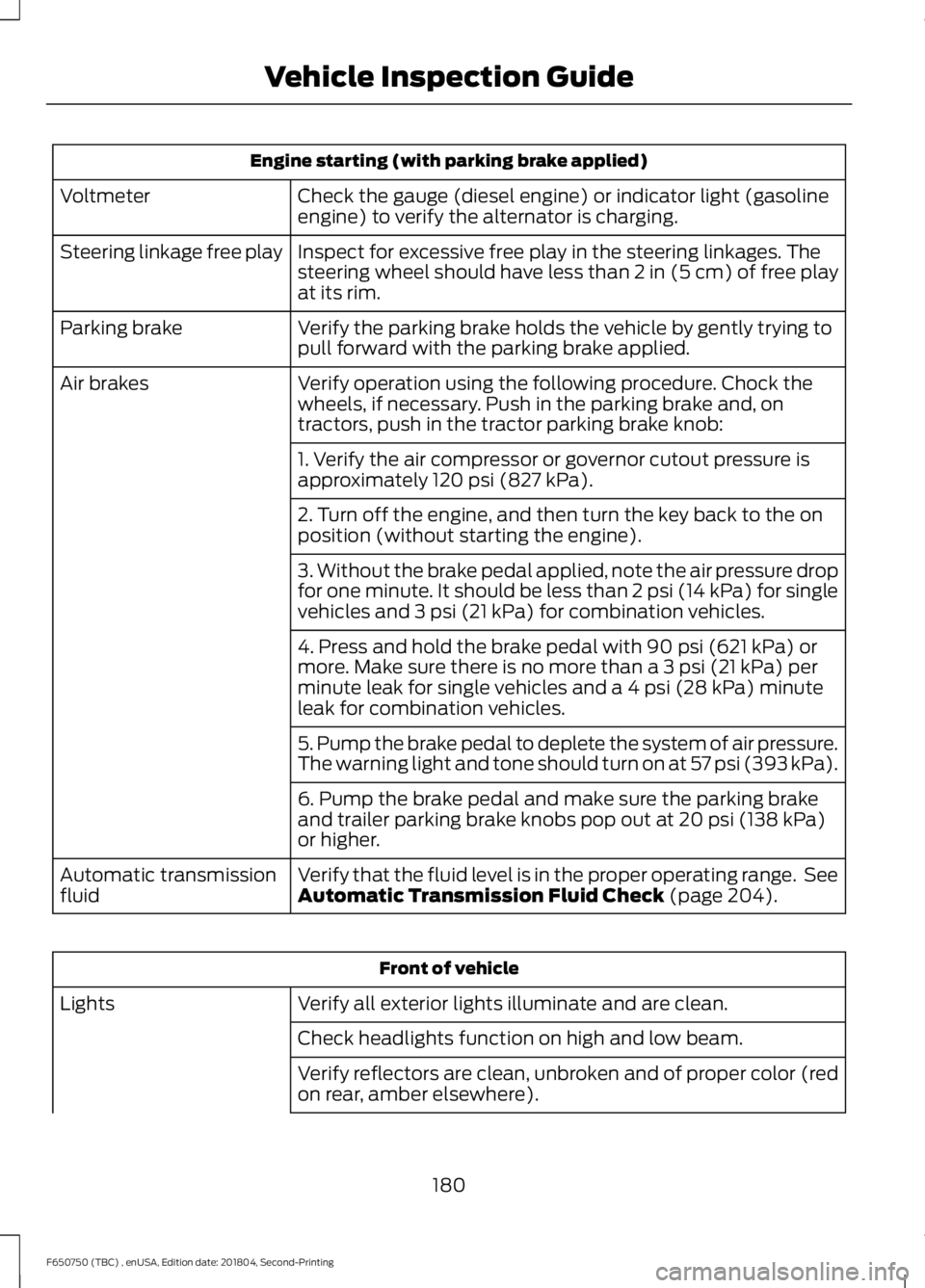
Engine starting (with parking brake applied)
Check the gauge (diesel engine) or indicator light (gasoline
engine) to verify the alternator is charging.
Voltmeter
Inspect for excessive free play in the steering linkages. The
steering wheel should have less than 2 in (5 cm) of free play
at its rim.
Steering linkage free play
Verify the parking brake holds the vehicle by gently trying to
pull forward with the parking brake applied.
Parking brake
Verify operation using the following procedure. Chock the
wheels, if necessary. Push in the parking brake and, on
tractors, push in the tractor parking brake knob:
Air brakes
1. Verify the air compressor or governor cutout pressure is
approximately 120 psi (827 kPa).
2. Turn off the engine, and then turn the key back to the on
position (without starting the engine).
3. Without the brake pedal applied, note the air pressure drop
for one minute. It should be less than 2 psi (14 kPa) for single
vehicles and
3 psi (21 kPa) for combination vehicles.
4. Press and hold the brake pedal with
90 psi (621 kPa) or
more. Make sure there is no more than a 3 psi (21 kPa) per
minute leak for single vehicles and a 4 psi (28 kPa) minute
leak for combination vehicles.
5. Pump the brake pedal to deplete the system of air pressure.
The warning light and tone should turn on at 57 psi (393 kPa).
6. Pump the brake pedal and make sure the parking brake
and trailer parking brake knobs pop out at
20 psi (138 kPa)
or higher.
Verify that the fluid level is in the proper operating range. See
Automatic Transmission Fluid Check
(page 204).
Automatic transmission
fluid Front of vehicle
Verify all exterior lights illuminate and are clean.
Lights
Check headlights function on high and low beam.
Verify reflectors are clean, unbroken and of proper color (red
on rear, amber elsewhere).
180
F650750 (TBC) , enUSA, Edition date: 201804, Second-Printing Vehicle Inspection Guide
Page 188 of 387
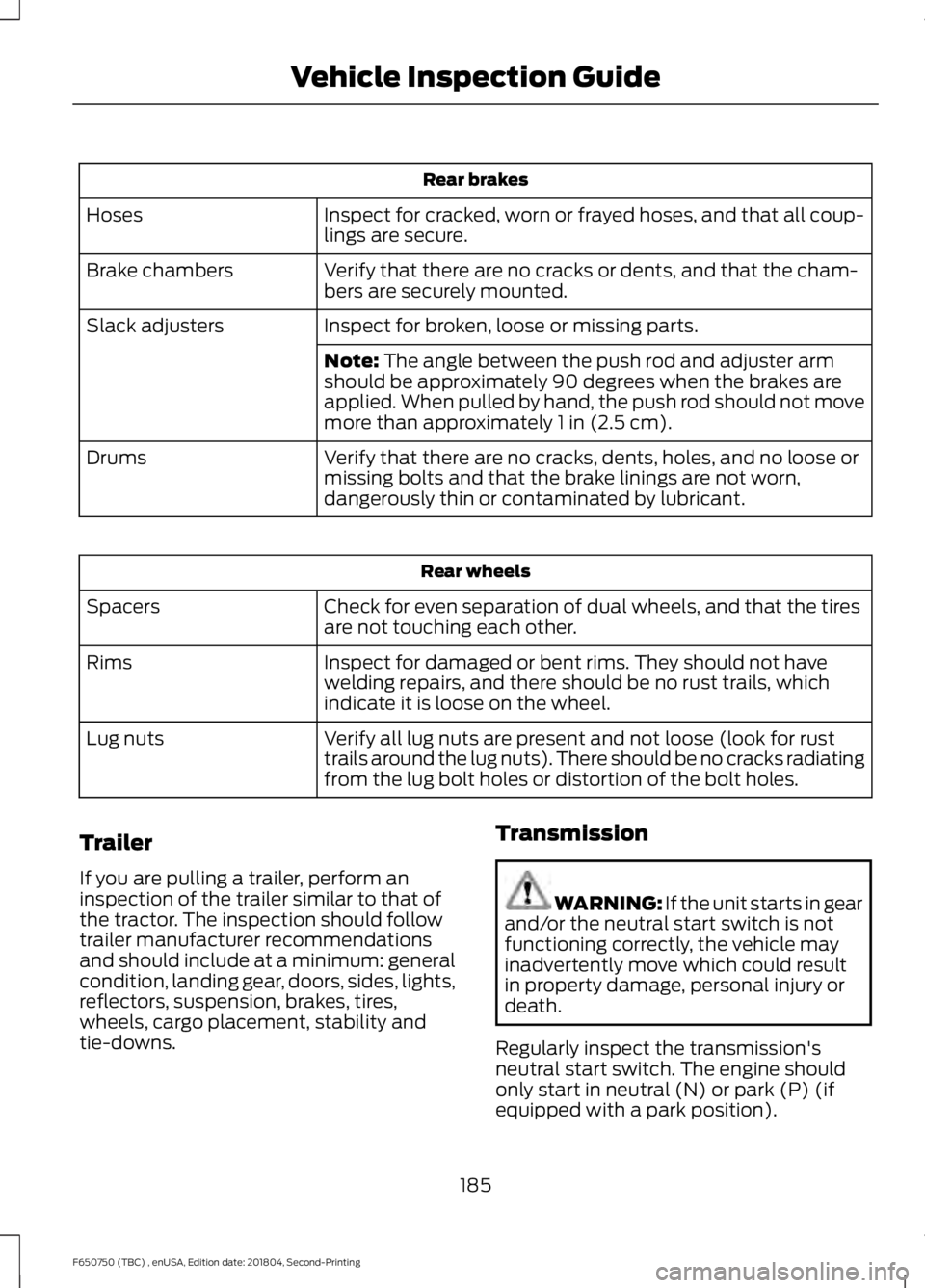
Rear brakes
Inspect for cracked, worn or frayed hoses, and that all coup-
lings are secure.
Hoses
Verify that there are no cracks or dents, and that the cham-
bers are securely mounted.
Brake chambers
Inspect for broken, loose or missing parts.
Slack adjusters
Note: The angle between the push rod and adjuster arm
should be approximately 90 degrees when the brakes are
applied. When pulled by hand, the push rod should not move
more than approximately
1 in (2.5 cm).
Verify that there are no cracks, dents, holes, and no loose or
missing bolts and that the brake linings are not worn,
dangerously thin or contaminated by lubricant.
Drums Rear wheels
Check for even separation of dual wheels, and that the tires
are not touching each other.
Spacers
Inspect for damaged or bent rims. They should not have
welding repairs, and there should be no rust trails, which
indicate it is loose on the wheel.
Rims
Verify all lug nuts are present and not loose (look for rust
trails around the lug nuts). There should be no cracks radiating
from the lug bolt holes or distortion of the bolt holes.
Lug nuts
Trailer
If you are pulling a trailer, perform an
inspection of the trailer similar to that of
the tractor. The inspection should follow
trailer manufacturer recommendations
and should include at a minimum: general
condition, landing gear, doors, sides, lights,
reflectors, suspension, brakes, tires,
wheels, cargo placement, stability and
tie-downs. Transmission WARNING: If the unit starts in gear
and/or the neutral start switch is not
functioning correctly, the vehicle may
inadvertently move which could result
in property damage, personal injury or
death.
Regularly inspect the transmission's
neutral start switch. The engine should
only start in neutral (N) or park (P) (if
equipped with a park position).
185
F650750 (TBC) , enUSA, Edition date: 201804, Second-Printing Vehicle Inspection Guide
Page 199 of 387
4.
Make sure that the sealing surfaces on
the filter housing and cover are clean
and free of debris.
5. Install the new filter element.
6. Install the filter cover.
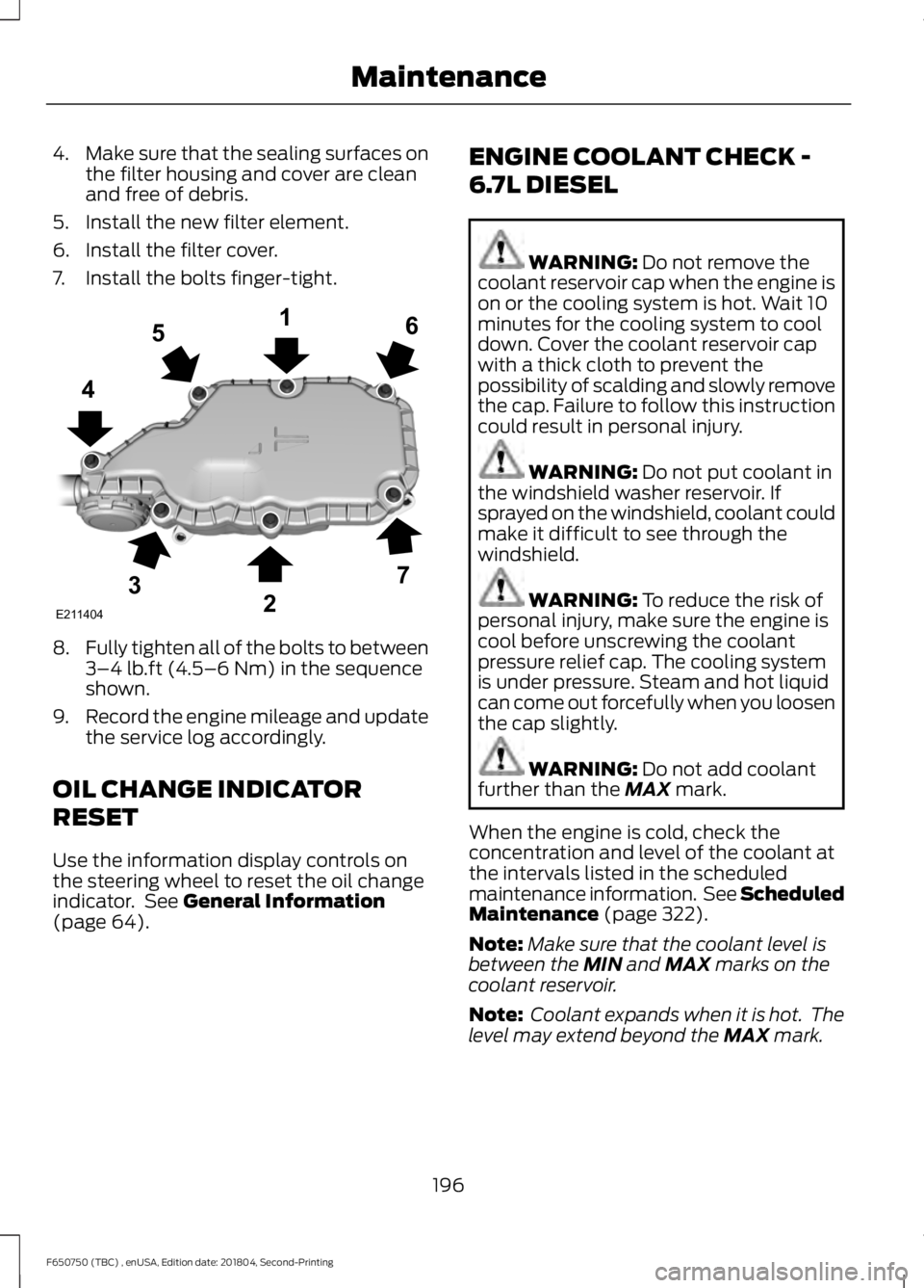
7. Install the bolts finger-tight. 8.
Fully tighten all of the bolts to between
3–4 lb.ft (4.5–6 Nm) in the sequence
shown.
9. Record the engine mileage and update
the service log accordingly.
OIL CHANGE INDICATOR
RESET
Use the information display controls on
the steering wheel to reset the oil change
indicator. See
General Information
(page 64). ENGINE COOLANT CHECK -
6.7L DIESEL WARNING:
Do not remove the
coolant reservoir cap when the engine is
on or the cooling system is hot. Wait 10
minutes for the cooling system to cool
down. Cover the coolant reservoir cap
with a thick cloth to prevent the
possibility of scalding and slowly remove
the cap. Failure to follow this instruction
could result in personal injury. WARNING:
Do not put coolant in
the windshield washer reservoir. If
sprayed on the windshield, coolant could
make it difficult to see through the
windshield. WARNING:
To reduce the risk of
personal injury, make sure the engine is
cool before unscrewing the coolant
pressure relief cap. The cooling system
is under pressure. Steam and hot liquid
can come out forcefully when you loosen
the cap slightly. WARNING:
Do not add coolant
further than the MAX mark.
When the engine is cold, check the
concentration and level of the coolant at
the intervals listed in the scheduled
maintenance information. See Scheduled
Maintenance
(page 322).
Note: Make sure that the coolant level is
between the
MIN and MAX marks on the
coolant reservoir.
Note: Coolant expands when it is hot. The
level may extend beyond the
MAX mark.
196
F650750 (TBC) , enUSA, Edition date: 201804, Second-Printing MaintenanceE211404
165
4
32
7
Page 203 of 387
Engine-driven Cooling Fan
Your vehicle may have an engine driven
cooling fan drive also called a fan clutch.
This fan drive changes the fan speed to
match the vehicle
’s changing cooling air
flow requirements. Fan speed, fan noise
level and fuel consumption all will increase
based on the driving conditions that
include trailer towing, hill climbing, heavy
loads, high speed and high ambient
temperature, individually or in combination.
The fan drive is designed to provide the
minimum fan speed and resulting
minimum fan noise and fuel consumption
required to meet the ever-changing vehicle
cooling air flow requirements. You can hear
the amount of fan noise increasing and
decreasing as the engine power
requirements and vehicle driving conditions
change as you drive. This is normal to the
operation of your vehicle. You may also
hear high levels of the fan when the engine
is first started and should normally
decrease after driving for a short time.
ENGINE COOLANT CHECK -
6.8L WARNING: Do not remove the
coolant reservoir cap when the engine is
on or the cooling system is hot. Wait 10
minutes for the cooling system to cool
down. Cover the coolant reservoir cap
with a thick cloth to prevent the
possibility of scalding and slowly remove
the cap. Failure to follow this instruction
could result in personal injury. WARNING:
Do not put coolant in
the windshield washer reservoir. If
sprayed on the windshield, coolant could
make it difficult to see through the
windshield. WARNING:
To reduce the risk of
personal injury, make sure the engine is
cool before unscrewing the coolant
pressure relief cap. The cooling system
is under pressure. Steam and hot liquid
can come out forcefully when you loosen
the cap slightly. WARNING:
Do not add coolant
further than the MAX mark.
When the engine is cold, check the
concentration and level of the coolant at
the intervals listed in the scheduled
maintenance information. See Scheduled
Maintenance
(page 322).
Note: Make sure that the coolant level is
between the
MIN and the MAX marks on
the coolant reservoir.
Note: Coolant expands when it is hot. The
level may extend beyond the
MAX mark.
Maintain coolant concentration within
48% to 50%, which equates to a freeze
point between -30°F (-34°C) and -34°F
(-37°C). Coolant concentration should be
checked using a refractometer. We
recommend Robinair® Coolant and
Battery Refractometer 75240 (Rotunda
tool part number: ROB75240). We do not
recommend the use of hydrometers or
coolant test strips for measuring coolant
concentration.
Note: Automotive fluids are not
interchangeable. Do not use coolant or
windshield washer fluid outside of its
specified function and vehicle location.
Note: Do not use stop leak pellets, cooling
system sealants, or additives as they can
cause damage to the engine cooling or
heating systems. Resulting component
damage may not be covered by the vehicle
Warranty.
200
F650750 (TBC) , enUSA, Edition date: 201804, Second-Printing Maintenance
Page 210 of 387
DRAINING THE FUEL FILTER
WATER TRAP - 6.7L DIESEL
Your vehicle is equipped with a diesel fuel
conditioner module located on the
frame-rail under the driver-side floorboard
near the transmission.
You should drain water from the
module assembly whenever the
warning light comes on and the
message center directs you to drain the
water separator. This will occur when
approximately 8.45 fl oz (250 ml) of water
accumulates in the module. If you allow
the water level to exceed this level, the
water may pass through to the engine and
may cause fuel injection equipment
damage.
Draining the Diesel Fuel
Conditioner Module (DFCM) WARNING: Do not drain the
water-in-fuel separator while the engine
is running. Failure to follow this warning
may result in fire, serious injury, death or
property damage.
Note: If you drain the diesel fuel conditioner
module while the system is running air will
enter into the fuel system. The engine will
not operate properly if air enters the system.
Note: With fuel tank levels above 3⁄4 tank
it may be necessary to loosen the bowl three
turns before opening the drain. This will
actuate an anti-siphon valve at the fuel and
water separator inlet and prevent the fuel
from siphoning out of the tank.
Note: A loose drain valve can allow air to
enter the fuel system and cause drivetrain
issues. The engine will not operate properly.
Be sure that you fully tighten the drain valve.
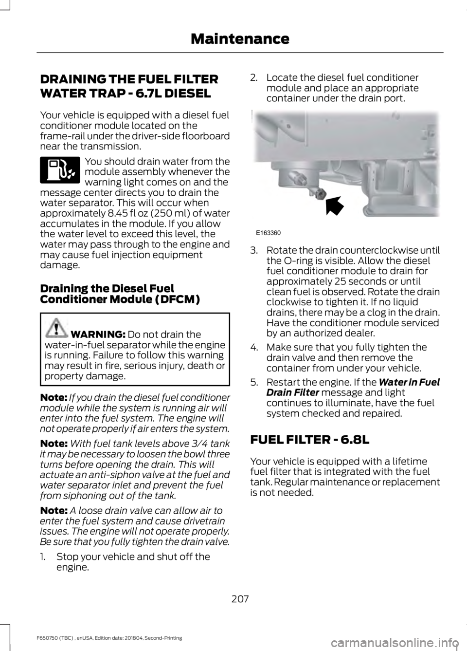
1. Stop your vehicle and shut off the engine. 2. Locate the diesel fuel conditioner
module and place an appropriate
container under the drain port. 3.
Rotate the drain counterclockwise until
the O-ring is visible. Allow the diesel
fuel conditioner module to drain for
approximately 25 seconds or until
clean fuel is observed. Rotate the drain
clockwise to tighten it. If no liquid
drains, there may be a clog in the drain.
Have the conditioner module serviced
by an authorized dealer.
4. Make sure that you fully tighten the drain valve and then remove the
container from under your vehicle.
5. Restart the engine. If the Water in Fuel
Drain Filter
message and light
continues to illuminate, have the fuel
system checked and repaired.
FUEL FILTER - 6.8L
Your vehicle is equipped with a lifetime
fuel filter that is integrated with the fuel
tank. Regular maintenance or replacement
is not needed.
207
F650750 (TBC) , enUSA, Edition date: 201804, Second-Printing Maintenance E163360
Page 327 of 387
There are three types of maintenance
intervals for general vehicle environments:
On-Highway, City and Severe Service. In
all applications, monitoring miles
(kilometers) and time and when the engine
is due for an oil change determine the
actual interval. When the engine oil change
is required before the truck lubrication
interval, perform the lubrication at the
same time in order to reduce your vehicle
’s
time out of service.
Air Brake Adjustment WARNING: Failure to maintain
proper air brake adjustment can result
in reduction or loss of braking ability.
A qualified service technician, keeping to
the instructions in the service manual,
should perform air brake inspection and
adjustment or repairs.
Cam Brakes - Automatic Slack
Adjusters WARNING:
Do not manually
adjust the automatic slack adjusters to
correct excessive push rod stroke as it
may result in reduced brake
effectiveness and a vehicle crash.
Excessive push rod stroke indicates that a problem exists with the automatic
adjuster, with the installation of the
adjuster, or with foundation brake
components that manual adjustment
does not remedy. Seek service from a
qualified facility for excessive push rod
stroke.
Inspect standard air brakes equipped with
automatic slack adjusters for proper brake
adjustment as listed in the maintenance
schedule charts.
However, inspect the brakes more
frequently when subjecting them to heavy
use or adverse operating conditions such
as:
• Frequent brake applications while fully
loaded.
• Operation on hilly or mountainous
terrain.
• Frequent operation on dirt, gravel or
mud.
Some aftermarket brake linings also
require more frequent inspections.
Owner Checks and Services
Make sure you perform the following basic
maintenance checks and inspections every
month or at six-month intervals. Check Every Month
Air filter restriction gauge. 1
Engine oil level.
Fuel and water separator. Drain if necessary, or if indicated by the information display. 1
Function of all interior and exterior lights.
Holes and slots in the tail pipe to make sure they are functional and clear of debris. 1
324
F650750 (TBC) , enUSA, Edition date: 201804, Second-Printing Scheduled Maintenance