2019 FORD F650/750 clock
[x] Cancel search: clockPage 214 of 387
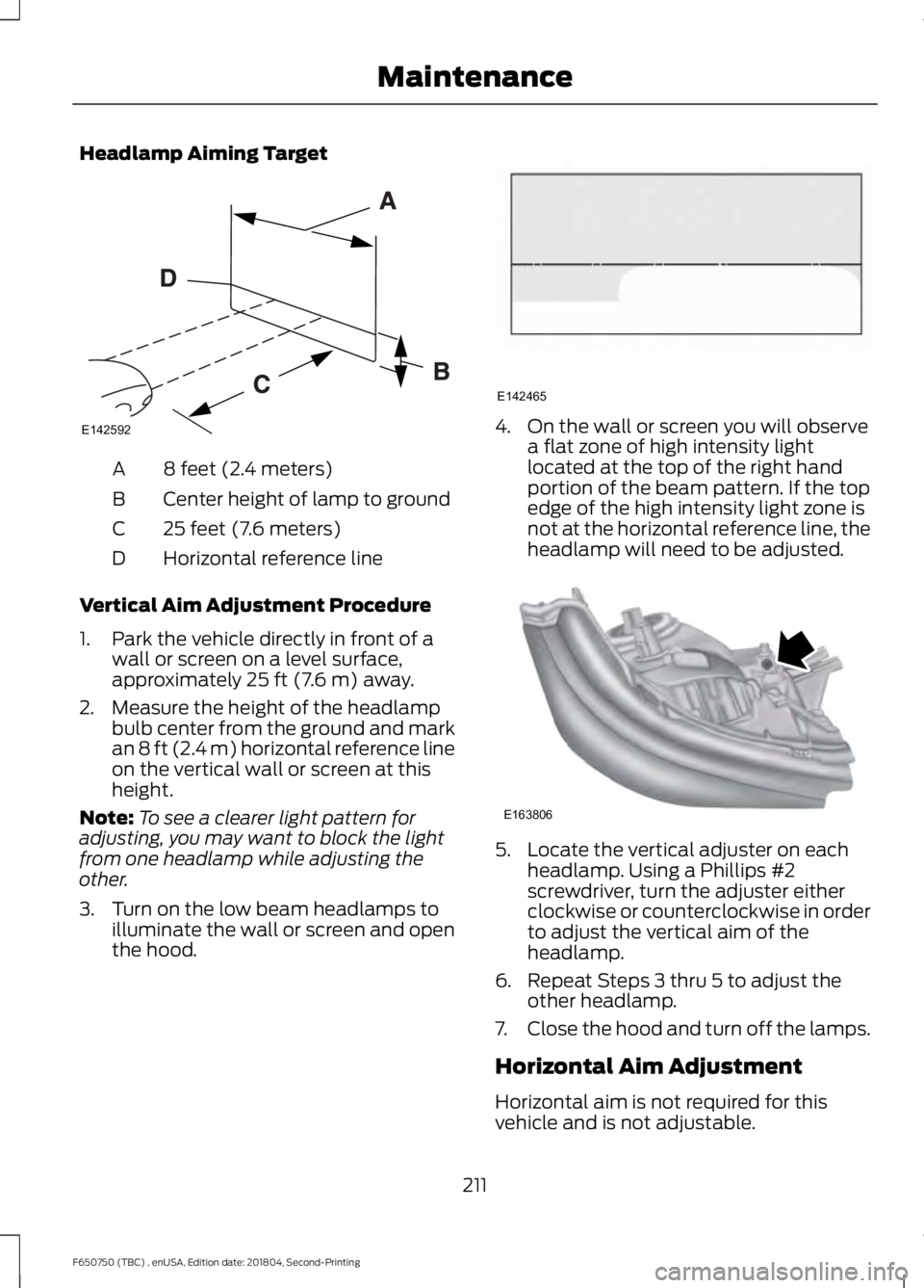
Headlamp Aiming Target
8 feet (2.4 meters)
A
Center height of lamp to ground
B
25 feet (7.6 meters)
C
Horizontal reference line
D
Vertical Aim Adjustment Procedure
1. Park the vehicle directly in front of a wall or screen on a level surface,
approximately 25 ft (7.6 m) away.
2. Measure the height of the headlamp bulb center from the ground and mark
an
8 ft (2.4 m) horizontal reference line
on the vertical wall or screen at this
height.
Note: To see a clearer light pattern for
adjusting, you may want to block the light
from one headlamp while adjusting the
other.
3. Turn on the low beam headlamps to illuminate the wall or screen and open
the hood. 4. On the wall or screen you will observe
a flat zone of high intensity light
located at the top of the right hand
portion of the beam pattern. If the top
edge of the high intensity light zone is
not at the horizontal reference line, the
headlamp will need to be adjusted. 5. Locate the vertical adjuster on each
headlamp. Using a Phillips #2
screwdriver, turn the adjuster either
clockwise or counterclockwise in order
to adjust the vertical aim of the
headlamp.
6. Repeat Steps 3 thru 5 to adjust the other headlamp.
7. Close the hood and turn off the lamps.
Horizontal Aim Adjustment
Horizontal aim is not required for this
vehicle and is not adjustable.
211
F650750 (TBC) , enUSA, Edition date: 201804, Second-Printing MaintenanceE142592 E142465 E163806
Page 215 of 387
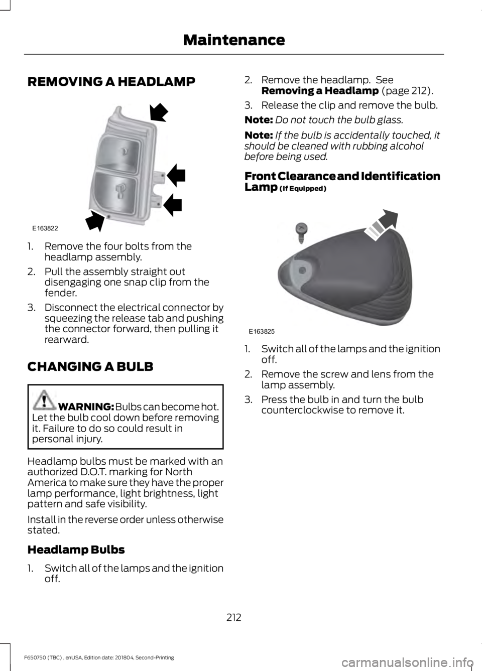
REMOVING A HEADLAMP
1. Remove the four bolts from the
headlamp assembly.
2. Pull the assembly straight out disengaging one snap clip from the
fender.
3. Disconnect the electrical connector by
squeezing the release tab and pushing
the connector forward, then pulling it
rearward.
CHANGING A BULB WARNING: Bulbs can become hot.
Let the bulb cool down before removing
it. Failure to do so could result in
personal injury.
Headlamp bulbs must be marked with an
authorized D.O.T. marking for North
America to make sure they have the proper
lamp performance, light brightness, light
pattern and safe visibility.
Install in the reverse order unless otherwise
stated.
Headlamp Bulbs
1. Switch all of the lamps and the ignition
off. 2. Remove the headlamp. See
Removing a Headlamp (page 212).
3. Release the clip and remove the bulb.
Note: Do not touch the bulb glass.
Note: If the bulb is accidentally touched, it
should be cleaned with rubbing alcohol
before being used.
Front Clearance and Identification
Lamp
(If Equipped) 1.
Switch all of the lamps and the ignition
off.
2. Remove the screw and lens from the lamp assembly.
3. Press the bulb in and turn the bulb counterclockwise to remove it.
212
F650750 (TBC) , enUSA, Edition date: 201804, Second-Printing MaintenanceE163822 E163825
Page 222 of 387
Regular fuel filter changes are an
important part of engine maintenance;
failing to keep with the scheduled
maintenance could lead to engine
performance issues and fuel injection
system damage. See Scheduled
Maintenance (page 322).
Use only recommended service parts
conforming to specifications. See
Motorcraft Parts
(page 257).
Note: Using fuel that has high levels of
impurities may require more frequent filter
replacements than the service interval
specifies.
Diesel Fuel Conditioner Module
Filter
Removal
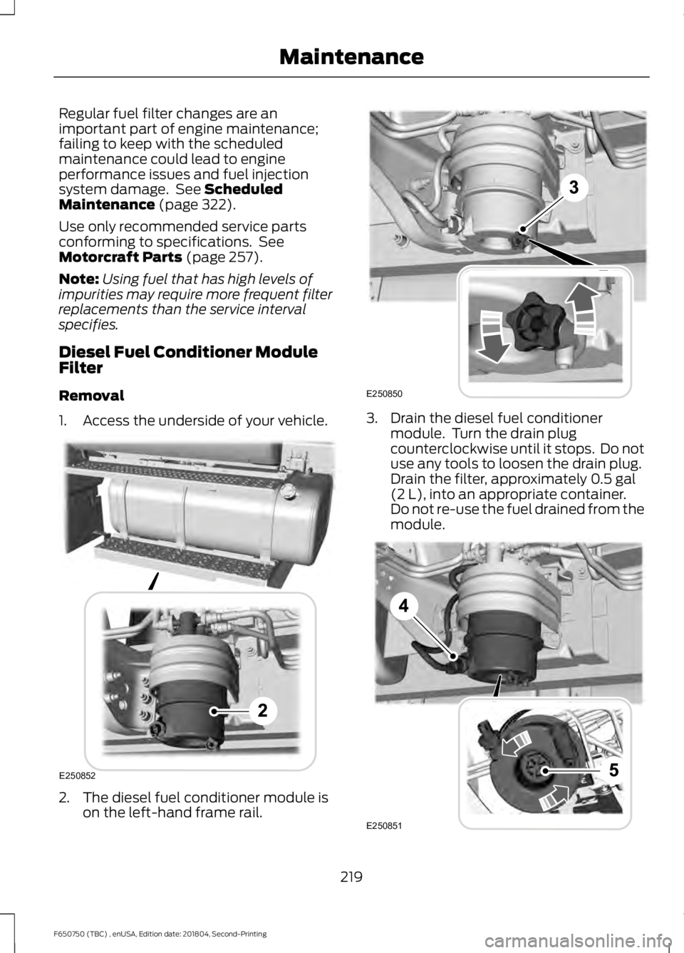
1. Access the underside of your vehicle. 2. The diesel fuel conditioner module is
on the left-hand frame rail. 3. Drain the diesel fuel conditioner
module. Turn the drain plug
counterclockwise until it stops. Do not
use any tools to loosen the drain plug.
Drain the filter, approximately
0.5 gal
(2 L), into an appropriate container.
Do not re-use the fuel drained from the
module. 219
F650750 (TBC) , enUSA, Edition date: 201804, Second-Printing MaintenanceE250852 E250850 E250851
Page 223 of 387
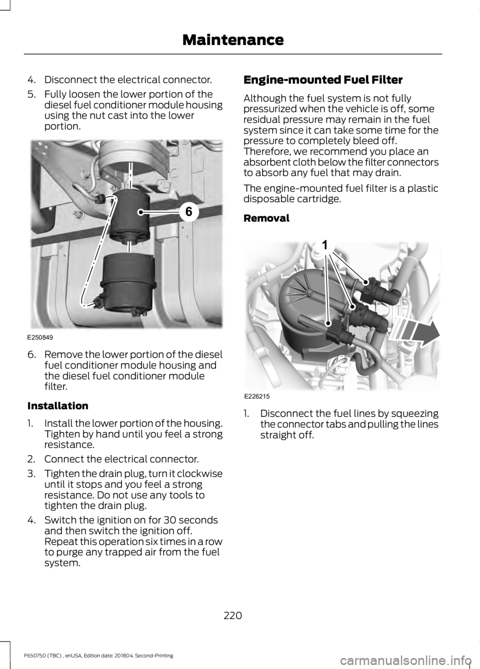
4. Disconnect the electrical connector.
5. Fully loosen the lower portion of the
diesel fuel conditioner module housing
using the nut cast into the lower
portion. 6.
Remove the lower portion of the diesel
fuel conditioner module housing and
the diesel fuel conditioner module
filter.
Installation
1. Install the lower portion of the housing.
Tighten by hand until you feel a strong
resistance.
2. Connect the electrical connector.
3. Tighten the drain plug, turn it clockwise
until it stops and you feel a strong
resistance. Do not use any tools to
tighten the drain plug.
4. Switch the ignition on for 30 seconds and then switch the ignition off.
Repeat this operation six times in a row
to purge any trapped air from the fuel
system. Engine-mounted Fuel Filter
Although the fuel system is not fully
pressurized when the vehicle is off, some
residual pressure may remain in the fuel
system since it can take some time for the
pressure to completely bleed off.
Therefore, we recommend you place an
absorbent cloth below the filter connectors
to absorb any fuel that may drain.
The engine-mounted fuel filter is a plastic
disposable cartridge.
Removal
1.
Disconnect the fuel lines by squeezing
the connector tabs and pulling the lines
straight off.
220
F650750 (TBC) , enUSA, Edition date: 201804, Second-Printing MaintenanceE250849 E226215
1
Page 224 of 387
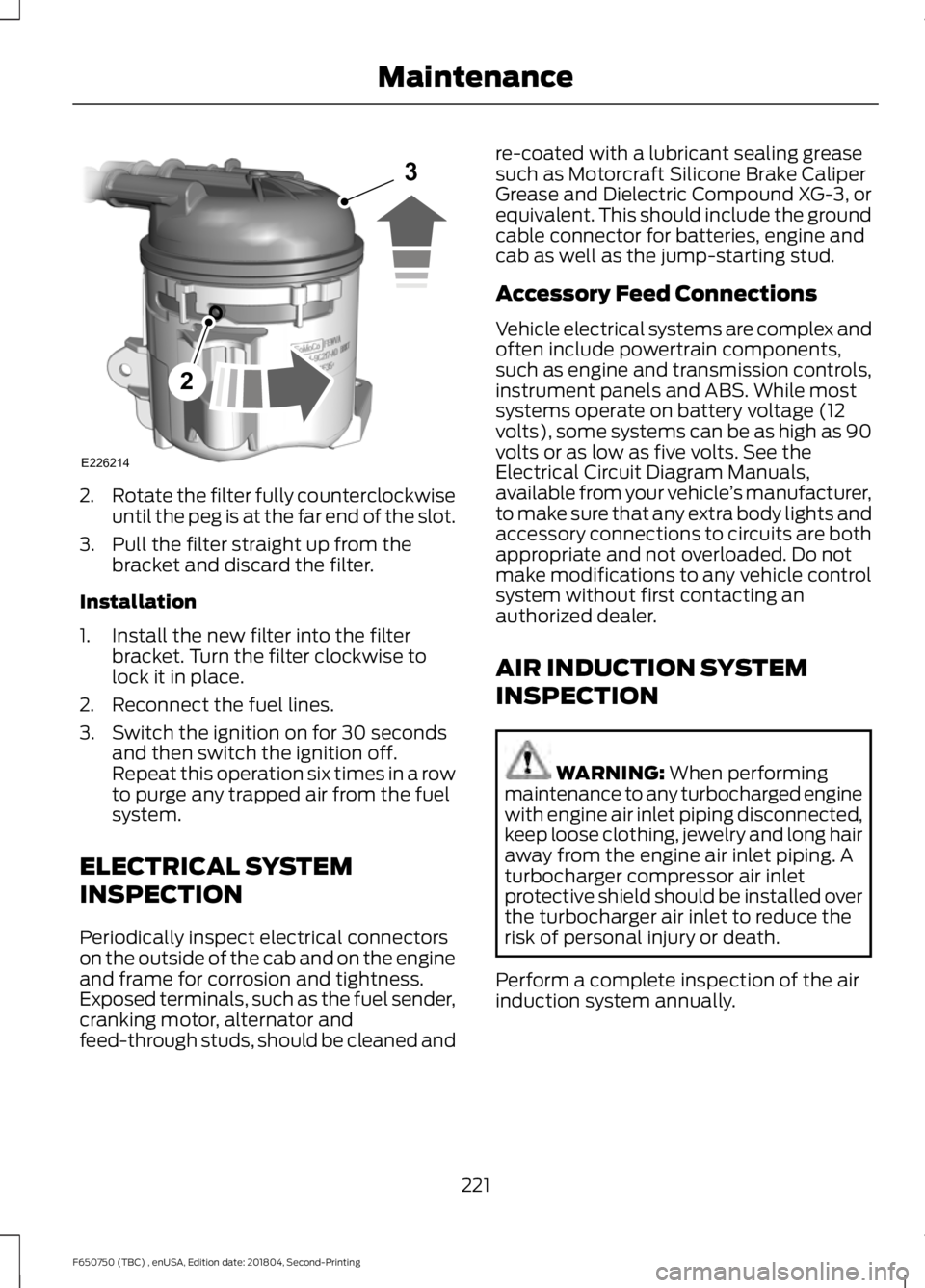
2.
Rotate the filter fully counterclockwise
until the peg is at the far end of the slot.
3. Pull the filter straight up from the bracket and discard the filter.
Installation
1. Install the new filter into the filter bracket. Turn the filter clockwise to
lock it in place.
2. Reconnect the fuel lines.
3. Switch the ignition on for 30 seconds and then switch the ignition off.
Repeat this operation six times in a row
to purge any trapped air from the fuel
system.
ELECTRICAL SYSTEM
INSPECTION
Periodically inspect electrical connectors
on the outside of the cab and on the engine
and frame for corrosion and tightness.
Exposed terminals, such as the fuel sender,
cranking motor, alternator and
feed-through studs, should be cleaned and re-coated with a lubricant sealing grease
such as Motorcraft Silicone Brake Caliper
Grease and Dielectric Compound XG-3, or
equivalent. This should include the ground
cable connector for batteries, engine and
cab as well as the jump-starting stud.
Accessory Feed Connections
Vehicle electrical systems are complex and
often include powertrain components,
such as engine and transmission controls,
instrument panels and ABS. While most
systems operate on battery voltage (12
volts), some systems can be as high as 90
volts or as low as five volts. See the
Electrical Circuit Diagram Manuals,
available from your vehicle
’s manufacturer,
to make sure that any extra body lights and
accessory connections to circuits are both
appropriate and not overloaded. Do not
make modifications to any vehicle control
system without first contacting an
authorized dealer.
AIR INDUCTION SYSTEM
INSPECTION WARNING: When performing
maintenance to any turbocharged engine
with engine air inlet piping disconnected,
keep loose clothing, jewelry and long hair
away from the engine air inlet piping. A
turbocharger compressor air inlet
protective shield should be installed over
the turbocharger air inlet to reduce the
risk of personal injury or death.
Perform a complete inspection of the air
induction system annually.
221
F650750 (TBC) , enUSA, Edition date: 201804, Second-Printing MaintenanceE226214
2
3
Page 255 of 387

WARNING: Never get underneath
a vehicle that is supported only by a jack.
If the vehicle slips off the jack, you or
someone else could be seriously injured. WARNING:
Do not attempt to
change a tire on the side of the vehicle
close to moving traffic. Pull far enough
off the road to avoid the danger of being
hit when operating the jack or changing
the wheel.
Note: Passengers should not remain in the
vehicle when the vehicle is being jacked.
Park on a level surface, set the parking
brake and activate the hazard flashers. 1.
Turn the engine off and block the wheel
that is diagonally opposite of the flat
tire using a wheel chock.
2. Loosen each wheel lug nut ½ turn counterclockwise, but do not remove
them until the wheel is raised off the
ground. 3.
Replace the flat tire with the spare tire,
making sure the valve stem is facing
outward on all front and inboard rear
wheels. If you are replacing the
outboard wheel, the valve stem must
be facing inward. Reinstall the lug nuts
until the wheel is snug against the hub.
Do not fully tighten the lug nuts until
the wheel has been lowered.
4. Lower the wheel and fully tighten the lug nuts in the order shown below. See
Technical Specifications (page 253).
5. Unblock the wheels. 8-lug nut torque sequence.
10-lug nut torque sequence.
252
F650750 (TBC) , enUSA, Edition date: 201804, Second-Printing Wheels and TiresE142551 E161441
13
4
27
6
5
8 1
2
3
4
5
6
7 8
9
10
E169375
Page 281 of 387

Always handle discs by their edges only.
Clean the disc with an approved CD
cleaner only. Wipe it from the center of
the disc toward the edge. Do not clean in
a circular motion.
Do not expose discs to direct sunlight or
heat sources for extended periods.
MP3 and WMA Track and Folder
Structure
Audio systems capable of recognizing and
playing MP3 and WMA individual tracks
and folder structures work as follows:
•
There are two different modes for MP3
and WMA disc playback: MP3 and
WMA track mode (system default) and
MP3 and WMA folder mode.
• MP3 and WMA track mode ignores any
folder structure on the MP3 and WMA
disc. The player numbers each MP3
and WMA track on the disc (noted by
the MP3 or WMA file extension) from
T001 to a maximum of T255. The
maximum number of playable MP3 and
WMA files may be less depending on
the structure of the CD and exact
model of radio present.
• MP3 and WMA folder mode represents
a folder structure consisting of one
level of folders. The CD player numbers
all MP3 and WMA tracks on the disc
(noted by the MP3 or WMA file
extension) and all folders containing
MP3 and WMA files, from F001 (folder)
T001 (track) to F253 T255.
• Creating discs with only one level of
folders helps with navigation through
the disc files.
If you are burning your own MP3 and WMA
discs, it is important to understand how
the system reads the structures you create.
While various files may be present (files
with extensions other than MP3 and
WMA), only files with the MP3 and WMA extension are played; other files are
ignored by the system. This enables you to
use the same MP3 and WMA disc for a
variety of tasks on your work computer,
home computer and your in-vehicle
system.
In track mode, the system displays and
plays the structure as if it were only one
level deep (all MP3 and WMA files play,
regardless of being in a specific folder). In
folder mode, the system only plays the
MP3 and WMA files in the current folder.
AUDIO UNIT - VEHICLES WITH:
AM/FM
WARNING: Driving while
distracted can result in loss of vehicle
control, crash and injury. We strongly
recommend that you use extreme
caution when using any device that may
take your focus off the road. Your
primary responsibility is the safe
operation of your vehicle. We
recommend against the use of any
hand-held device while driving and
encourage the use of voice-operated
systems when possible. Make sure you
are aware of all applicable local laws
that may affect the use of electronic
devices while driving.
Accessing the Clock Settings Press and release to display the
clock.
To set the time, press and hold until the
hours start to flash. Use the center arrow
controls to change the hours, then repeat
to set the minutes. Press again to exit clock
mode.
278
F650750 (TBC) , enUSA, Edition date: 201804, Second-Printing Audio SystemE265935
Page 283 of 387
Accessing CD or MP3 Mode
Press and release the button.
Accessing the Folders Press and release the buttons to
access the next and previous
folders on an MP3 disc.
Accessing the Menu Press and release to access
different audio system features.
• To set the clock, press MENU until SET
HOURS or SET MINUTES appears
and use the up and down arrow to
adjust the time.
• To set the strongest stations on the
radio frequency, press
MENU until
AUTOSET appears. This does not
override your original presets.
• RBDS
displays text transmitted by
certain radio stations and searches
for music categories.
• When
RBDS ON/OFF appears, press
SEEK to switch on RBDS to search for
music categories. Press the up and
down arrow to scroll through
categories, then press
SEEK to begin
the search.
• SPEEDVOL
allows you to adjust
radio volume to compensate for
noise levels when vehicle speed
increases. •
Track/Folder is only available on MP3
files when in CD mode. In track mode,
press
SEEK to scroll through all the
tracks on the disc. In folder mode, press
SEEK
to scroll through all the tracks
within the selected folder. Press
FOLDER
to access other folders.
• COMPRESS
is only available in CD
and MP3 modes. Switching on
compression brings the soft and
loud passages together for a more
consistent listening level.
• To switch compression on and off,
press
SEEK and the up and down
arrow.
Accessing the Phone Features Press and release to access the
phone features of the SYNC
system.
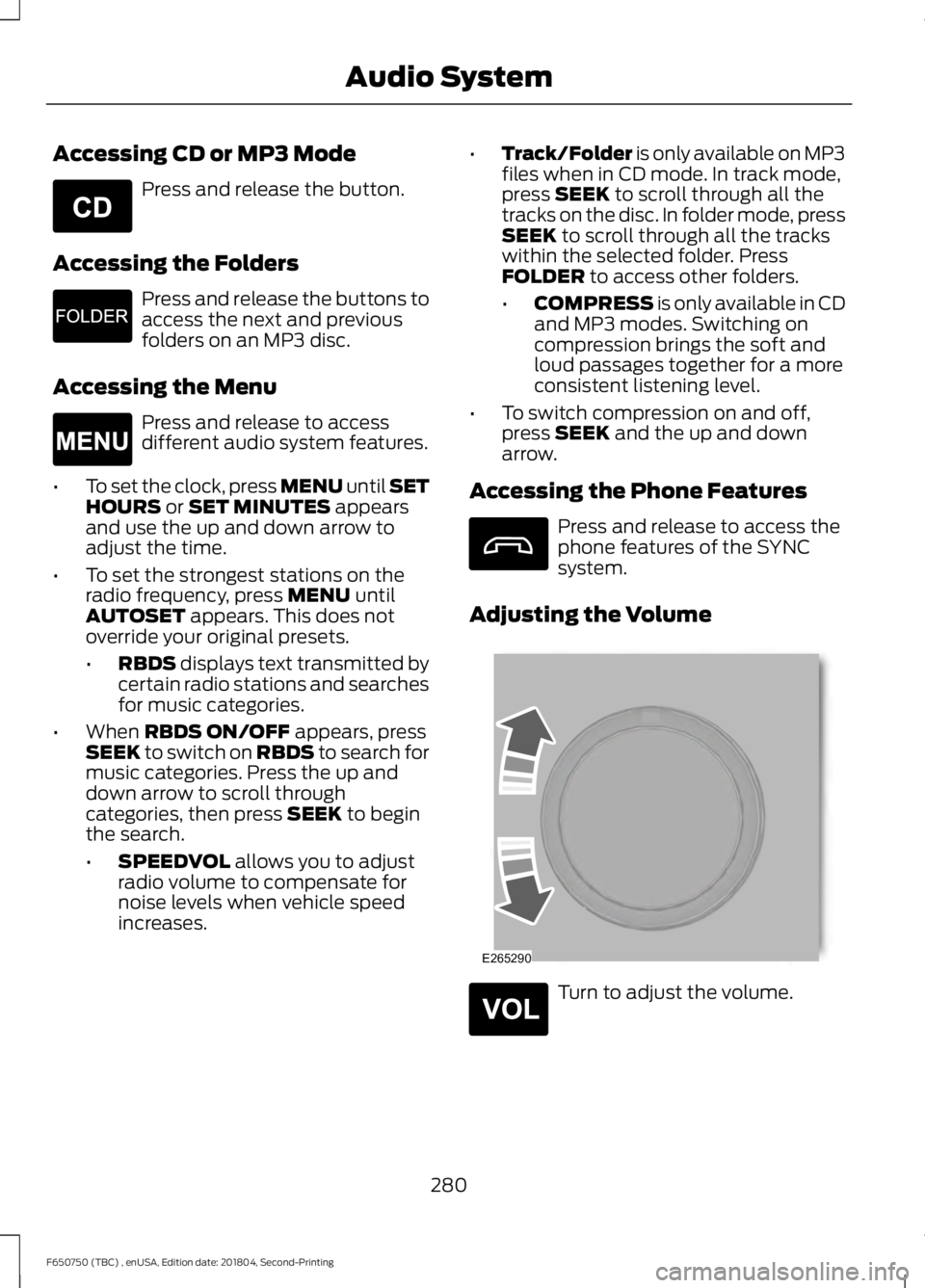
Adjusting the Volume Turn to adjust the volume.
280
F650750 (TBC) , enUSA, Edition date: 201804, Second-Printing Audio SystemE265039 E265913 E265038 E265290 E265304