2019 FORD F-450 warning light
[x] Cancel search: warning lightPage 259 of 666

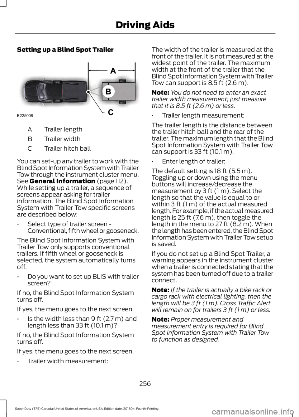
Setting up a Blind Spot Trailer
Trailer length
A
Trailer width
B
Trailer hitch ball
C
You can set-up any trailer to work with the
Blind Spot Information System with Trailer
Tow through the instrument cluster menu.
See General Information (page 112).
While setting up a trailer, a sequence of
screens appear asking for trailer
information. The Blind Spot Information
System with Trailer Tow specific screens
are described below:
• Select type of trailer screen -
Conventional, fifth wheel or gooseneck.
The Blind Spot Information System with
Trailer Tow only supports conventional
trailers. If fifth wheel or gooseneck is
selected, the system automatically turns
off.
• Do you want to set up BLIS with trailer
screen?
If no, the Blind Spot Information System
turns off.
If yes, the menu goes to the next screen.
• Is the width less than
9 ft (2.7 m) and
length less than 33 ft (10.1 m)?
If no, the Blind Spot Information System
turns off.
If yes, the menu goes to the next screen.
• Trailer width measurement: The width of the trailer is measured at the
front of the trailer. It is not measured at the
widest point of the trailer. The maximum
width at the front of the trailer that the
Blind Spot Information System with Trailer
Tow can support is
8.5 ft (2.6 m).
Note: You do not need to enter an exact
trailer width measurement; just measure
that it is
8.5 ft (2.6 m) or less.
• Trailer length measurement:
The trailer length is the distance between
the trailer hitch ball and the rear of the
trailer. The maximum length that the Blind
Spot Information System with Trailer Tow
can support is
33 ft (10.1 m).
• Enter length of trailer:
The default setting is
18 ft (5.5 m).
Toggling up or down using the menu
buttons will increase/decrease the
measurement by
3 ft (1 m). Select the
length so that the value is equal to or
within
3 ft (1 m) of the actual measured
length. For example, if the actual measured
length is
25 ft (7.6 m), then toggle the
length in the menu to 27 ft (8.2 m). When
the length has been entered, the Blind Spot
Information System with Trailer Tow setup
is saved.
If you do not set up a Blind Spot Trailer, a
warning appears in the instrument cluster
when a trailer is connected stating that the
system has been turned off due to a trailer
connect.
Note: If the trailer is actually a bike rack or
cargo rack with electrical lighting, then the
length will be
3 ft (1 m). Cross Traffic Alert
will remain on for trailers 3 ft (1 m) or less.
Note: Proper measurement and
measurement entry is required for Blind
Spot Information System with Trailer Tow
to function as designed.
256
Super Duty (TFE) Canada/United States of America, enUSA, Edition date: 201804, Fourth-Printing Driving AidsE225008
Page 266 of 666

WARNING: This system is an extra
driving aid. It does not replace your
attention and judgment, or the need to
apply the brakes. This system does NOT
automatically brake your vehicle. If you
fail to press the brake pedal when
necessary, you may collide with another
vehicle. WARNING: The Pre-Collision
Assist system with brake support cannot
help prevent all collisions. Do not rely on
this system to replace your judgment
and the need to maintain correct
distance and speed. WARNING: The pre-collision assist
system's brake support reduces collision
speed only if you brake your vehicle
before any collision. You must press your
brake pedal as you would in any typical
braking situation.
Note: The system does not detect, warn or
respond to potential collisions with vehicles
to the rear or side of your vehicle.
Note: The system is active at speeds above
approximately
5 mph (8 km/h).
Note: The system becomes unavailable if
you disable the electronic stability control.
See
Using Stability Control (page 229). The system is designed to alert the driver
of certain collision risks. A radar detects if
your vehicle is rapidly approaching another
vehicle traveling in the same direction as
yours. When your vehicle rapidly approaches
another vehicle, a red warning light
illuminates and an audible warning tone
sounds.
The brake support system assists the driver
in reducing the collision speed by charging
the brakes. If the risk of collision further
increases after the warning light
illuminates, the brake support prepares
the brake system for rapid braking. This
may be apparent to the driver. Brake
support does not automatically apply the
brakes. If you press the brake pedal, the
system could apply additional braking up
to maximum braking force, even if you
lightly press the brake pedal.
Using the System
You can use your information display
control to adjust the system's sensitivity
or to switch the system on or off. Your
vehicle remembers the settings across key
cycles. You may change the system
sensitivity to any one of three possible
settings.
See General Information (page
112).
Note: We recommend that you switch the
system off if you install a snow plow or
similar object in such a way that it may
block the radar sensor. Your vehicle
remembers the selected setting across key
cycles.
263
Super Duty (TFE) Canada/United States of America, enUSA, Edition date: 201804, Fourth-Printing Driving AidsE156130 E156131
Page 286 of 666

Note:
In some cases, if vehicle speed is too
high, the system may activate multiple
times, gradually reducing vehicle speed.
This feature applies your vehicle brakes at
individual wheels and, if necessary, reduces
engine power. If the trailer begins to sway,
the stability control light flashes and the
message TRAILER SWAY REDUCE
SPEED appears in the information display.
The first thing to do is slow your vehicle
down, then pull safely to the side of the
road and check for proper tongue load and
trailer load distribution. See
Load
Carrying (page 266).
RECOMMENDED TOWING
WEIGHTS WARNING:
You must use
the heavy-duty drawbar pin
supplied with your vehicle when
using the heavy-duty hitch.
Failure to follow this instruction
could result in the loss of control
of your vehicle, personal injury or
death.
Note: Vehicles with a heavy-duty
hitch must use the drawbar pin
stamped 21,000 LBS. You can
obtain a replacement drawbar pin
at your authorized dealer. Note:
Make sure to take into
consideration trailer frontal area.
Do not exceed 60 ft 2
(5.6 m 2
) trailer
frontal area for conventional
trailers. Do not exceed 75 ft 2
(6.9
m 2
) trailer frontal area for fifth
wheel and gooseneck trailers.
Note: Exceeding this limitation
may significantly reduce the
performance of your towing
vehicle. Selecting a trailer with a
low aerodynamic drag and rounded
front design helps optimize
performance and fuel economy.
Note: For high altitude operation,
reduce the gross combined weight
by 2% per 1,000 ft (300 m)
starting at the 1,000 ft (300 m)
elevation point.
Note: Certain states require
electric trailer brakes for trailers
over a specified weight. Be sure to
check state regulations for this
specified weight. The maximum
trailer weights listed may be limited
to this specified weight, as your
vehicle's electrical system may not
include the wiring connector
needed to use electric trailer
brakes.
Your vehicle may tow a trailer
provided the maximum trailer
weight is less than or equal to the
maximum trailer weight
calculated using the formula
following the chart.
283
Super Duty (TFE) Canada/United States of America, enUSA, Edition date: 201804, Fourth-Printing Towing
Page 290 of 666

ESSENTIAL TOWING CHECKS
WARNING: Do not exceed the
maximum vertical load on the tow ball.
Failure to follow this instruction could
result in the loss of control of your
vehicle, personal injury or death.
Follow these guidelines for safe towing:
• Do not tow a trailer until you drive your
vehicle at least
1,000 mi (1,600 km).
• Consult your local motor vehicle laws
for towing a trailer.
• See the instructions included with
towing accessories for the proper
installation and adjustment
specifications.
• Service your vehicle more frequently if
you tow a trailer. See your scheduled
maintenance information.
See
Scheduled Maintenance (page 580).
• If you use a rental trailer, follow the
instructions the rental agency gives
you.
See
Load Limits in the Load Carrying
chapter for load specification terms found
on the tire label and Safety Compliance
label and instructions on calculating your
vehicle's load.
Vehicles with a diesel engine have an
engine braking feature.
See General
Information (page 223).
Remember to account for the trailer
tongue weight as part of your vehicle load
when calculating the total vehicle weight.
Some vehicles will have the ability to
modify trailer towing features. See
General Information
(page 112). Trailer Towing Connector
When attaching the trailer wiring connector
to your vehicle, only use a proper fitting
connector that works with the vehicle and
trailer functions. Some seven-position
connectors may have the SAE J2863 logo,
which confirms that it is the proper wiring
connector and works correctly with your
vehicle.
Function
Color
Left turn signal and stop lamp
Yellow
Ground (-)
White
Electric brakes
Blue
Right turn signal and stop
lamp
Green
Battery (+)
Orange
Running lights
Brown
Reverse lights
Grey
287
Super Duty (TFE) Canada/United States of America, enUSA, Edition date: 201804, Fourth-Printing TowingE163167
Page 293 of 666

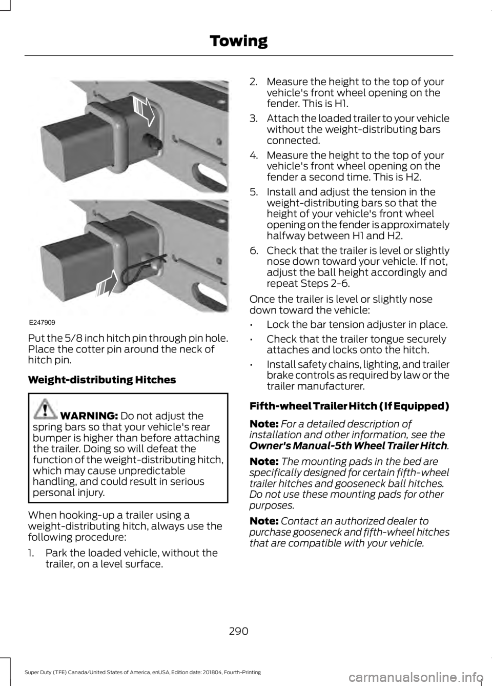
Put the 5/8 inch hitch pin through pin hole.
Place the cotter pin around the neck of
hitch pin.
Weight-distributing Hitches
WARNING: Do not adjust the
spring bars so that your vehicle's rear
bumper is higher than before attaching
the trailer. Doing so will defeat the
function of the weight-distributing hitch,
which may cause unpredictable
handling, and could result in serious
personal injury.
When hooking-up a trailer using a
weight-distributing hitch, always use the
following procedure:
1. Park the loaded vehicle, without the trailer, on a level surface. 2. Measure the height to the top of your
vehicle's front wheel opening on the
fender. This is H1.
3. Attach the loaded trailer to your vehicle
without the weight-distributing bars
connected.
4. Measure the height to the top of your vehicle's front wheel opening on the
fender a second time. This is H2.
5. Install and adjust the tension in the weight-distributing bars so that the
height of your vehicle's front wheel
opening on the fender is approximately
halfway between H1 and H2.
6. Check that the trailer is level or slightly
nose down toward your vehicle. If not,
adjust the ball height accordingly and
repeat Steps 2-6.
Once the trailer is level or slightly nose
down toward the vehicle:
• Lock the bar tension adjuster in place.
• Check that the trailer tongue securely
attaches and locks onto the hitch.
• Install safety chains, lighting, and trailer
brake controls as required by law or the
trailer manufacturer.
Fifth-wheel Trailer Hitch (If Equipped)
Note: For a detailed description of
installation and other information, see the
Owner's Manual-5th Wheel Trailer Hitch.
Note: The mounting pads in the bed are
specifically designed for certain fifth-wheel
trailer hitches and gooseneck ball hitches.
Do not use these mounting pads for other
purposes.
Note: Contact an authorized dealer to
purchase gooseneck and fifth-wheel hitches
that are compatible with your vehicle.
290
Super Duty (TFE) Canada/United States of America, enUSA, Edition date: 201804, Fourth-Printing TowingE247909
Page 295 of 666

Integrated Trailer Brake Controller
(If Equipped)
WARNING: The anti-lock brake
system does not control the trailer
brakes. WARNING:
Use the integrated
trailer brake controller to properly adjust
the trailer brakes and check all
connections before towing a trailer.
Failure to follow this instruction could
result in the loss of control of your
vehicle, personal injury or death.
Note: The integrated Ford brake controller
is compatible with trailers equipped with
electric-actuated drum brakes and
electric-over hydraulic brake systems.
Note: The integrated Ford brake controller
does not control hydraulic surge-style
brakes. When used properly, the trailer brake
controller assists in smooth and effective
trailer braking by powering the trailer
’s
electric or electric-over-hydraulic brakes
with a proportional output based on the
towing vehicle ’s brake pressure.
You can adjust the amount of initial trailer
brake output by selecting one of three
settings through the message center. Ford has tested the trailer brake controller
to be compatible with several major
brands of electric-over-hydraulic trailer
brakes. Contact an authorized dealer for
information on which brands you can use.
The controller user interface consists of
the following:
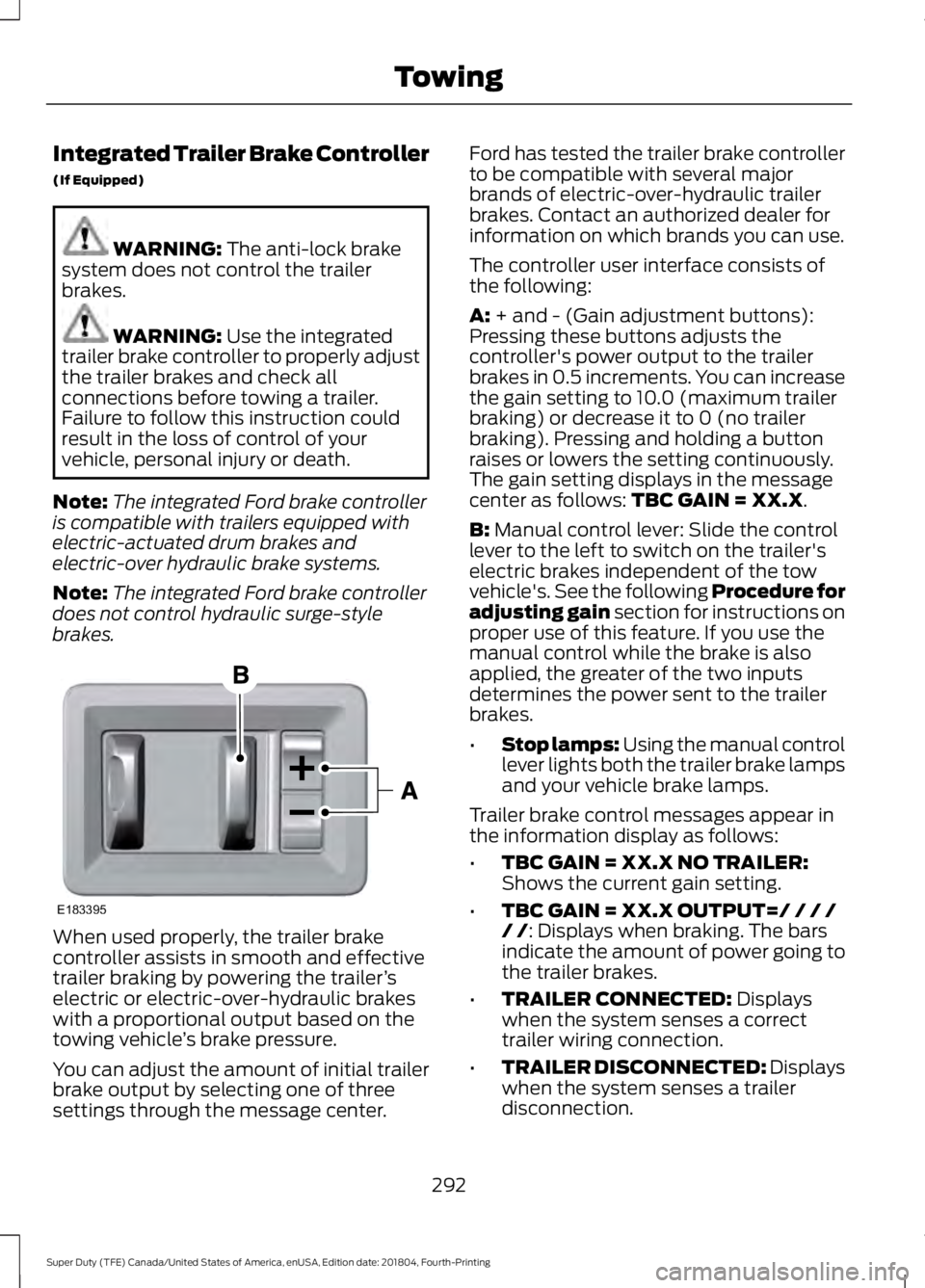
A: + and - (Gain adjustment buttons):
Pressing these buttons adjusts the
controller's power output to the trailer
brakes in 0.5 increments. You can increase
the gain setting to 10.0 (maximum trailer
braking) or decrease it to 0 (no trailer
braking). Pressing and holding a button
raises or lowers the setting continuously.
The gain setting displays in the message
center as follows:
TBC GAIN = XX.X.
B:
Manual control lever: Slide the control
lever to the left to switch on the trailer's
electric brakes independent of the tow
vehicle's. See the following Procedure for
adjusting gain section for instructions on
proper use of this feature. If you use the
manual control while the brake is also
applied, the greater of the two inputs
determines the power sent to the trailer
brakes.
• Stop lamps: Using the manual control
lever lights both the trailer brake lamps
and your vehicle brake lamps.
Trailer brake control messages appear in
the information display as follows:
• TBC GAIN = XX.X NO TRAILER:
Shows the current gain setting.
• TBC GAIN = XX.X OUTPUT=/ / / /
/ /
: Displays when braking. The bars
indicate the amount of power going to
the trailer brakes.
• TRAILER CONNECTED:
Displays
when the system senses a correct
trailer wiring connection.
• TRAILER DISCONNECTED: Displays
when the system senses a trailer
disconnection.
292
Super Duty (TFE) Canada/United States of America, enUSA, Edition date: 201804, Fourth-Printing TowingE183395
Page 297 of 666

If this message displays, with no trailer
connected, the problem is with your vehicle
wiring or trailer brake controller. Contact
an authorized dealer.
If the message only displays with a trailer
connected, the problem is with the trailer
wiring. Consult your trailer dealer for
assistance. This can be a short to ground
(such as a chaffed wire), short to voltage
(such as a pulled pin on trailer emergency
breakaway battery) or the trailer brakes
may be drawing too much current.
Points to Remember
Note:
Do not attempt removal of the trailer
brake controller without consulting the
Workshop Manual. Damage to the unit may
result.
• Adjust gain setting before using the
trailer brake controller.
• Adjust gain setting, using the procedure
above, whenever road, weather, trailer
or vehicle loading conditions change
from when the gain was initially set.
• Only use the manual control lever for
proper adjustment of the gain during
trailer setup. Misuse, such as
application during trailer sway, could
cause instability of trailer or tow
vehicle.
• Avoid towing in adverse weather
conditions. The trailer brake controller
does not provide anti-lock control of
the trailer wheels. Trailer wheels can
lock up on slippery surfaces, resulting
in reduced stability of trailer and tow
vehicle.
• The trailer brake controller is equipped
with a feature that reduces output at
vehicle speeds below 11 mph (18 km/h)
so trailer and vehicle braking is not jerky
or harsh. This feature is only active
when applying the brakes using your
vehicle's brake pedal, not the
controller. •
The controller interacts with the brake
control system and powertrain control
system of your vehicle to provide the
best performance on different road
conditions.
• Your vehicle's brake system and the
trailer brake system work
independently of each other. Changing
the gain setting on the controller does
not affect the operation of your
vehicle's brakes.
• When you switch the engine off, the
controller output is disabled and the
display and module shut down.
Trailer Lamps WARNING: Never connect any
trailer lamp wiring to the vehicle's tail
lamp wiring; this may damage the
electrical system resulting in fire. Contact
your authorized dealer as soon as
possible for assistance in proper trailer
tow wiring installation. Additional
electrical equipment may be required.
Trailer lamps are required on most towed
vehicles. Make sure all running lights, brake
lights, turn signals and hazard lights are
working.
Before Towing a Trailer
Practice turning, stopping and backing up
to get the feel of your vehicle-trailer
combination before starting on a trip.
When turning, make wider turns so the
trailer wheels clear curbs and other
obstacles.
294
Super Duty (TFE) Canada/United States of America, enUSA, Edition date: 201804, Fourth-Printing Towing
Page 303 of 666

•
Fuel economy may decrease with lower
temperatures during the first 5–10 mi
(12 –16 km) of driving.
• Driving on flat terrain offers improved
fuel economy as compared to driving
on hilly terrain.
• Transmissions give their best fuel
economy when operated in the top
cruise gear and with steady pressure
on the gas pedal.
• Four-wheel-drive operation (if
equipped) is less fuel efficient than
two-wheel-drive operation.
• Close the windows for high-speed
driving.
DRIVING THROUGH WATER WARNING:
Do not drive through
flowing or deep water as you may lose
control of your vehicle.
Note: Driving through standing water can
cause vehicle damage.
Note: Engine damage can occur if water
enters the air filter.
Before driving through standing water,
check the depth. Never drive through water
that is higher than the bottom of the wheel
hubs. When driving through standing water, drive
very slowly and do not stop your vehicle.
Your brake performance and traction may
be limited. After driving through water and
as soon as it is safe to do so:
•
Lightly press the brake pedal to dry the
brakes and to check that they work.
• Check that the horn works.
• Check that the exterior lights work.
• Turn the steering wheel to check that
the steering power assist works.
FLOOR MATS WARNING:
Use a floor mat
designed to fit the footwell of your
vehicle that does not obstruct the pedal
area. Failure to follow this instruction
could result in the loss of control of your
vehicle, personal injury or death. WARNING:
Pedals that cannot
move freely can cause loss of vehicle
control and increase the risk of serious
personal injury. WARNING:
Secure the floor mat
to both retention devices so that it
cannot slip out of position and interfere
with the pedals. Failure to follow this
instruction could result in the loss of
control of your vehicle, personal injury or
death. WARNING:
Do not place
additional floor mats or any other
covering on top of the original floor mats.
This could result in the floor mat
interfering with the operation of the
pedals. Failure to follow this instruction
could result in the loss of control of your
vehicle, personal injury or death.
300
Super Duty (TFE) Canada/United States of America, enUSA, Edition date: 201804, Fourth-Printing Driving HintsE176913