2019 FORD EXPEDITION light
[x] Cancel search: lightPage 301 of 583
between the trailer brake controller and
the 7-pin connector at the bumper. If the
message only displays with a trailer
connected, the problem is with the trailer
wiring. Consult your trailer dealer for
assistance. This can be a short to ground
such as a chaffed wire, short to voltage
such as a pulled pin on trailer emergency
breakaway battery, or the trailer brakes
may be drawing too much current.
Points to Remember
Note:
Do not attempt removal of the trailer
brake controller without consulting the
Workshop Manual. Damage to the unit may
result.
• Adjust gain setting before using the
trailer brake controller for the first time.
• Adjust gain setting, using the procedure
above, whenever road, weather and
trailer or vehicle loading conditions
change from when the gain was initially
set.
• Only use the manual control lever for
proper adjustment of the gain during
trailer setup. Misuse, such as
application during trailer sway, could
cause instability of trailer or tow
vehicle.
• Avoid towing in adverse weather
conditions. The trailer brake controller
does not provide anti-lock control of
the trailer wheels. Trailer wheels can
lock up on slippery surfaces, resulting
in reduced stability of trailer and tow
vehicle.
• The trailer brake controller is equipped
with a feature that reduces output at
vehicle speeds below 11 mph (18 km/h)
so trailer and vehicle braking is not jerky
or harsh. This feature is only available
when applying the brakes using your
vehicle's brake pedal, not the
controller. •
The controller interacts with the brake
control system and powertrain control
system of your vehicle to provide the
best performance on different road
conditions.
• Your vehicle's brake system and the
trailer brake system work
independently of each other. Changing
the gain setting on the controller does
not affect the operation of your
vehicle's brakes whether you attach a
trailer or not.
• When you switch the engine off, the
controller output is disabled and the
display and module shut down. The
controller module and display turn on
when you switch the ignition on.
• The trailer brake controller is only a
factory-installed or dealer-installed
item. Ford is not responsible for
warranty or performance of the
controller due to misuse or customer
installation.
Trailer Lamps WARNING: Never connect any
trailer lamp wiring to the vehicle's tail
lamp wiring; this may damage the
electrical system resulting in fire. Contact
your authorized dealer as soon as
possible for assistance in proper trailer
tow wiring installation. Additional
electrical equipment may be required.
Trailer lamps are required on most towed
vehicles. Make sure all running lights, brake
lights, direction indicators and hazard lights
are working.
298
Expedition (TB8) Canada/United States of America, enUSA, Edition date: 201808, Second-Printing Towing
Page 305 of 583
Note:
If your vehicle has intelligent access,
you can keep the vehicle on when switching
the engine off by pressing the
START/STOP button two times slowly
without pressing the brake pedal.
3. Press and hold the brake pedal.
4. Shift the transmission out of neutral (N) and into park (P).
5. Release the brake pedal.
Note: If completed successfully, the
instrument cluster displays
4X2, and
Neutral Tow Disabled.
Note: If the indicator light and message do
not display, you must perform the procedure
again from the beginning.
Note: You may hear an audible noise as the
transfer case shifts out of its neutral
position. This is normal.
Note: If
Shift Delayed Pull Forward
appears in the instrument cluster, transfer
case gear tooth blockage is present. See the
instructions after this section.
6. Apply the parking brake, then disconnect your vehicle from the tow
vehicle.
7. Release the parking brake, start the engine and shift the transmission to
drive (D) to make sure the transfer
case is out neutral (N).
8. If the transfer case does not successfully shift out of neutral (N),
set the parking brake until you can have
your vehicle serviced.
Resolving the
Shift Delayed Pull
Forward Message
If the instrument cluster displays
Shift
Delayed Pull Forward, perform the
following:
1. Press and hold the brake pedal.
2. Put the transmission into neutral (N), then start the engine. 3. With the engine running, shift the
transmission to drive (D) and let the
vehicle roll forward up to
3 ft (1 m). You
may hear an audible noise as the
transfer case shifts out of its neutral
position. This is normal.
4. Make sure the instrument cluster displays
Neutral Tow Disabled.
302
Expedition (TB8) Canada/United States of America, enUSA, Edition date: 201808, Second-Printing Towing
Page 307 of 583
•
Do not warm up your vehicle on cold
mornings.
• Reduce the use of air conditioning and
heat.
• Avoid using speed control in hilly
terrain.
• Do not rest your foot on the brake
pedal while driving.
• Avoid carrying unnecessary weight.
• Avoid adding particular accessories to
your vehicle (e.g. bug deflectors,
rollbars/light bars, running boards, ski
racks).
• Avoid driving with the wheels out of
alignment.
DRIVING THROUGH WATER WARNING: Do not drive through
flowing or deep water as you may lose
control of your vehicle.
Note: Driving through standing water can
cause vehicle damage.
Note: Engine damage can occur if water
enters the air filter.
Before driving through standing water,
check the depth. Never drive through water
that is higher than the bottom of the wheel
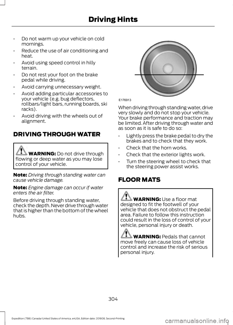
hubs. When driving through standing water, drive
very slowly and do not stop your vehicle.
Your brake performance and traction may
be limited. After driving through water and
as soon as it is safe to do so:
•
Lightly press the brake pedal to dry the
brakes and to check that they work.
• Check that the horn works.
• Check that the exterior lights work.
• Turn the steering wheel to check that
the steering power assist works.
FLOOR MATS WARNING:
Use a floor mat
designed to fit the footwell of your
vehicle that does not obstruct the pedal
area. Failure to follow this instruction
could result in the loss of control of your
vehicle, personal injury or death. WARNING:
Pedals that cannot
move freely can cause loss of vehicle
control and increase the risk of serious
personal injury.
304
Expedition (TB8) Canada/United States of America, enUSA, Edition date: 201808, Second-Printing Driving HintsE176913
Page 311 of 583
4. You can attempt to start the vehicle
by pressing the brake pedal and
START/STOP, or press START/STOP
without pressing the brake pedal.
5. If the vehicle does not start, repeat steps 1 through 4.
JUMP STARTING THE VEHICLE WARNING:
Batteries normally
produce explosive gases which can
cause personal injury. Therefore, do not
allow flames, sparks or lighted
substances to come near the battery.
When working near the battery, always
shield your face and protect your eyes.
Always provide correct ventilation. WARNING:
Keep batteries out of
reach of children. Batteries contain
sulfuric acid. Avoid contact with skin,
eyes or clothing. Shield your eyes when
working near the battery to protect
against possible splashing of acid
solution. In case of acid contact with skin
or eyes, flush immediately with water for
a minimum of 15 minutes and get prompt
medical attention. If acid is swallowed,
call a physician immediately. WARNING:
Use only adequately
sized cables with insulated clamps.
Note: To avoid reverse polarity connections,
make sure that you correctly identify the
positive (+) and negative (-) terminals on
both the disabled and booster vehicles
before connecting the cables. Stay clear of
moving parts.
Preparing Your Vehicle
Do not attempt to push-start your
automatic transmission vehicle. Note:
Attempting to push-start a vehicle
with an automatic transmission may cause
transmission damage.
Note: Use only a 12-volt supply to start your
vehicle.
Note: Do not disconnect the battery of the
disabled vehicle as this could damage the
vehicle electrical system.
Park the booster vehicle close to the hood
of the disabled vehicle, making sure the
two vehicles do not touch.
Connecting the Jumper Cables WARNING:
Do not use fuel lines,
engine valve covers, windshield wiper
arms, the intake manifold, or hood latch
as ground points. WARNING:
Do not connect the
end of the second cable to the negative
(-) terminal of the battery to be jumped.
A spark may cause an explosion of the
gases that surround the battery.
Note: Do not attach the end of the positive
cable to the studs or L-shaped eyelet
located above the positive (+) terminal of
your vehicle ’s battery. High current may flow
through and cause damage to the fuses.
Note: In the illustration, the bottom vehicle
represents the booster vehicle.
308
Expedition (TB8) Canada/United States of America, enUSA, Edition date: 201808, Second-Printing Roadside Emergencies
Page 326 of 583
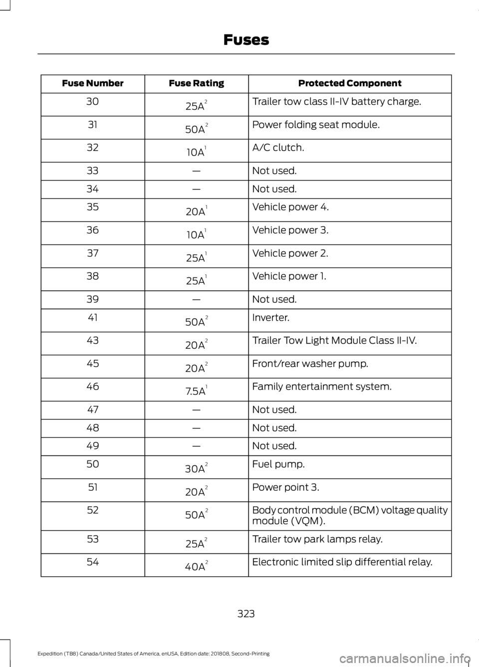
Protected Component
Fuse Rating
Fuse Number
Trailer tow class II-IV battery charge.
25A 2
30
Power folding seat module.
50A 2
31
A/C clutch.
10A 1
32
Not used.
—
33
Not used.
—
34
Vehicle power 4.
20A 1
35
Vehicle power 3.
10A 1
36
Vehicle power 2.
25A 1
37
Vehicle power 1.
25A 1
38
Not used.
—
39
Inverter.
50A 2
41
Trailer Tow Light Module Class II-IV.
20A 2
43
Front/rear washer pump.
20A 2
45
Family entertainment system.
7.5A 1
46
Not used.
—
47
Not used.
—
48
Not used.
—
49
Fuel pump.
30A 2
50
Power point 3.
20A 2
51
Body control module (BCM) voltage quality
module (VQM).
50A 2
52
Trailer tow park lamps relay.
25A 2
53
Electronic limited slip differential relay.
40A 2
54
323
Expedition (TB8) Canada/United States of America, enUSA, Edition date: 201808, Second-Printing Fuses
Page 338 of 583
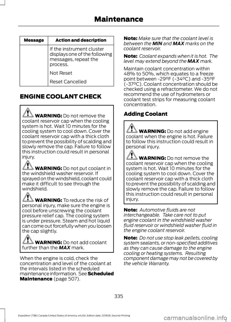
Action and description
Message
If the instrument cluster
displays one of the following
messages, repeat the
process.
Not Reset
Reset Cancelled
ENGINE COOLANT CHECK WARNING: Do not remove the
coolant reservoir cap when the cooling
system is hot. Wait 10 minutes for the
cooling system to cool down. Cover the
coolant reservoir cap with a thick cloth
to prevent the possibility of scalding and
slowly remove the cap. Failure to follow
this instruction could result in personal
injury. WARNING:
Do not put coolant in
the windshield washer reservoir. If
sprayed on the windshield, coolant could
make it difficult to see through the
windshield. WARNING:
To reduce the risk of
personal injury, make sure the engine is
cool before unscrewing the coolant
pressure relief cap. The cooling system
is under pressure. Steam and hot liquid
can come out forcefully when you loosen
the cap slightly. WARNING:
Do not add coolant
further than the MAX mark.
When the engine is cold, check the
concentration and level of the coolant at
the intervals listed in the scheduled
maintenance information. See Scheduled
Maintenance
(page 507). Note:
Make sure that the coolant level is
between the
MIN and MAX marks on the
coolant reservoir.
Note: Coolant expands when it is hot. The
level may extend beyond the
MAX mark.
Maintain coolant concentration within
48% to 50%, which equates to a freeze
point between
-29°F (-34°C) and -35°F
(-37°C). Coolant concentration should be
checked using a refractometer. We do not
recommend the use of hydrometers or
coolant test strips for measuring coolant
concentration.
Adding Coolant WARNING:
Do not add engine
coolant when the engine is hot. Failure
to follow this instruction could result in
personal injury. WARNING:
Do not remove the
coolant reservoir cap when the cooling
system is hot. Wait 10 minutes for the
cooling system to cool down. Cover the
coolant reservoir cap with a thick cloth
to prevent the possibility of scalding and
slowly remove the cap. Failure to follow
this instruction could result in personal
injury.
Note: Automotive fluids are not
interchangeable. Take care not to put
engine coolant in the windshield washer
fluid reservoir or windshield washer fluid in
the engine coolant reservoir.
Note: Do not use stop leak pellets, cooling
system sealants, or non-specified additives
as they can cause damage to the engine
cooling or heating systems. Resulting
component damage may not be covered by
the vehicle Warranty.
335
Expedition (TB8) Canada/United States of America, enUSA, Edition date: 201808, Second-Printing Maintenance
Page 344 of 583
State or local regulations on volatile
organic compounds may restrict the use
of methanol, a common windshield washer
antifreeze additive. Washer fluids
containing non-methanol antifreeze
agents should be used only if they provide
cold weather protection without damaging
the vehicle
’s paint finish, wiper blades or
washer system.
FUEL FILTER
Your vehicle is equipped with a lifetime
fuel filter that is integrated with the fuel
tank. Regular maintenance or replacement
is not needed.
CHANGING THE 12V BATTERY WARNING: Batteries normally
produce explosive gases which can
cause personal injury. Therefore, do not
allow flames, sparks or lighted
substances to come near the battery.
When working near the battery, always
shield your face and protect your eyes.
Always provide correct ventilation. WARNING:
When lifting a
plastic-cased battery, excessive pressure
on the end walls could cause acid to flow
through the vent caps, resulting in
personal injury and damage to the
vehicle or battery. Lift the battery with a
battery carrier or with your hands on
opposite corners. WARNING:
Keep batteries out of
reach of children. Batteries contain
sulfuric acid. Avoid contact with skin,
eyes or clothing. Shield your eyes when
working near the battery to protect
against possible splashing of acid
solution. In case of acid contact with skin
or eyes, flush immediately with water for
a minimum of 15 minutes and get prompt
medical attention. If acid is swallowed,
call a physician immediately. WARNING:
Battery posts,
terminals and related accessories
contain lead and lead compounds,
chemicals known to the State of
California to cause cancer and
reproductive harm. Wash your hands
after handling
. WARNING: This vehicle may have
more than one battery. Removing the
battery cables from only one battery
does not disconnect your vehicle
electrical system. Make sure you
disconnect the battery cables from all
batteries when disconnecting power.
Failure to do so may cause serious
personal injury or property damage.
Your vehicle is fitted with a Motorcraft
maintenance-free battery which normally
does not require additional water.
When a battery replacement is required,
you must use a recommended
replacement battery that matches the
electrical requirements of the vehicle.
Note: After cleaning or replacing the
battery, make sure you reinstall the battery
vent tube, battery cover or shield.
For longer, trouble-free operation, keep the
top of the battery clean and dry.
341
Expedition (TB8) Canada/United States of America, enUSA, Edition date: 201808, Second-Printing Maintenance
Page 347 of 583
3. Press the wiper blade secondary
locking clip.
4. Remove the wiper blade.
Note: Make sure that the wiper arm does
not spring back against the glass when the
wiper blade is not attached.
5. Install in the reverse order.
Note: Make sure that the wiper blade locks
into place.
ADJUSTING THE HEADLAMPS
Vertical Aim Adjustment
The headlamps on your vehicle are
properly aimed at the assembly plant. If
your vehicle has been in an accident,
contact an authorized dealer to check and
realign your headlamps.
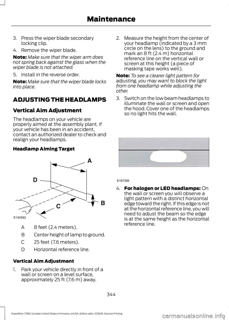
Headlamp Aiming Target 8 feet (2.4 meters).
A
Center height of lamp to ground.
B
25 feet (7.6 meters).
C
Horizontal reference line.
D
Vertical Aim Adjustment
1. Park your vehicle directly in front of a wall or screen on a level surface,
approximately 25 ft (7.6 m) away. 2. Measure the height from the center of
your headlamp (indicated by a 3 mm
circle on the lens) to the ground and
mark an
8 ft (2.4 m) horizontal
reference line on the vertical wall or
screen at this height (a piece of
masking tape works well).
Note: To see a clearer light pattern for
adjusting, you may want to block the light
from one headlamp while adjusting the
other.
3. Switch on the low beam headlamps to
illuminate the wall or screen and open
the hood. Cover one of the headlamps
so no light hits the wall. 4.
For halogen or LED headlamps:
On
the wall or screen you will observe a
light pattern with a distinct horizontal
edge toward the right. If this edge is not
at the horizontal reference line, you will
need to adjust the beam so the edge
is at the same height as the horizontal
reference line.
344
Expedition (TB8) Canada/United States of America, enUSA, Edition date: 201808, Second-Printing MaintenanceE142592 E167358