2019 FORD EXPEDITION light
[x] Cancel search: lightPage 263 of 583
Zone coverage also decreases when
parking at narrow angles. The sensor on
the left-hand side is mostly obstructed and
zone coverage on that side is severely
reduced.
System Lights, Messages and
Audible Alerts
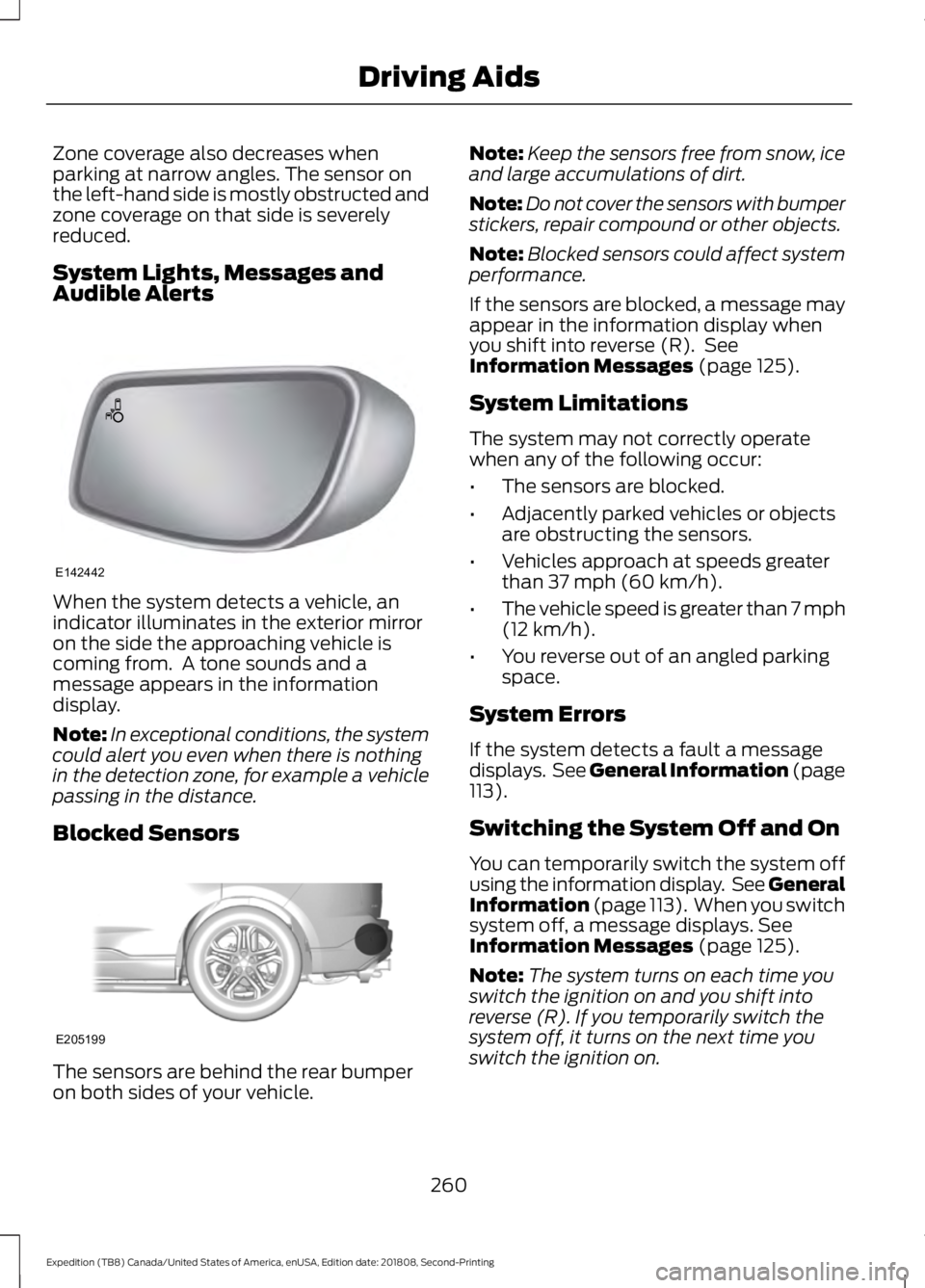
When the system detects a vehicle, an
indicator illuminates in the exterior mirror
on the side the approaching vehicle is
coming from. A tone sounds and a
message appears in the information
display.
Note:
In exceptional conditions, the system
could alert you even when there is nothing
in the detection zone, for example a vehicle
passing in the distance.
Blocked Sensors The sensors are behind the rear bumper
on both sides of your vehicle. Note:
Keep the sensors free from snow, ice
and large accumulations of dirt.
Note: Do not cover the sensors with bumper
stickers, repair compound or other objects.
Note: Blocked sensors could affect system
performance.
If the sensors are blocked, a message may
appear in the information display when
you shift into reverse (R). See
Information Messages (page 125).
System Limitations
The system may not correctly operate
when any of the following occur:
• The sensors are blocked.
• Adjacently parked vehicles or objects
are obstructing the sensors.
• Vehicles approach at speeds greater
than
37 mph (60 km/h).
• The vehicle speed is greater than 7 mph
(12 km/h)
.
• You reverse out of an angled parking
space.
System Errors
If the system detects a fault a message
displays. See General Information (page
113
).
Switching the System Off and On
You can temporarily switch the system off
using the information display. See
General
Information (page 113). When you switch
system off, a message displays. See
Information Messages (page 125).
Note: The system turns on each time you
switch the ignition on and you shift into
reverse (R). If you temporarily switch the
system off, it turns on the next time you
switch the ignition on.
260
Expedition (TB8) Canada/United States of America, enUSA, Edition date: 201808, Second-Printing Driving AidsE142442 E205199
Page 265 of 583
PRE-COLLISION ASSIST (IF
EQUIPPED) WARNING:
You are responsible
for controlling your vehicle at all times.
The system is designed to be an aid and
does not relieve you of your responsibility
to drive with due care and attention.
Failure to follow this instruction could
result in the loss of control of your
vehicle, personal injury or death. WARNING:
The system does not
detect vehicles that are driving in a
different direction, cyclists or animals.
Failure to take care may result in the loss
of control of your vehicle, serious
personal injury or death. WARNING:
The system does not
operate during hard acceleration or
steering. Failure to take care may lead
to a crash or personal injury. WARNING:
The system may fail
or operate with reduced function during
cold and severe weather conditions.
Snow, ice, rain, spray and fog can
adversely affect the system. Keep the
front camera and radar free of snow and
ice. Failure to take care may result in the
loss of control of your vehicle, serious
personal injury or death. WARNING: In situations where the
vehicle camera has limited detection
capability, this may reduce system
performance. These situations include
but are not limited to direct or low
sunlight, vehicles at night without tail
lights, unconventional vehicle types,
pedestrians with complex backgrounds, partly obscured pedestrians, or
pedestrians that the system cannot
distinguish from a group. Failure to take
care may result in the loss of control of
your vehicle, serious personal injury or
death.
WARNING:
The system cannot
help prevent all crashes. Do not rely on
this system to replace driver judgment
and the need to maintain a safe distance
and speed.
Using the Pre-Collision Assist
System
The Pre-Collision Assist system is active
at speeds above approximately
3 mph
(5 km/h) and pedestrian detection is active
at speeds up to
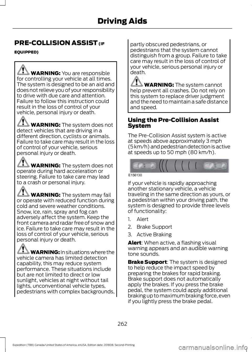
50 mph (80 km/h). If your vehicle is rapidly approaching
another stationary vehicle, a vehicle
traveling in the same direction as yours, or
a pedestrian within your driving path, the
system is designed to provide three levels
of functionality:
1. Alert
2. Brake Support
3. Active Braking
Alert
: When active, a flashing visual
warning appears and an audible warning
tone sounds.
Brake Support
: The system is designed
to help reduce the impact speed by
preparing the brakes for rapid braking.
Brake support does not automatically
apply the brakes. If you press the brake
pedal, the system could apply additional
braking up to maximum braking force, even
if you lightly press the brake pedal.
262
Expedition (TB8) Canada/United States of America, enUSA, Edition date: 201808, Second-Printing Driving AidsE156130
Page 274 of 583
For the short wheel base system, it is
necessary for the second panel located
toward the front of the vehicle to be raised
up when the seats are folded down.
For the long wheel base system, it is
necessary for the second panel located
toward the front of the vehicle to be raised
up.
Note:
Before moving the board into the
shelf position, you may need to flip down
the hooks.
Note: Do not put more than 50 lb (22 kg)
on shelf.
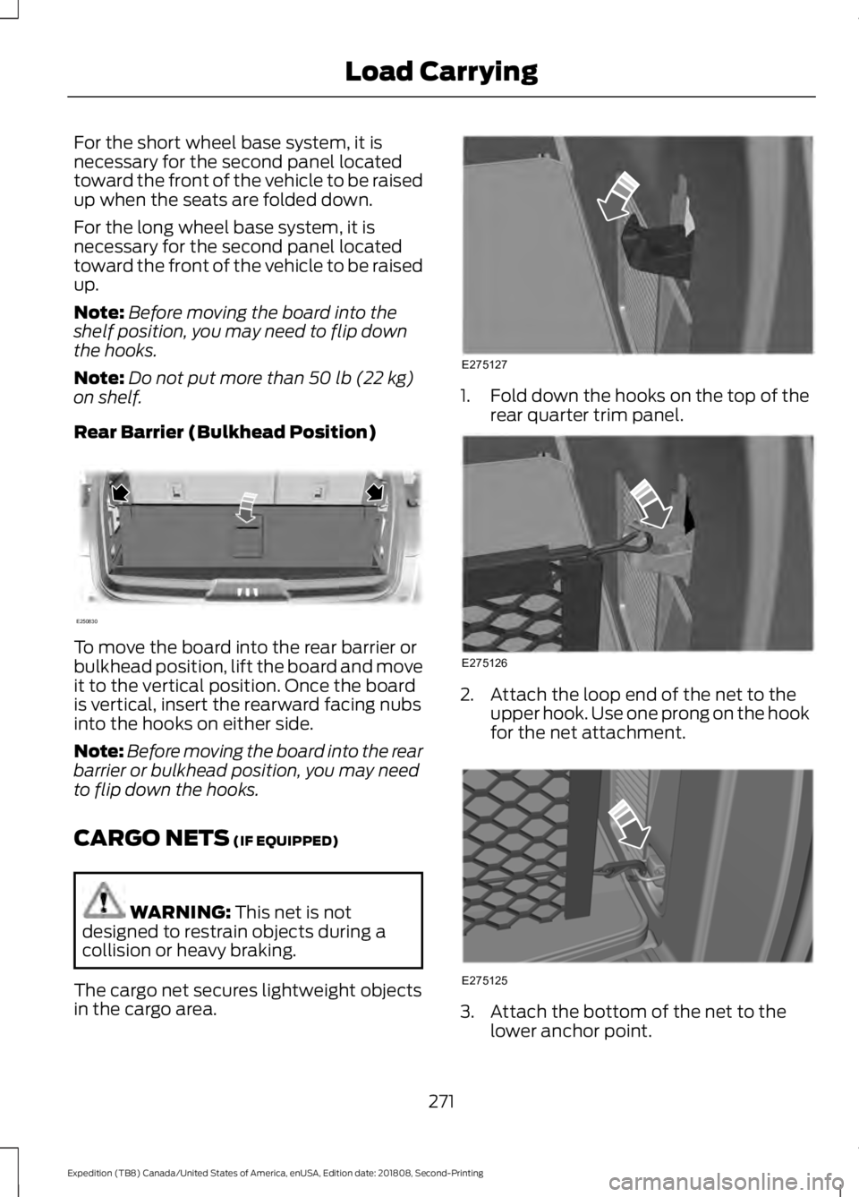
Rear Barrier (Bulkhead Position) To move the board into the rear barrier or
bulkhead position, lift the board and move
it to the vertical position. Once the board
is vertical, insert the rearward facing nubs
into the hooks on either side.
Note:
Before moving the board into the rear
barrier or bulkhead position, you may need
to flip down the hooks.
CARGO NETS
(IF EQUIPPED) WARNING:
This net is not
designed to restrain objects during a
collision or heavy braking.
The cargo net secures lightweight objects
in the cargo area. 1.
Fold down the hooks on the top of the
rear quarter trim panel. 2. Attach the loop end of the net to the
upper hook. Use one prong on the hook
for the net attachment. 3. Attach the bottom of the net to the
lower anchor point.
271
Expedition (TB8) Canada/United States of America, enUSA, Edition date: 201808, Second-Printing Load CarryingE250830 E275127 E275126 E275125
Page 282 of 583

TOWING A TRAILER
WARNING: Towing trailers
beyond the maximum
recommended gross trailer
weight exceeds the limit of your
vehicle and could result in engine
damage, transmission damage,
structural damage, loss of
vehicle control, vehicle rollover
and personal injury. WARNING:
Do not exceed
the GVWR or the GAWR
specified on the certification
label.
Your vehicle may have electrical
items, such as fuses or relays,
related to towing. See
Fuses
(page 320).
Some vehicles may have the
ability to modify trailer towing
features. See Towing (page 279).
Your vehicle's load capacity
designation is by weight, not by
volume, so you cannot necessarily
use all available space when
loading a vehicle or trailer.
Towing a trailer places an extra
load on your vehicle's engine,
transmission, axle, brakes, tires
and suspension. Inspect these
components periodically during,
and after, any towing operation. Load Placement
To help minimize how trailer
movement affects your vehicle
when driving:
•
Load the heaviest items closest
to the trailer floor.
• Load the heaviest items
centered between the left and
right side trailer tires.
• Load the heaviest items above
the trailer axles or just slightly
forward toward the trailer
tongue. Do not allow the final
trailer tongue weight to go
above or below 10-15% of the
loaded trailer weight.
• Select a ball mount with the
correct rise or drop and load
capacity. When both the
loaded vehicle and trailer are
connected, the trailer frame
should be level, or slightly
angled down toward your
vehicle, when viewed from the
side.
When driving with a trailer or
payload, a slight takeoff vibration
or shudder may be present due to
the increased payload weight.
Additional information regarding
proper trailer loading and setting
your vehicle up for towing is
located in another chapter of this
manual. See
Load Limit (page
273).
You can also find information in
the
RV & Trailer Towing Guide
available at your authorized
dealer, or online.
279
Expedition (TB8) Canada/United States of America, enUSA, Edition date: 201808, Second-Printing Towing
Page 290 of 583
For best results:
•
Use a long, straight, smooth and level
road when attempting to calibrate.
• Drive straight forward.
• Drive between 4 mph (6 km/h) and
24 mph (39 km/h).
System Operation
The following warnings or difficulties may
occur during feature operation. Tips to
resolve them are listed below.
The system is not available:
• The system relies on many
sub-systems in your vehicle to operate
correctly. If those sub-systems are not
operating correctly the system may not
be available.
• Low battery voltage is a condition
which prevents the system from
operating. Please make sure the
battery is correctly charged if the
system is not available.
• You may need to drive your vehicle
straight forward above
25 mph
(40 km/h) before the system is
available again.
• If the message still displays take your
vehicle to an authorized dealer for
service.
Sticker lost:
• If the system cannot initially find the
sticker, it may be necessary for you to
change the lighting conditions by
moving the vehicle and trailer or
waiting until conditions change.
• Check for the following if you receive
the lost sticker message while using
the system.
• Stop your vehicle as soon as the
message displays.
• Make sure the sticker is visible and the
pattern is discernable in the rear view
camera image. •
Clean the sticker and camera to make
sure they are unobstructed.
• Clean the lens with a soft, lint-free
cloth and water.
• Clean the sticker with isopropyl rubbing
alcohol sprayed directly onto the
sticker, and then wipe clean with a soft
cloth.
• Remove any items that may be
blocking the view of the sticker.
Depending on your trailer configuration
and any equipment mounted to your
trailer it is possible for the sticker to be
blocked from view of the camera as it
rotates on the hitch ball but not be
blocked during setup. Remove the
obstruction if possible. It is necessary
to remove the sticker from its current
location if the obstruction cannot be
cleared and place a new sticker that is
visible to the camera in all positions of
the trailer behind your vehicle.
• Placing the sticker on a surface angled
away from the vehicle reduces
performance. Use a drawbar that
positions the trailer level to the ground
when attached to vehicle. This typically
provides a level surface to mount the
sticker. Place the sticker on a bracket
or other object when no level surface
is available.
• Make sure the entire sticker is on a flat
surface that is completely visible to the
camera. Do not fold the sticker over an
edge on the trailer frame. This can
degrade performance.
• Shadows on the sticker may effect
tracking performance under some
lighting conditions. Moving the sticker
to another location within the allowed
placement area may improve
performance. Use the change sticker
option in your Towing menu if you
move the sticker.
287
Expedition (TB8) Canada/United States of America, enUSA, Edition date: 201808, Second-Printing Towing
Page 293 of 583
This feature applies your vehicle brakes at
individual wheels and, if necessary, reduces
engine power. If the trailer begins to sway,
the stability control light flashes and the
message TRAILER SWAY REDUCE
SPEED appears in the information display.
The first thing to do is slow your vehicle
down, then pull safely to the side of the
road and check for proper tongue load and
trailer load distribution. See Towing (page
279
).
RECOMMENDED TOWING
WEIGHTS
Note: Do not exceed the trailer
weight for your vehicle
configuration listed in the chart
below.
Note: Make sure to take into
consideration trailer frontal area.
Do not exceed 36.5 feet² (3.39
meters²) if your vehicle is equipped
with the standard towing package,
or 60 feet² (5.57 meters²) if your
vehicle is equipped with the
optional heavy duty package.
Note: Exceeding this limitation
may significantly reduce the
performance of your towing
vehicle. Selecting a trailer with a
low aerodynamic drag and rounded
front design helps optimize
performance and fuel economy.
Note: For high altitude operation,
reduce the gross combined weight
by 2% per
1,000 ft (300 m)
starting at the 1,000 ft (300 m)
elevation point. Note:
Certain states require
electric trailer brakes for trailers
over a specified weight. Be sure to
check state regulations for this
specified weight. The maximum
trailer weights listed may be limited
to this specified weight, as the
vehicle ’s electrical system may not
include the wiring connector
needed to activate electric trailer
brakes.
Your vehicle may tow a trailer
provided the maximum trailer
weight is less than or equal to the
maximum trailer weight listed for
your vehicle configuration on the
following chart.
To calculate the maximum loaded
trailer weight for your vehicle:
1. Start with the gross combined weight rating for your vehicle
model and axle ratio. See the
following chart.
2. Subtract all of the following
that apply to your vehicle:
•Vehicle curb weight.
• Hitch hardware weight, such
as a draw bar, ball, locks or
weight distributing.
• Driver weight.
• Passenger weight.
• Payload, cargo and luggage
weight.
• Aftermarket equipment
weight.
3. This equals the maximum
loaded trailer weight for this
combination.
290
Expedition (TB8) Canada/United States of America, enUSA, Edition date: 201808, Second-Printing Towing
Page 296 of 583
ESSENTIAL TOWING CHECKS
Follow these guidelines for safe towing:
•
Do not tow a trailer until you drive your
vehicle at least 1,000 mi (1,600 km).
• Consult your local motor vehicle laws
for towing a trailer.
• See the instructions included with
towing accessories for the proper
installation and adjustment
specifications.
• Service your vehicle more frequently if
you tow a trailer. See your scheduled
maintenance information.
• If you use a rental trailer, follow the
instructions the rental agency gives
you.
For load specification terms found on the
tire label and Safety Compliance label and
instructions on calculating your vehicle's
load,
See Load Limit (page 273).
Remember to account for the trailer
tongue weight as part of your vehicle load
when calculating the total vehicle weight.
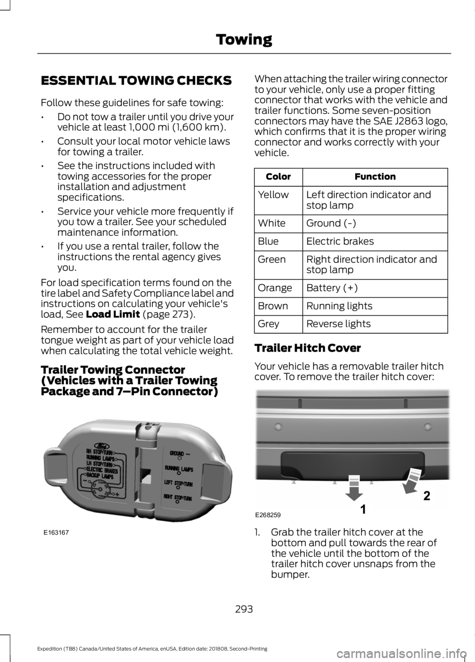
Trailer Towing Connector
(Vehicles with a Trailer Towing
Package and 7 –Pin Connector) When attaching the trailer wiring connector
to your vehicle, only use a proper fitting
connector that works with the vehicle and
trailer functions. Some seven-position
connectors may have the SAE J2863 logo,
which confirms that it is the proper wiring
connector and works correctly with your
vehicle.
Function
Color
Left direction indicator and
stop lamp
Yellow
Ground (-)
White
Electric brakes
Blue
Right direction indicator and
stop lamp
Green
Battery (+)
Orange
Running lights
Brown
Reverse lights
Grey
Trailer Hitch Cover
Your vehicle has a removable trailer hitch
cover. To remove the trailer hitch cover: 1. Grab the trailer hitch cover at the
bottom and pull towards the rear of
the vehicle until the bottom of the
trailer hitch cover unsnaps from the
bumper.
293
Expedition (TB8) Canada/United States of America, enUSA, Edition date: 201808, Second-Printing TowingE163167 E268259
Page 298 of 583
Weight-distributing Hitch
WARNING: Do not adjust the
spring bars so that your vehicle's rear
bumper is higher than before attaching
the trailer. Doing so will defeat the
function of the weight-distributing hitch,
which may cause unpredictable
handling, and could result in serious
personal injury.
When hooking-up a trailer using a
weight-distributing hitch, always use the
following procedure:
1. Park the loaded vehicle, without the trailer, on a level surface.
2. Measure the height to the top of your vehicle's front wheel opening on the
fender. This is H1.
3. Attach the loaded trailer to your vehicle
without the weight-distributing bars
connected.
4. Measure the height to the top of your vehicle's front wheel opening on the
fender a second time. This is H2.
5. Install and adjust the tension in the weight-distributing bars so that the
height of your vehicle's front wheel
opening on the fender is approximately
half the way down from H2, toward H1.
6. Check that the trailer is level or slightly
nose down toward your vehicle. If not,
adjust the ball height accordingly and
repeat steps 2-6.
When the trailer is level or slightly nose
down toward the vehicle:
• Lock the bar tension adjuster in place.
• Check that the trailer tongue securely
attaches and locks onto the hitch.
• Install safety chains, lighting, and trailer
brake controls as required by law or the
trailer manufacturer. Safety Chains
Note:
Do not attach safety chains to the
bumper. Always connect the safety chains
to the frame or hook retainers of your trailer
hitch.
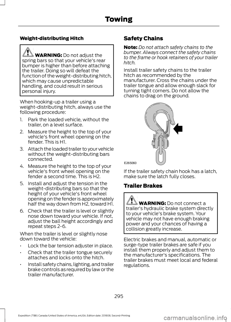
Install trailer safety chains to the trailer
hitch as recommended by the
manufacturer. Cross the chains under the
trailer tongue and allow enough slack for
turning tight corners. Do not allow the
chains to drag on the ground. If the trailer safety chain hook has a latch,
make sure the latch fully closes.
Trailer Brakes
WARNING:
Do not connect a
trailer's hydraulic brake system directly
to your vehicle's brake system. Your
vehicle may not have enough braking
power and your chances of having a
collision greatly increase.
Electric brakes and manual, automatic or
surge-type trailer brakes are safe if you
install them properly and adjust them to
the manufacturer's specifications. The
trailer brakes must meet local and federal
regulations.
295
Expedition (TB8) Canada/United States of America, enUSA, Edition date: 201808, Second-Printing TowingE265060