Page 167 of 300

few moments until the icon and message turn off. Refer to
“Instrument Cluster Display” in “Getting To Know Your
Instrument Panel” for further information.
If the Steering icon, and the�SERVICE POWER STEERING
- ASSIST OFF� messages are displayed on the instrument
cluster screen, the vehicle needs to be taken to an autho-
rized dealer for service. Refer to “Instrument Cluster
Display” in “Getting To Know Your Instrument Panel” for
further information.
NOTE:
• Even if the power steering assistance is no longer
operational, it is still possible to steer the vehicle. Under
these conditions there will be a substantial increase in
steering effort, especially at low speeds and during
parking maneuvers.
• If the condition persists, see an authorized dealer for
service.
SPEED CONTROL
When engaged, the Speed Control takes over accelerator
operations at speeds greater than 25 mph (40 km/h).
The Speed Control buttons are located on the right side of
the steering wheel. NOTE:
In order to ensure proper operation, the Speed
Control system has been designed to shut down if multiple
Speed Control functions are operated at the same time. If
this occurs, the Speed Control system can be reactivated by
pushing the Speed Control ON/OFF button and resetting
the desired vehicle set speed.
Speed Control Buttons
1 — ON/OFF 3 — SET (-)/Decel
2 — RES (+)/Resume/Accel 4 — CANC/Cancel
6
STARTING AND OPERATING 165
Page 183 of 300

IN CASE OF EMERGENCY
CONTENTS
�HAZARD WARNING FLASHERS ............182
� BULB REPLACEMENT ....................182
▫ Replacement Bulbs .....................182
▫ Replacing Exterior Bulbs ..................184
▫ Replacing Interior Bulbs ..................186
� FUSES ............................... .186
▫ Interior Fuses ......................... .187
▫ Power Distribution Center #1 ..............190
▫ Power Distribution Center #2 ..............193
� TIRE SERVICE KIT — IF EQUIPPED ..........194
▫ Tire Service Kit Storage ...................194
▫ Tire Service Kit Components And Operation . . .195
▫ Tire Service Kit Usage Precautions ..........196▫
Sealing A Tire With Tire Service Kit .........197
� JUMP STARTING PROCEDURE (12 VOLT BATTERY
ONLY)............................... .202
▫ Preparations For Jump Start ...............202
▫ Jump Starting Procedure ..................203
� MANUAL PARK RELEASE .................205
� FREEING A STUCK VEHICLE ..............206
� TOWING A DISABLED VEHICLE ............207
� ENHANCED ACCIDENT RESPONSE SYSTEM
(EARS) .............................. .208
� EVENT DATA RECORDER (EDR) ............208
7
Page 184 of 300
HAZARD WARNING FLASHERS
The Hazard Warning flasher switch is located on the
instrument panel below the radio.Push the switch to turn on the Hazard Warning
flashers. When the switch is activated, all direc-
tional turn signals will flash on and off to warn
oncoming traffic of an emergency. Push the
switch a second time to turn off the Hazard Warning
flashers. Do not use this emergency warning system when the
vehicle is in motion. Use it when your vehicle is disabled
and it is creating a safety hazard for other motorists.
If it is necessary to leave the vehicle to go for service, the
Hazard Warning flashers will continue to operate with the
ignition key removed and the vehicle locked.
NOTE:
With extended use, the Hazard Warning flashers
may wear down your battery.
BULB REPLACEMENT
Replacement Bulbs
Interior Bulbs
Bulb Number
Overhead Lamp C5W
Courtesy Lamp W5W
Rear Cargo Lamps W5W
182 IN CASE OF EMERGENCY
Page 185 of 300
Exterior Bulbs
Bulb Number
Front Low and High Beam Headlamp HIR2LL
Front Parking/Daytime Running Lamps W21/5W
Front Fog Lamps H11LL
Front Side Marker Lamps W3W
Front Turn Signal Lamps WY21W
Side Direction Lamps WY5W
Rear Turn Signal Lamps PY21W
Rear Side Marker Lamps W3W
Rear Tail and Stop Lamps P21/5W
Rear Backup Lamps W16W
Center High Mounted Stop Lamp LED (See authorized dealer)
License Plate Lamps LED (See authorized dealer)
NOTE: Numbers refer to commercial bulb types that can be purchased from an authorized dealer.
If a bulb needs to be replaced, visit an authorized dealer or refer to the applicable Service Manual.
7
IN CASE OF EMERGENCY 183
Page 188 of 300

Replacing Interior Bulbs
Rear Cargo Lamp
1. Using a suitable tool open the light box.
2. Pull the bulb out.
3. Replace the bulb, and reinstall the light box cover.
FUSES
WARNING!
•When replacing a blown fuse, always use an appro-
priate replacement fuse with the same amp rating as
the original fuse. Never replace a fuse with another
fuse of higher amp rating. Never replace a blown
fuse with metal wires or any other material. Do not
place a fuse inside a circuit breaker cavity or vice
versa. Failure to use proper fuses may result in
serious personal injury, fire and/or property damage.
• Before replacing a fuse, make sure that the ignition is
off and that all the other services are switched off
and/or disengaged.
(Continued)
WARNING! (Continued)
•If the replaced fuse blows again, contact an autho-
rized dealer.
• If a general protection fuse for safety systems (air
bag system, braking system), power unit systems
(engine system, transmission system) or steering
system blows, contact an authorized dealer.
186 IN CASE OF EMERGENCY
Page 196 of 300
CavityCartridge FuseDescription
FPT3 25 Amp WhiteBattery Coolant Pump
FPT5 20 Amp Lt. BlueInverter Coolant Pump
FPT6 40 Amp GreenSupply for fuses F9, F13, F16, F17 and
F20
TIRE SERVICE KIT — IF EQUIPPED
Small punctures up to 1/4 inch (6 mm) in the tire tread can
be sealed with Tire Service Kit. Foreign objects (e.g., screws
or nails) should not be removed from the tire. Tire Service
Kit can be used in outside temperatures down to approxi-
mately -4°F (-20°C).
This kit will provide a temporary tire seal, allowing you to
drive your vehicle up to 100 miles (160 km) with a
maximum speed of 50 mph (80 km/h).
Tire Service Kit Storage
The Tire Service Kit is located in the rear cargo area.Tire Service Kit Location
194 IN CASE OF EMERGENCY
Page 197 of 300

Tire Service Kit Components And OperationUsing The Mode Select Knob And Hoses
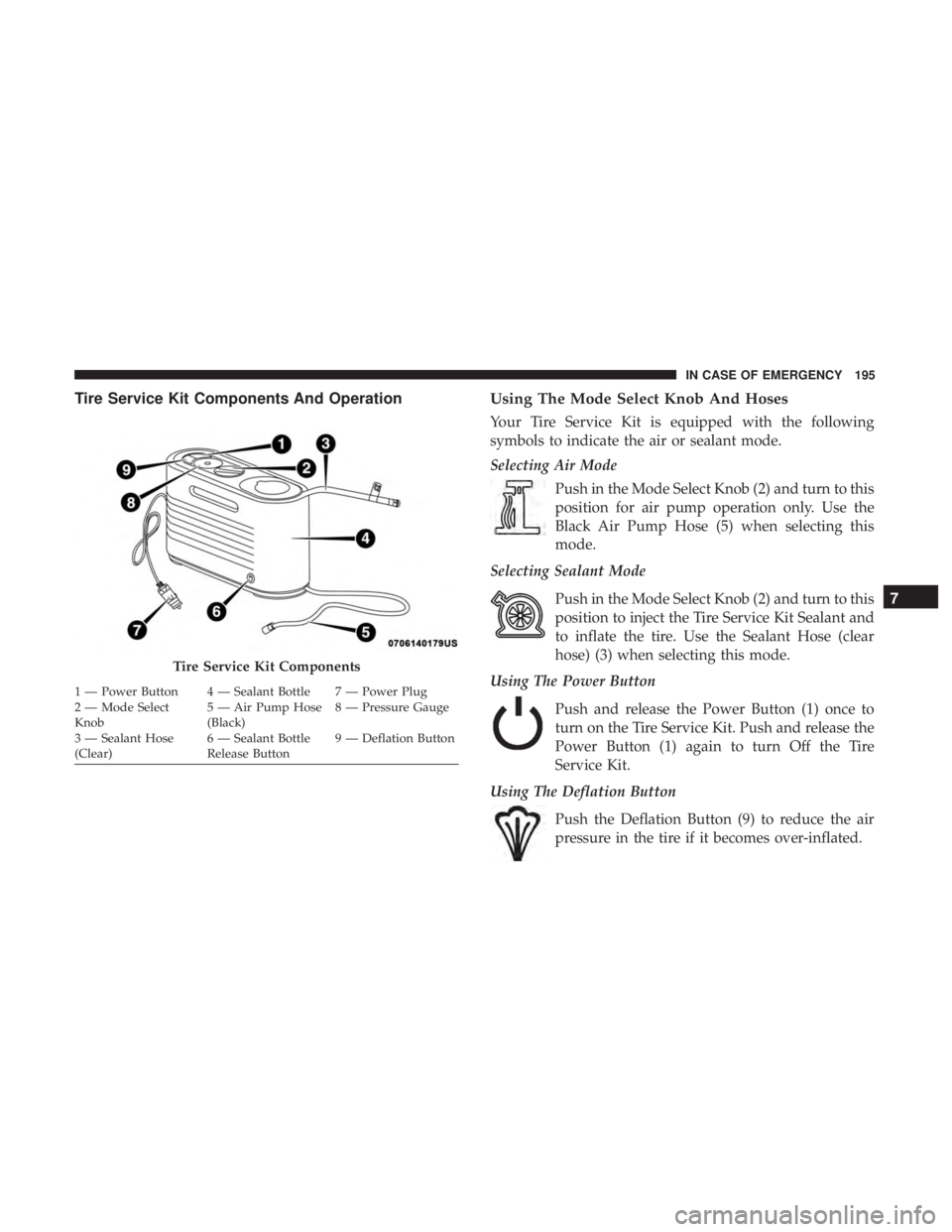
Your Tire Service Kit is equipped with the following
symbols to indicate the air or sealant mode.
Selecting Air Mode
Push in the Mode Select Knob (2) and turn to this
position for air pump operation only. Use the
Black Air Pump Hose (5) when selecting this
mode.
Selecting Sealant Mode
Push in the Mode Select Knob (2) and turn to this
position to inject the Tire Service Kit Sealant and
to inflate the tire. Use the Sealant Hose (clear
hose) (3) when selecting this mode.
Using The Power Button
Push and release the Power Button (1) once to
turn on the Tire Service Kit. Push and release the
Power Button (1) again to turn Off the Tire
Service Kit.
Using The Deflation Button
Push the Deflation Button (9) to reduce the air
pressure in the tire if it becomes over-inflated.
Tire Service Kit Components
1 — Power Button 4 — Sealant Bottle 7 — Power Plug
2 — Mode Select
Knob 5 — Air Pump Hose
(Black)8 — Pressure Gauge
3 — Sealant Hose
(Clear) 6 — Sealant Bottle
Release Button9 — Deflation Button
7
IN CASE OF EMERGENCY 195
Page 198 of 300

Tire Service Kit Usage Precautions
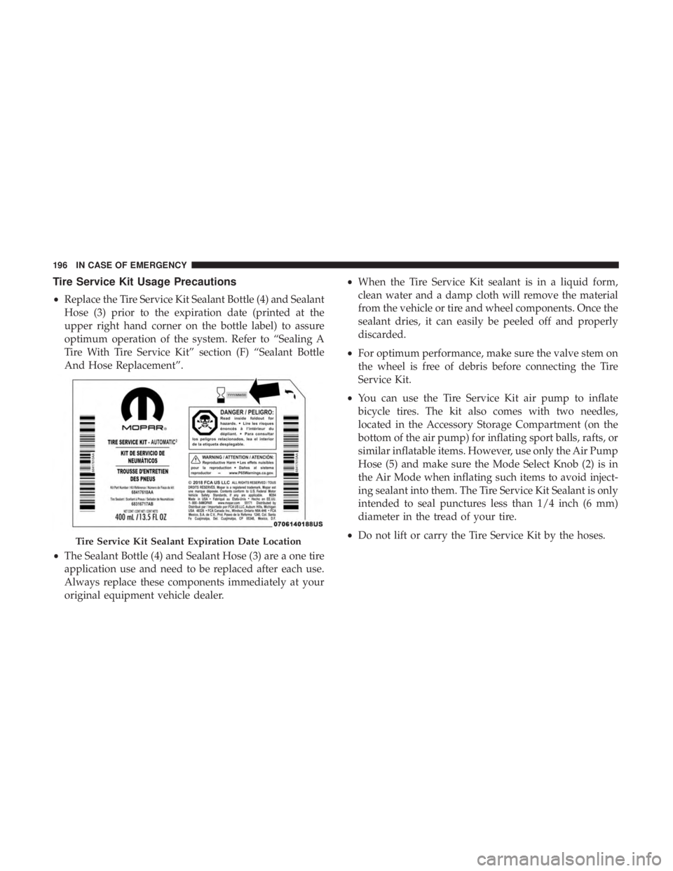
•Replace the Tire Service Kit Sealant Bottle (4) and Sealant
Hose (3) prior to the expiration date (printed at the
upper right hand corner on the bottle label) to assure
optimum operation of the system. Refer to “Sealing A
Tire With Tire Service Kit” section (F) “Sealant Bottle
And Hose Replacement”.
• The Sealant Bottle (4) and Sealant Hose (3) are a one tire
application use and need to be replaced after each use.
Always replace these components immediately at your
original equipment vehicle dealer. •
When the Tire Service Kit sealant is in a liquid form,
clean water and a damp cloth will remove the material
from the vehicle or tire and wheel components. Once the
sealant dries, it can easily be peeled off and properly
discarded.
• For optimum performance, make sure the valve stem on
the wheel is free of debris before connecting the Tire
Service Kit.
• You can use the Tire Service Kit air pump to inflate
bicycle tires. The kit also comes with two needles,
located in the Accessory Storage Compartment (on the
bottom of the air pump) for inflating sport balls, rafts, or
similar inflatable items. However, use only the Air Pump
Hose (5) and make sure the Mode Select Knob (2) is in
the Air Mode when inflating such items to avoid inject-
ing sealant into them. The Tire Service Kit Sealant is only
intended to seal punctures less than 1/4 inch (6 mm)
diameter in the tread of your tire.
• Do not lift or carry the Tire Service Kit by the hoses.
Tire Service Kit Sealant Expiration Date Location
196 IN CASE OF EMERGENCY