Page 156 of 300
WARNING!(Continued)
•ALWAYS make sure objects cannot fall or slide into
the driver ’s side floor area when the vehicle is
moving. Objects can become trapped under accelera-
tor, brake, or clutch pedals and could cause a loss of
vehicle control.
• NEVER place any objects under the floor mat (e.g.,
towels, keys, etc.). These objects could change the
position of the floor mat and may cause interference
with the accelerator, brake, or clutch pedals.
• If the vehicle carpet has been removed and re-
installed, always properly attach carpet to the floor
and check the floor mat fasteners are secure to the
vehicle carpet. Fully depress each pedal to check for
interference with the accelerator, brake, or clutch
pedals then re-install the floor mats.
• It is recommended to only use mild soap and water
to clean your floor mats. After cleaning, always check
your floor mat has been properly installed and is
secured to your vehicle using the floor mat fasteners
by lightly pulling mat.
Periodic Safety Checks You Should Make Outside
The Vehicle
Tires
Examine tires for excessive tread wear and uneven wear
patterns. Check for stones, nails, glass, or other objects
lodged in the tread or sidewall. Inspect the tread for cuts
and cracks. Inspect sidewalls for cuts, cracks, and bulges.
Check the wheel nuts for tightness. Check the tires (includ-
ing spare) for proper cold inflation pressure.
Lights
Have someone observe the operation of brake lights and
exterior lights while you work the controls. Check turn
signal and high beam indicator lights on the instrument
panel.
Door Latches
Check for proper closing, latching, and locking.
Fluid Leaks
Check area under vehicle after overnight parking for
coolant or other fluid leaks. If fluid leaks are suspected, the
cause should be located and corrected immediately.
154 SAFETY
Page 160 of 300
NOTE:
•If the key is held in the START position for more than 10
seconds “READY” mode will not be achieved. Return
the key to the OFF position, and then back to the START
position and hold for less than 10 seconds to achieve
“READY”.
• If the “READY” indicator fails to illuminate after you
have followed the normal starting procedure contact an
authorized dealer.
PARKING BRAKE
Before leaving the vehicle, make sure that the parking
brake is fully applied.
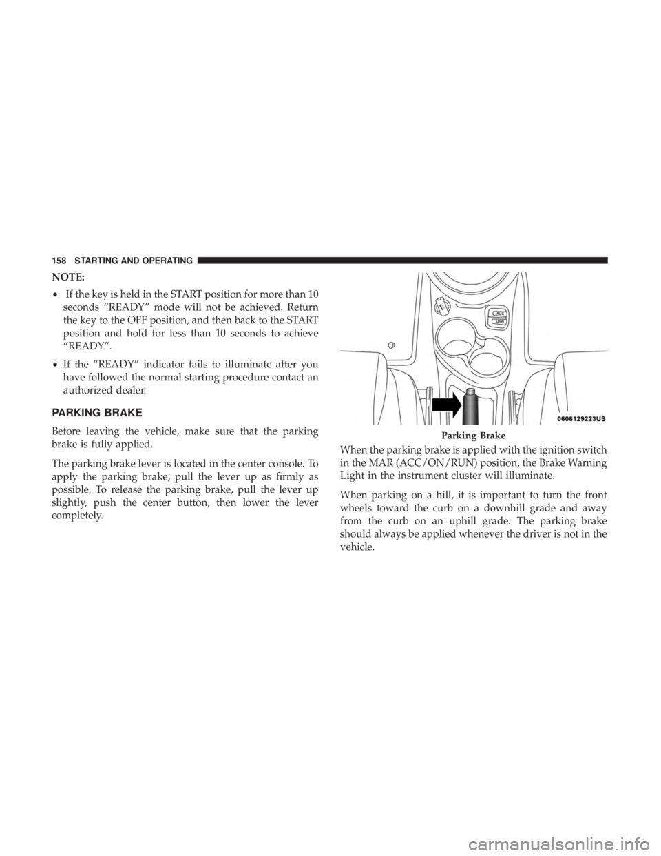
The parking brake lever is located in the center console. To
apply the parking brake, pull the lever up as firmly as
possible. To release the parking brake, pull the lever up
slightly, push the center button, then lower the lever
completely. When the parking brake is applied with the ignition switch
in the MAR (ACC/ON/RUN) position, the Brake Warning
Light in the instrument cluster will illuminate.
When parking on a hill, it is important to turn the front
wheels toward the curb on a downhill grade and away
from the curb on an uphill grade. The parking brake
should always be applied whenever the driver is not in the
vehicle.Parking Brake
158 STARTING AND OPERATING
Page 161 of 300
WARNING!
•Never leave children alone in a vehicle, or with
access to an unlocked vehicle.
• Allowing children to be in a vehicle unattended is
dangerous for a number of reasons. A child or others
could be seriously or fatally injured. Children
should be warned not to touch the parking brake,
brake pedal or the transmission push buttons.
• Do not leave the key fob in or near the vehicle (or in
a location accessible to children). A child could
operate power windows, other controls, or move the
vehicle.
• Be sure the parking brake is fully disengaged before
driving; failure to do so can lead to brake failure and
a collision.
• Always fully apply the parking brake when leaving
your vehicle, or it may roll and cause damage or
injury.
CAUTION!
If the Brake Warning Light remains on with the park-
ing brake released, a brake system malfunction is
indicated. Have the brake system serviced by an au-
thorized dealer immediately.
6
STARTING AND OPERATING 159
Page 166 of 300

Auto Park is enabled under the following condition:
•Key On (12 Volt ON and High Voltage OFF) or READY
mode (12 Volt ON and High Voltage ON).
NOTE:
• Auto Park is enabled (only once) at the beginning of
each key cycle and is re-enabled each time the vehicle
speed exceeds 8 mph (13 km/h).
The instrument cluster will display an Auto Shift To Park
message and chime once when Auto Park is activated.
Mode Of Operation With Key ON:
Auto Park will be engaged when the transmission is in
DRIVE, NEUTRAL or REVERSE and the following condi-
tions are detected:
• Seat Belt is unlatched
• Brake pedal is released
• Driver’s door is ajar
• Vehicle speed is less than 2 mph (3 km/h)
Mode Of Operation With Key OFF:
Auto Park will be engaged when the transmission is in
DRIVE, NEUTRAL or REVERSE and the vehicle speed is
less than 2 mph (3 km/h).POWER STEERING
The electric power steering system will give you good
vehicle response and increased ease of maneuverability in
tight spaces. The system will vary its assist to provide light
efforts while parking and good feel while driving. If the
electric steering system experiences a fault that prevents it
from providing assist, you will still have the ability to steer
the vehicle manually.
WARNING!
Continued operation with reduced or no power steer-
ing assist could pose a safety risk to yourself and
others. Service should be obtained as soon as possible.
If the Steering icon is flashing, it indicates that the vehicle
needs to be taken to an authorized dealer for service. It is
likely the vehicle has lost power steering assistance.
If the Steering icon is displayed and the “SERVICE POWER
STEERING” message is displayed on the instrument clus-
ter screen, they indicate that extreme steering maneuvers
may have occurred which caused an over temperature
condition in the power steering system. Once driving
conditions are safe, pull over and let the vehicle idle for a
164 STARTING AND OPERATING
Page 180 of 300

CAUTION!(Continued)
result in further damage. Such damage is not covered
by the New Vehicle Limited Warranty.
• Driving through standing water limits your vehicle’s
traction capabilities. Do not exceed 5 mph (8 km/h)
when driving through standing water.
• Driving through standing water limits your vehicle’s
braking capabilities, which increases stopping dis-
tances. Therefore, after driving through standing
water, drive slowly and lightly press on the brake
pedal several times to dry the brakes.
• Failure to follow these warnings may result in inju-
ries that are serious or fatal to you, your passengers,
and others around you.
EXTENDING YOUR DRIVING RANGE PER CHARGE
The drive system and cabin temperature management
features use the most energy from the high voltage battery.
Reducing energy draw from these features are the easiest
and most effective way to extend driving range. The 500e uses high voltage components to heat and cool
the cabin, so when using automatic climate control, con-
sider setting temperatures a few degrees higher or lower
during hot and cold days. If your 500e has been soaking in
hot or cold temperatures for an extended period, it is
recommended that the car be preconditioned using the
Uconnect smartphone app (not available in Canada) while
still plugged into a charging source. This will allow 500e to
use external power to establish a comfortable cabin tem-
perature before the drive and allow the battery to maintain
the temperature at significantly lower energy levels.
Additional tips:
•
Keep tires properly inflated.
• When practical, choose surface streets over the highway,
and work to maintain a steady speed.
• Avoid carrying nonessential cargo.
• Be mindful of adding external accessories that may
increase aerodynamic drag.
• Perform all scheduled maintenance at recommended
intervals.
178 STARTING AND OPERATING
Page 193 of 300
CavityMaxi Fuse Mini Fuse Description
F06 60 Amp Blue –Radiator Fan
F07 40 Amp Orange –Regen Brake Module
F08 40 Amp Orange –HVAC
F09 –5 Amp Tan Air Electric Heater
Charge Indicator
F10 –10 Amp Red Horn
F11 –10 Amp Red Electronic Vehicle Control Unit (EVCU)
F14 –5 Amp Tan High Beam (Shutter)
F15 –15 Amp Blue Cigar Lighter, AUX Power Outlet
F16 –10 Amp Red Humidity Sensor
VPAM
AC Compressor
F18 –5 Amp Tan Electronic Vehicle Control Unit (EVCU)
F19 –10 Amp Red HVAC
F20 –15 Amp Blue Heated Seats – If Equipped
F21 –20 Amp Yellow Radio
F23 –25 Amp Clear Anti-Lock Brake Valves
F24 –7.5 Amp Brown EPS
YAW Sensor
F30 –15 Amp Blue Fog Lamps
7
IN CASE OF EMERGENCY 191
Page 213 of 300
SCHEDULED SERVICING
Once A Month Or Before A Trip:
•Check windshield washer fluid level
• Check the tire inflation pressures and look for unusual
wear or damage
• Check the fluid levels of the coolant reservoirs and brake
master cylinder
• Check function of all interior and exterior lights
Maintenance Plan
Required Maintenance Intervals
Refer to the maintenance schedules on the following page
for the required maintenance intervals.
At Every Service Interval:
• Rotate the tires. Rotate at the first sign of irregular
wear.
• Inspect brake pads, shoes, rotors, drums, and hoses.
• Inspect battery cooling system protection and
hoses.
• Check and adjust hand brake.
Refer to the Maintenance Plan on the following pages for
the required maintenance intervals.
8
SERVICING AND MAINTENANCE 211
Page 227 of 300

4. Install the wiper blade pivot pin into the wiper bladeholder at the end of the wiper arm, and firmly press the
wiper blade until it snaps into place.
5. Lower the wiper blade and snap the pivot cap into place.
Brake System
In order to assure brake system performance, all brake
system components should be inspected periodically. Refer
to the “Maintenance Plan” in this section for the proper
maintenance intervals.
WARNING!
Riding the brakes can lead to brake failure and possi-
bly a collision. Driving with your foot resting or riding
on the brake pedal can result in abnormally high brake
temperatures, excessive lining wear, and possible
brake damage. You would not have your full braking
capacity in an emergency.
Brake Master Cylinder
The fluid in the master cylinder should be checked when
performing under hood services or immediately if the
“Brake Warning Light” is illuminated. Be sure to clean the top of the master cylinder area before
removing the cap. If necessary, add fluid to bring the fluid
level up to the requirements described on the brake fluid
reservoir. With disc brakes, fluid level can be expected to
fall as the brake pads wear. Brake fluid level should be
checked when pads are replaced. However, low fluid level
may be caused by a leak and a checkup may be needed.
Use only manufacturer’s recommended brake fluid. Refer
to “Fluids And Lubricants” in “Technical Specifications”
for further information.
WARNING!
•
Use only manufacturer’s recommended brake fluid.
Refer to “Fluids And Lubricants” in “Technical
Specifications” for further information. Using the
wrong type of brake fluid can severely damage your
brake system and/or impair its performance. The
proper type of brake fluid for your vehicle is also
identified on the original factory installed hydraulic
master cylinder reservoir.
• To avoid contamination from foreign matter or mois-
ture, use only new brake fluid or fluid that has been
(Continued)
8
SERVICING AND MAINTENANCE 225