2019 FIAT 124 SPIDER Owner handbook (in English)
-
 1
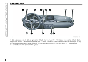
1 -
 2
2 -
 3
3 -
 4
4 -
 5
5 -
 6
6 -
 7
7 -
 8
8 -
 9
9 -
 10
10 -
 11
11 -
 12
12 -
 13
13 -
 14
14 -
 15
15 -
 16
16 -
 17
17 -
 18
18 -
 19
19 -
 20
20 -
 21
21 -
 22
22 -
 23
23 -
 24
24 -
 25
25 -
 26
26 -
 27
27 -
 28
28 -
 29
29 -
 30
30 -
 31
31 -
 32
32 -
 33
33 -
 34
34 -
 35
35 -
 36
36 -
 37
37 -
 38
38 -
 39
39 -
 40
40 -
 41
41 -
 42
42 -
 43
43 -
 44
44 -
 45
45 -
 46
46 -
 47
47 -
 48
48 -
 49
49 -
 50
50 -
 51
51 -
 52
52 -
 53
53 -
 54
54 -
 55
55 -
 56
56 -
 57
57 -
 58
58 -
 59
59 -
 60
60 -
 61
61 -
 62
62 -
 63
63 -
 64
64 -
 65
65 -
 66
66 -
 67
67 -
 68
68 -
 69
69 -
 70
70 -
 71
71 -
 72
72 -
 73
73 -
 74
74 -
 75
75 -
 76
76 -
 77
77 -
 78
78 -
 79
79 -
 80
80 -
 81
81 -
 82
82 -
 83
83 -
 84
84 -
 85
85 -
 86
86 -
 87
87 -
 88
88 -
 89
89 -
 90
90 -
 91
91 -
 92
92 -
 93
93 -
 94
94 -
 95
95 -
 96
96 -
 97
97 -
 98
98 -
 99
99 -
 100
100 -
 101
101 -
 102
102 -
 103
103 -
 104
104 -
 105
105 -
 106
106 -
 107
107 -
 108
108 -
 109
109 -
 110
110 -
 111
111 -
 112
112 -
 113
113 -
 114
114 -
 115
115 -
 116
116 -
 117
117 -
 118
118 -
 119
119 -
 120
120 -
 121
121 -
 122
122 -
 123
123 -
 124
124 -
 125
125 -
 126
126 -
 127
127 -
 128
128 -
 129
129 -
 130
130 -
 131
131 -
 132
132 -
 133
133 -
 134
134 -
 135
135 -
 136
136 -
 137
137 -
 138
138 -
 139
139 -
 140
140 -
 141
141 -
 142
142 -
 143
143 -
 144
144 -
 145
145 -
 146
146 -
 147
147 -
 148
148 -
 149
149 -
 150
150 -
 151
151 -
 152
152 -
 153
153 -
 154
154 -
 155
155 -
 156
156 -
 157
157 -
 158
158 -
 159
159 -
 160
160 -
 161
161 -
 162
162 -
 163
163 -
 164
164 -
 165
165 -
 166
166 -
 167
167 -
 168
168 -
 169
169 -
 170
170 -
 171
171 -
 172
172 -
 173
173 -
 174
174 -
 175
175 -
 176
176 -
 177
177 -
 178
178 -
 179
179 -
 180
180 -
 181
181 -
 182
182 -
 183
183 -
 184
184 -
 185
185 -
 186
186 -
 187
187 -
 188
188 -
 189
189 -
 190
190 -
 191
191 -
 192
192 -
 193
193 -
 194
194 -
 195
195 -
 196
196 -
 197
197 -
 198
198 -
 199
199 -
 200
200 -
 201
201 -
 202
202 -
 203
203 -
 204
204 -
 205
205 -
 206
206 -
 207
207 -
 208
208 -
 209
209 -
 210
210 -
 211
211 -
 212
212 -
 213
213 -
 214
214 -
 215
215 -
 216
216 -
 217
217 -
 218
218 -
 219
219 -
 220
220 -
 221
221 -
 222
222 -
 223
223 -
 224
224 -
 225
225 -
 226
226 -
 227
227
 HAZARD WARNING
LIGHTS
CONTROL
Press button fig. 103 to switch the
lights on/off.
Depress the hazard warning flasher and
all the direction indicators will flash. The
hazard warning indicator light
and")
 REPLACING A BULB
GENERAL
INSTRUCTIONS
170) 171) 172) 173) 174)
30) 31)
Before replacing a bulb check the
contacts for oxidation;
replace blown bulbs with others of
the same type and power;
after repla")
 Exterior light
Light bulbs Type Power
Front positions(versions with Full-LED
headlights)Full-LED(*)—
(versions with halogen headlights) W5W 5 W
High-beams(versions with Full-LED
headlights)Full-LED")
 Interior light
Light bulbCategory
Wattage UNECE(*)
Overhead light 10 —
Boot lid light 5 —
(*) UNECE stands for United Nations Economic Commission for Europe.
138
IN CASE OF EMERGENCY")
 REPLACING EXTERIOR
LIGHT BULBS
Headlights (low beam)
(versions with halogen bulb)
Proceed as follows:
if you are changing the right bulb,
start the engine, turn the steering wheel
all the way to the r")
 Front direction indicator lights
Proceed as follows:
if you are changing the right bulb,
start the engine, turn the steering wheel
all the way to the right, and turn off
engine. If you are changing th")
 Brake lights / Tail lights
Go to a Fiat Dealership when the
replacement of this lights is necessary.
Side direction indicator lights
Proceed as follows:
make sure the ignition is switched
off, and the")
 Rear direction indicator lights
Proceed as follows:
remove the retainers 1 fig. 114 and
the boot lid end trim;
remove the retainers 2 fig. 115 and
then partially peel back the boot lid side
trim;
disc")