2019 DODGE GRAND CARAVAN sensor
[x] Cancel search: sensorPage 141 of 490
NOTE:Keep magnetic materials away from the top of the
instrument panel, such as iPod’s, Mobile Phones, Laptops
and Radar Detectors. This is where the compass module is
located, and it can cause interference with the compass
sensor, and it may give false readings.
1. Turn the ignition switch ON.
2. Push and release the upordown arrow button until the
Setup (Customer-Programmable Features) menu is
reached, then push the rightarrow button. 3. Push and release the
downarrow button until the
“Compass Variance” message is displayed in the instru-
ment cluster display, then press the rightarrow button.
The last variance zone number displays in the instru-
ment cluster display.
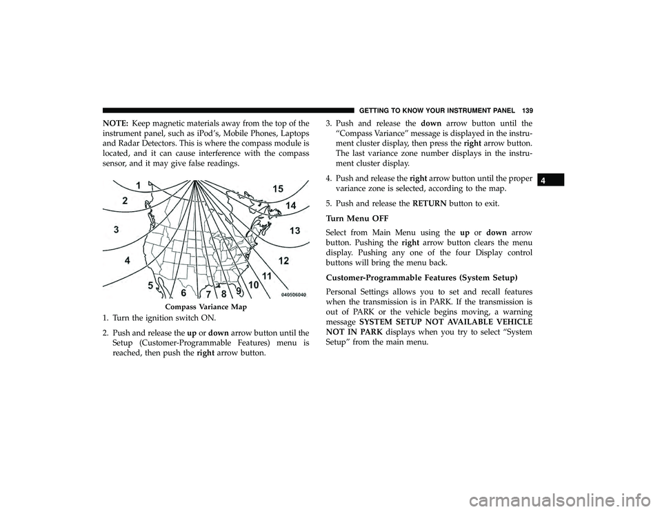
4. Push and release the rightarrow button until the proper
variance zone is selected, according to the map.
5. Push and release the RETURNbutton to exit.
Turn Menu OFF
Select from Main Menu using the upordown arrow
button. Pushing the rightarrow button clears the menu
display. Pushing any one of the four Display control
buttons will bring the menu back.
Customer-Programmable Features (System Setup)
Personal Settings allows you to set and recall features
when the transmission is in PARK. If the transmission is
out of PARK or the vehicle begins moving, a warning
message SYSTEM SETUP NOT AVAILABLE VEHICLE
NOT IN PARK displays when you try to select “System
Setup” from the main menu.
Compass Variance Map
4
GETTING TO KNOW YOUR INSTRUMENT PANEL 139
Page 145 of 490
function and operating information. To make your selec-
tion, push and release therightarrow button until “ON” or
“OFF” appears.
Flashers With Sliding Door
When this feature is selected, the signal lamps activate
when power or manual sliding doors are in operation,
signaling other drivers that someone may be exiting or
entering the vehicle. To make your selection, push and
release the rightarrow button until a check-mark appears
next to the feature showing the system has been activated
or the check-mark is removed, showing the system has
been deactivated.
Tilt Mirror In Reverse — If Equipped
When this feature is selected and the vehicle is placed in a
reverse gear, the driver’s side mirror will tilt downward to
allow the driver to see into the previous blind spot and
avoid objects in close proximity to the rear of the vehicle.
To make your selection, push and release the rightarrow
button until a check-mark appears next to the feature
showing the system has been activated, or the check-mark
is removed showing the system has been deactivated. Blind Spot Alert — If Equipped
There are three selections when operating Blind Spot Alert
(“Blind Spot Alert Lights,” “Blind Spot Alert Lights/
CHM,” and “Blind Spot Alert Off”). The Blind Spot Alert
feature can be activated in “Blind Spot Alert Lights” mode.
When this mode is selected, the Blind Spot Monitor (BSM)
system is activated and will only show a visual alert in the
outside mirrors. The Blind Spot Alert feature can be
activated in “Blind Spot Alert Lights/CHM” mode. In this
mode, the Blind Spot Monitor (BSM) will show a visual
alert in the outside mirrors as well as an audible alert when
the turn signal is on. When “Blind Spot Alert Off” is
selected, the Blind Spot Monitor (BSM) system is deacti-
vated.
To make your selection, push and release the
rightarrow
button until a check-mark appears next to the feature,
showing the system has been activated, or the check-mark
is removed, showing the system has been deactivated.
NOTE: If your vehicle has experienced any damage in the
area where the sensor is located, even if the fascia is not
damaged, the sensor may have become misaligned. Take
your vehicle to an authorized dealer to verify sensor
alignment. Having a sensor that is misaligned will result in
the BSM not operating to specification.
4
GETTING TO KNOW YOUR INSTRUMENT PANEL 143
Page 154 of 490
properly. Always check the TPMS malfunction telltale after
replacing one or more tires or wheels on your vehicle to
ensure that the replacement or alternate tires and wheels
allow the TPMS to continue to function properly.
CAUTION!
The TPMS has been optimized for the original equip-
ment tires and wheels. TPMS pressures and warning
have been established for the tire size equipped on
your vehicle. Undesirable system operation or sensor
damage may result when using replacement equip-
ment that is not of the same size, type, and/or style.
Aftermarket wheels can cause sensor damage. Using
aftermarket tire sealants may cause the Tire Pressure
Monitoring System (TPMS) sensor to become inoper-
able. After using an aftermarket tire sealant it is
recommended that you take your vehicle to your au-
thorized dealer to have your sensor function checked.
White Indicator Lights
— Speed Control Ready Indicator Light
This light will turn on when the speed control has been
turned on, but not set. Refer to “Speed Control — If
Equipped” in “Starting And Operating” for further infor-
mation.
Green Indicator Lights
— Speed Control SET Indicator Light
This light will turn on when the speed control is set. Refer
to “Speed Control” in “Starting And Operating” for further
information.
— Turn Signal Indicator Lights
When the left or right turn signal is activated, the turn
signal indicator will flash independently and the corre-
sponding exterior turn signal lamps will flash. Turn signals
can be activated when the multifunction lever is moved
down (left) or up (right).
152 GETTING TO KNOW YOUR INSTRUMENT PANEL
Page 165 of 490

7. Rotate the steering wheel back to center and then anadditional slightly more than one-half turn to the right.
8. Turn the ignition switch to the OFF position and then back to the ON position. If the sequence was completed
properly, the “ESC Off Indicator Light” will blink sev-
eral times to confirm HSA is disabled.
9. Repeat these steps if you want to return this feature to its previous setting.
Traction Control System (TCS)
This system monitors the amount of wheel spin of each of
the driven wheels. If wheel spin is detected, the TCS may
apply brake pressure to the spinning wheel(s) and/or
reduce vehicle power to provide enhanced acceleration
and stability. A feature of the TCS, Brake Limited Differen-
tial (BLD), functions similar to a limited slip differential
and controls the wheel spin across a driven axle. If one
wheel on a driven axle is spinning faster than the other, the
system will apply the brake of the spinning wheel. This
will allow more vehicle torque to be applied to the wheel
that is not spinning. BLD may remain enabled even if TCS
and ESC are in a reduced mode.
Electronic Stability Control (ESC)
This system enhances directional control and stability of
the vehicle under various driving conditions. ESC corrects
for oversteering or understeering of the vehicle by apply-
ing the brake of the appropriate wheel(s) to assist in
counteracting the oversteer or understeer condition. En-
gine power may also be reduced to help the vehicle
maintain the desired path.
ESC uses sensors in the vehicle to determine the vehicle
path intended by the driver and compares it to the actual
path of the vehicle. When the actual path does not match
the intended path, ESC applies the brake of the appropriate
wheel to assist in counteracting the oversteer or understeer
condition.
•Oversteer — when the vehicle is turning more than
appropriate for the steering wheel position.
• Understeer — when the vehicle is turning less than
appropriate for the steering wheel position.
The “ESC Activation/Malfunction Indicator Light” located
in the instrument cluster will start to flash as soon as the
ESC system becomes active. The “ESC Activation/
Malfunction Indicator Light” also flashes when the TCS is
active. If the “ESC Activation/Malfunction Indicator
5
SAFETY 163
Page 169 of 490

Trailer Sway Control (TSC)
TSC uses sensors in the vehicle to recognize an excessively
swaying trailer and will take the appropriate actions to
attempt to stop the sway. TSC will become active automati-
cally once an excessively swaying trailer is recognized.
Note that TSC cannot stop all trailers from swaying.
Always use caution when towing a trailer and follow the
trailer tongue weight recommendations. Refer to “Trailer
Towing” in “Starting And Operating” for further informa-
tion. When TSC is functioning, the “ESC Activation/
Malfunction Indicator Light” will flash, the engine power
may be reduced and you may feel the brakes being applied
to individual wheels to attempt to stop the trailer from
swaying. TSC is disabled when the ESC system is in the
“Partial Off” mode.
WARNING!
If TSC activates while driving, slow the vehicle down,
stop at the nearest safe location, and adjust the trailer
load to eliminate trailer sway.
AUXILIARY DRIVING SYSTEMS
Blind Spot Monitoring (BSM) — If Equipped
The Blind Spot Monitoring (BSM) system uses two radar
sensors, located inside the rear bumper fascia, to detect
highway licensable vehicles (automobiles, trucks, motor-
cycles, etc.) that enter the blind spot zones from the
rear/front/side of the vehicle.
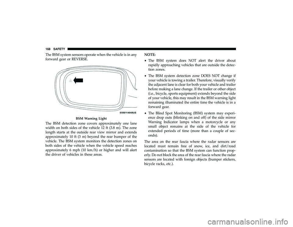
When the vehicle is started, the BSM warning light will
momentarily illuminate in both outside rear view mirrors
to let the driver know that the system is operational.
Rear Detection Zones
5
SAFETY 167
Page 170 of 490
The BSM system sensors operate when the vehicle is in any
forward gear or REVERSE.
The BSM detection zone covers approximately one lane
width on both sides of the vehicle 12 ft (3.8 m). The zone
length starts at the outside rear view mirror and extends
approximately 10 ft (3 m) beyond the rear bumper of the
vehicle. The BSM system monitors the detection zones on
both sides of the vehicle when the vehicle speed reaches
approximately 6 mph (10 km/h) or higher and will alert
the driver of vehicles in these areas.NOTE:
•
The BSM system does NOT alert the driver about
rapidly approaching vehicles that are outside the detec-
tion zones.
• The BSM system detection zone DOES NOT change if
your vehicle is towing a trailer. Therefore, visually verify
the adjacent lane is clear for both your vehicle and trailer
before making a lane change. If the trailer or other object
(i.e., bicycle, sports equipment) extends beyond the side
of your vehicle, this may result in the BSM warning light
remaining illuminated the entire time the vehicle is in a
forward gear.
• The Blind Spot Monitoring (BSM) system may experi-
ence drop outs (blinking on and off) of the side mirror
Warning Indicator lamps when a motorcycle or any
small object remains at the side of the vehicle for
extended periods of time (more than a couple of sec-
onds).
The area on the rear fascia where the radar sensors are
located must remain free of snow, ice, and dirt/road
contamination so that the BSM system can function prop-
erly. Do not block the area of the rear fascia where the radar
sensors are located with foreign objects (bumper stickers,
bicycle racks, etc.).
BSM Warning Light
168 SAFETY
Page 171 of 490
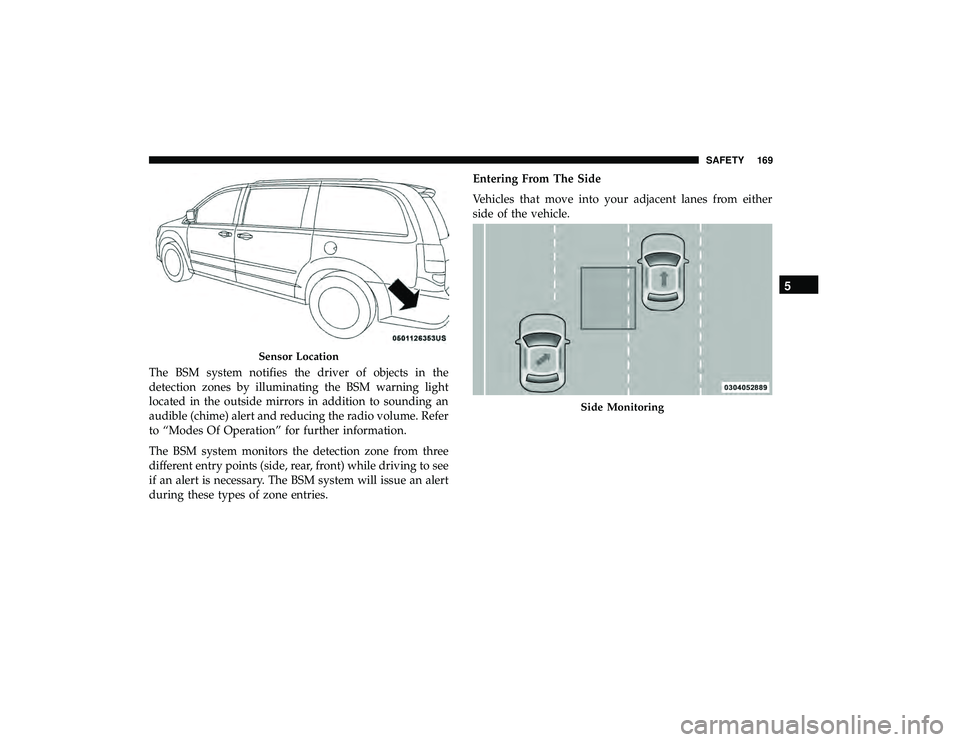
The BSM system notifies the driver of objects in the
detection zones by illuminating the BSM warning light
located in the outside mirrors in addition to sounding an
audible (chime) alert and reducing the radio volume. Refer
to “Modes Of Operation” for further information.
The BSM system monitors the detection zone from three
different entry points (side, rear, front) while driving to see
if an alert is necessary. The BSM system will issue an alert
during these types of zone entries.Entering From The Side
Vehicles that move into your adjacent lanes from either
side of the vehicle.
Sensor Location
Side Monitoring
5
SAFETY 169
Page 175 of 490
(5 km/h), to objects moving a maximum of approximately
20 mph (32 km/h), such as in parking lot situations.
NOTE:In a parking lot situation, oncoming vehicles can be
obscured by vehicles parked on either side. If the sensors
are blocked by other structures or vehicles, the system will
not be able to alert the driver.
When RCP is on and the vehicle is in REVERSE, the driver
is alerted using both the visual and audible alarms, includ-
ing reducing the radio volume.
WARNING!
Rear Cross Path Detection (RCP) is not a back up aid
system. It is intended to be used to help a driver detect
an oncoming vehicle in a parking lot situation. Drivers
must be careful when backing up, even when using
RCP. Always check carefully behind your vehicle, look
behind you, and be sure to check for pedestrians,
animals, other vehicles, obstructions, and blind spots
before backing up. Failure to do so can result in serious
injury or death.
Modes Of Operation
Modes Of Operation With Instrument Cluster Display
Three selectable modes of operation are available in the
instrument cluster display. Refer to “Instrument Cluster
Display” in “Getting To Know Your Instrument Panel” for
further information.
Blind Spot Alert Lights Only
When operating in Blind Spot Alert mode, the BSM system will
provide a visual alert in the appropriate side view mirror based
on a detected object. However, when the system is operating in
RCP, the system will respond with both visual and audible
alerts when a detected object is present. Whenever an audible
alert is requested, the radio volume is reduced.
Blind Spot Alert Lights/Chime
When operating in Blind Spot Alert Lights/Chime mode,
the BSM system will provide a visual alert in the appro-
priate side view mirror based on a detected object. If the
turn signal is then activated, and it corresponds to an alert
present on that side of the vehicle, an audible chime will
also be sounded. Whenever a turn signal and detected
object are present on the same side at the same time, both
the visual and audio alerts will be issued. In addition to the
audible alert the radio (if on) volume will be reduced.
5
SAFETY 173