2019 DODGE GRAND CARAVAN cv axle
[x] Cancel search: cv axlePage 161 of 490
WARNING!(Continued)
•The capabilities of an ABS equipped vehicle must
never be exploited in a reckless or dangerous manner
that could jeopardize the user ’s safety or the safety of
others.
ABS is designed to function with the OEM tires. Modifica-
tion may result in degraded ABS performance.
Anti-Lock Brake Warning Light
The yellow “Anti-Lock Brake Warning Light” will turn on
when the ignition is turned to the ON/RUN mode and
may stay on for as long as four seconds.
If the “Anti-Lock Brake Warning Light” remains on or
comes on while driving, it indicates that the anti-lock
portion of the brake system is not functioning and that
service is required. However, the conventional brake sys-
tem will continue to operate normally if the “Anti-Lock
Brake Warning Light” is on.
If the “Anti-Lock Brake Warning Light” is on, the brake
system should be serviced as soon as possible to restore the
benefits of anti-lock brakes. If the “Anti-Lock Brake Warning
Light” does not come on when the ignition is turned to the
ON/RUN mode, have the light repaired as soon as possible.
Electronic Brake Control System
Your vehicle is equipped with an advanced Electronic
Brake Control system (EBC). This system includes Elec-
tronic Brake Force Distribution (EBD), Anti-Lock Brake
System (ABS), Brake Assist System (BAS), Hill Start Assist
(HSA), Traction Control System (TCS), Electronic Stability
Control (ESC), and Electronic Roll Mitigation (ERM). These
systems work together to enhance both vehicle stability
and control in various driving conditions.
Your vehicle may also be equipped with Trailer Sway
Control (TSC).
Electronic Brake Force Distribution (EBD)
This function manages the distribution of the braking
torque between the front and rear axles by limiting braking
pressure to the rear axle. This is done to prevent overslip of
the rear wheels to avoid vehicle instability, and to prevent
the rear axle from entering ABS before the front axle.
Brake System Warning Light
The red “Brake System Warning Light” will turn on when
the ignition is turned to the ON/RUN mode and may stay
on for as long as four seconds.
5
SAFETY 159
Page 165 of 490

7. Rotate the steering wheel back to center and then anadditional slightly more than one-half turn to the right.
8. Turn the ignition switch to the OFF position and then back to the ON position. If the sequence was completed
properly, the “ESC Off Indicator Light” will blink sev-
eral times to confirm HSA is disabled.
9. Repeat these steps if you want to return this feature to its previous setting.
Traction Control System (TCS)
This system monitors the amount of wheel spin of each of
the driven wheels. If wheel spin is detected, the TCS may
apply brake pressure to the spinning wheel(s) and/or
reduce vehicle power to provide enhanced acceleration
and stability. A feature of the TCS, Brake Limited Differen-
tial (BLD), functions similar to a limited slip differential
and controls the wheel spin across a driven axle. If one
wheel on a driven axle is spinning faster than the other, the
system will apply the brake of the spinning wheel. This
will allow more vehicle torque to be applied to the wheel
that is not spinning. BLD may remain enabled even if TCS
and ESC are in a reduced mode.
Electronic Stability Control (ESC)
This system enhances directional control and stability of
the vehicle under various driving conditions. ESC corrects
for oversteering or understeering of the vehicle by apply-
ing the brake of the appropriate wheel(s) to assist in
counteracting the oversteer or understeer condition. En-
gine power may also be reduced to help the vehicle
maintain the desired path.
ESC uses sensors in the vehicle to determine the vehicle
path intended by the driver and compares it to the actual
path of the vehicle. When the actual path does not match
the intended path, ESC applies the brake of the appropriate
wheel to assist in counteracting the oversteer or understeer
condition.
•Oversteer — when the vehicle is turning more than
appropriate for the steering wheel position.
• Understeer — when the vehicle is turning less than
appropriate for the steering wheel position.
The “ESC Activation/Malfunction Indicator Light” located
in the instrument cluster will start to flash as soon as the
ESC system becomes active. The “ESC Activation/
Malfunction Indicator Light” also flashes when the TCS is
active. If the “ESC Activation/Malfunction Indicator
5
SAFETY 163
Page 244 of 490

After Starting — Warming Up The Engine
The idle speed is controlled automatically and it will
decrease as the engine warms up.
If Engine Fails To Start
WARNING!
•Never pour fuel or other flammable liquid into the
throttle body air inlet opening in an attempt to start
the vehicle. This could result in flash fire causing
serious personal injury.
• Do not attempt to push or tow your vehicle to get it
started. Vehicles equipped with an automatic trans-
mission cannot be started this way. Unburned fuel
could enter the catalytic converter and once the
engine has started, ignite and damage the converter
and vehicle.
• If the vehicle has a discharged battery, booster cables
may be used to obtain a start from a booster battery
or the battery in another vehicle. This type of start
can be dangerous if done improperly. Refer to “Jump
Starting Procedure” in “In Case Of Emergency” for
further information.
ENGINE BLOCK HEATER — IF EQUIPPED
The engine block heater warms the engine, and permits
quicker starts in cold weather. Connect the cord to a
standard 110-115 Volt AC electrical outlet with a grounded,
three-wire extension cord.
The engine block heater must be plugged in at least one
hour to have an adequate warming effect on the engine.
The engine block heater cord is routed under the hood on
the driver’s side of the vehicle. It has a removable cap that
is located on the driver side of the Integrated Power
Module.
WARNING!
Remember to disconnect the engine block heater cord
before driving. Damage to the 110-115 Volt electrical
cord could cause electrocution.
ENGINE BREAK-IN RECOMMENDATIONS
A long break-in period is not required for the engine and
drivetrain (transmission and axle) in your vehicle.
242 STARTING AND OPERATING
Page 270 of 490

NOTE:
•When the fuel nozzle “clicks” or shuts off, the fuel tank
is full.
• Tighten the fuel filler cap until you hear a “clicking”
sound. This is an indication that the fuel filler cap is
properly tightened.
• If the gas cap is not tightened properly, the MIL may
come on. Be sure the gas cap is tightened every time the
vehicle is refueled.
Loose Fuel Filler Cap Message
If the vehicle diagnostic system determines that the fuel
filler cap is loose, improperly installed, or damaged, a
”gASCAP” message will display in the odometer or a
“Check Gascap” message will display in the instrument
cluster. If this occurs, tighten the fuel filler cap properly
and press the Trip Odometer button to turn off the mes-
sage. If the problem continues, the message will appear the
next time the vehicle is started.
A loose, improperly installed, or damaged fuel filler cap
may also turn on the MIL.
VEHICLE LOADING
Certification Label
As required by National Highway Traffic Safety Adminis-
tration regulations, your vehicle has a certification label
affixed to the driver’s side door or pillar.
This label contains the month and year of manufacture,
Gross Vehicle Weight Rating (GVWR), Gross Axle Weight
Rating (GAWR) front and rear, and Vehicle Identification
Number (VIN). A Month-Day-Hour (MDH) number is
included on this label and indicates the Month, Day and
Hour of manufacture. The bar code that appears on the
bottom of the label is your VIN.
Gross Vehicle Weight Rating (GVWR)
The GVWR is the total permissible weight of your vehicle
including driver, passengers, vehicle, options and cargo.
The label also specifies maximum capacities of front and
rear axle systems (GAWR). Total load must be limited so
GVWR and front and rear GAWR are not exceeded.
Payload
The payload of a vehicle is defined as the allowable load
weight a truck can carry, including the weight of the driver,
all passengers, options and cargo.
268 STARTING AND OPERATING
Page 271 of 490
Gross Axle Weight Rating (GAWR)
The GAWR is the maximum permissible load on the front
and rear axles. The load must be distributed in the cargo
area so that the GAWR of each axle is not exceeded.
Each axle GAWR is determined by the components in the
system with the lowest load carrying capacity (axle,
springs, tires or wheels). Heavier axles or suspension
components sometimes specified by purchasers for in-
creased durability does not necessarily increase the vehi-
cle’s GVWR.
Tire Size
The tire size on the Vehicle Certification Label represents
the actual tire size on your vehicle. Replacement tires must
be equal to the load capacity of this tire size.
Rim Size
This is the rim size that is appropriate for the tire size
listed.
Inflation Pressure
This is the cold tire inflation pressure for your vehicle for
all loading conditions up to full GAWR.
Curb Weight
The curb weight of a vehicle is defined as the total weight
of the vehicle with all fluids, including vehicle fuel, at full
capacity conditions, and with no occupants or cargo loaded
into the vehicle. The front and rear curb weight values are
determined by weighing your vehicle on a commercial
scale before any occupants or cargo are added.
Loading
The actual total weight and the weight of the front and rear
of your vehicle at the ground can best be determined by
weighing it when it is loaded and ready for operation.
The entire vehicle should first be weighed on a commercial
scale to insure that the GVWR has not been exceeded. The
weight on the front and rear of the vehicle should then be
determined separately to be sure that the load is properly
distributed over the front and rear axle. Weighing the
vehicle may show that the GAWR of either the front or rear
axles has been exceeded but the total load is within the
specified GVWR. If so, weight must be shifted from front to
rear or rear to front as appropriate until the specified
weight limitations are met. Store the heavier items down
low and be sure that the weight is distributed equally. Stow
all loose items securely before driving.6
STARTING AND OPERATING 269
Page 273 of 490
Gross Axle Weight Rating (GAWR)
The GAWR is the maximum capacity of the front and rear
axles. Distribute the load over the front and rear axles
evenly. Make sure that you do not exceed either front or
rear GAWR. Refer to “Vehicle Loading/Vehicle Certifica-
tion Label” in “Starting And Operating” for further infor-
mation.
WARNING!
It is important that you do not exceed the maximum
front or rear GAWR. A dangerous driving condition
can result if either rating is exceeded. You could lose
control of the vehicle and have a collision.
Tongue Weight (TW)
The tongue weight is the downward force exerted on the
hitch ball by the trailer. You must consider this as part of
the load on your vehicle.
Trailer Frontal Area
The frontal area is the maximum height multiplied by the
maximum width of the front of a trailer.
Trailer Sway Control
The trailer sway control can be a mechanical telescoping
link that can be installed between the hitch receiver and the
trailer tongue that typically provides adjustable friction
associated with the telescoping motion to dampen any
unwanted trailer swaying motions while traveling.
If equipped, the electronic Trailer Sway Control (TSC)
recognizes a swaying trailer and automatically applies
individual wheel brakes and/or reduces engine power to
attempt to eliminate the trailer sway.
Weight-Carrying Hitch
A weight-carrying hitch supports the trailer tongue weight,
just as if it were luggage located at a hitch ball or some
other connecting point of the vehicle. These kinds of
hitches are the most popular on the market today and they
are commonly used to tow small and medium sized
trailers.
6
STARTING AND OPERATING 271
Page 274 of 490
Weight-Distributing Hitch
A weight-distributing system works by applying leverage
through spring (load) bars. They are typically used for
heavier loads to distribute trailer tongue weight to the tow
vehicle’s front axle and the trailer axle(s). When used in
accordance with the manufacturer’s directions, it provides
for a more level ride, offering more consistent steering and
brake control thereby enhancing towing safety. The addi-
tion of a friction/hydraulic sway control also dampens
sway caused by traffic and crosswinds and contributes
positively to tow vehicle and trailer stability. Trailer sway
control and a weight distributing (load equalizing) hitch
are recommended for heavier Tongue Weights (TW) and
may be required depending on vehicle and trailer
configuration/loading to comply with Gross Axle Weight
Rating (GAWR) requirements.
WARNING!
•An improperly adjusted Weight Distributing Hitch
system may reduce handling, stability, braking per-
formance, and could result in a collision.
• Weight Distributing Systems may not be compatible
with Surge Brake Couplers. Consult with your hitch
and trailer manufacturer or a reputable Recreational
Vehicle dealer for additional information.
272 STARTING AND OPERATING
Page 277 of 490
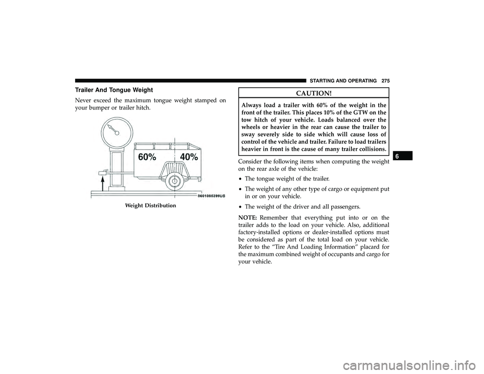
Trailer And Tongue Weight
Never exceed the maximum tongue weight stamped on
your bumper or trailer hitch.
CAUTION!
Always load a trailer with 60% of the weight in the
front of the trailer. This places 10% of the GTW on the
tow hitch of your vehicle. Loads balanced over the
wheels or heavier in the rear can cause the trailer to
sway severely side to side which will cause loss of
control of the vehicle and trailer. Failure to load trailers
heavier in front is the cause of many trailer collisions.
Consider the following items when computing the weight
on the rear axle of the vehicle:
• The tongue weight of the trailer.
• The weight of any other type of cargo or equipment put
in or on your vehicle.
• The weight of the driver and all passengers.
NOTE: Remember that everything put into or on the
trailer adds to the load on your vehicle. Also, additional
factory-installed options or dealer-installed options must
be considered as part of the total load on your vehicle.
Refer to the “Tire And Loading Information” placard for
the maximum combined weight of occupants and cargo for
your vehicle.
Weight Distribution
6
STARTING AND OPERATING 275