Page 282 of 490

Automatic Transmission
The DRIVE range can be selected when towing. However,
if frequent shifting occurs while in DRIVE, use the Elec-
tronic Range Select (ERS) shift control to manually select a
lower gear range.
NOTE:Using a lower gear range while operating the
vehicle under heavy loading conditions, will improve
performance and extend transmission life by reducing
excessive shifting and heat buildup. This action will also
provide better engine braking.
If you REGULARLY tow a trailer for more than 45 minutes
of continuous operation, then change the transmission
fluid and filter as specified for �police, taxi, fleet, or
frequent trailer towing.� Refer to the “Maintenance Plan”
for the proper maintenance intervals.
Electronic Range Select (ERS)
• When using the ERS shift control, select the highest gear
that allows for adequate performance and avoids fre-
quent downshifts. For example, choose “4” if the desired
speed can be maintained. Choose “3” or “2” if needed to
maintain the desired speed. •
To prevent excess heat generation, avoid continuous
driving at high RPM. Reduce vehicle speed as necessary
to avoid extended driving at high RPM. Return to a
higher gear range or vehicle speed when grade and road
conditions allow.
Speed Control — If Equipped
• Do not use on hilly terrain or with heavy loads.
• When using the speed control, if you experience speed
drops greater than 10 mph (16 km/h), disengage until
you can get back to cruising speed.
• Use speed control in flat terrain and with light loads to
maximize fuel efficiency.
Cooling System
To reduce potential for engine and transmission overheat-
ing, take the following actions:
City Driving
• In city traffic — while stopped, place the transmission in
NEUTRAL, but do not increase engine idle speed.
Highway Driving
• Reduce speed.
• Temporarily turn off air conditioning.
280 STARTING AND OPERATING
Page 286 of 490

CAUTION!
•Always check the depth of the standing water before
driving through it. Never drive through standing
water that is deeper than the bottom of the tire rims
mounted on the vehicle.
• Determine the condition of the road or the path that
is under water and if there are any obstacles in the
way before driving through the standing water.
• Do not exceed 5 mph (8 km/h) when driving through
standing water. This will minimize wave effects.
• Driving through standing water may cause damage
to your vehicle’s drivetrain components. Always in-
spect your vehicle’s fluids (i.e., engine oil, transmis-
sion, axle, etc.) for signs of contamination (i.e., fluid
that is milky or foamy in appearance) after driving
through standing water. Do not continue to operate
the vehicle if any fluid appears contaminated, as this
may result in further damage. Such damage is not
covered by the New Vehicle Limited Warranty.
• Getting water inside your vehicle’s engine can cause
it to lock up and stall out, and cause serious internal
damage to the engine. Such damage is not covered by
the New Vehicle Limited Warranty.
284 STARTING AND OPERATING
Page 287 of 490

IN CASE OF EMERGENCY
CONTENTS
�HAZARD WARNING FLASHERS ............286
� BULB REPLACEMENT ................... .287
▫ Replacement Bulbs ..................... .287
▫ Replacing Exterior Bulbs ..................288
� FUSES ............................... .290
▫ General Information .................... .291
▫ Totally Integrated Power Module (Fuses) ......292
� JACKING AND TIRE CHANGING ...........297
▫ Jack Location ........................ .298
▫ Spare Tire Tools ....................... .298
▫ To Access Spare Tire Winch Drive Nut ........299
▫ Spare Tire Removal .................... .301
▫ Spare Tire Removal Instructions .............301
▫ Preparations For Jacking .................303▫
Jacking Instructions .................... .303
▫ Securing The Compact Spare Tire ...........310
▫ Road Tire Installation ....................311
� TIRE SERVICE KIT — IF EQUIPPED ..........313
� JUMP STARTING ....................... .324
▫ Preparations For Jump Start ...............325
▫ Jump Starting Procedure ..................326
� IF YOUR ENGINE OVERHEATS .............327
� GEAR SELECTOR OVERRIDE ..............328
� FREEING A STUCK VEHICLE ..............329
� TOWING A DISABLED VEHICLE ............330
� ENHANCED ACCIDENT RESPONSE SYSTEM
(EARS) .............................. .331
� EVENT
DATA RECORDER (EDR) ............332
7
Page 293 of 490
WARNING!(Continued)
•If a general protection fuse for safety systems (air
bag system, braking system), power unit systems
(engine system, transmission system) or steering
system blows, contact an authorized dealer.
General Information
The fuses protect electrical systems against excessive cur-
rent.
When a device does not work, you must check the fuse
element inside the blade fuse for a break/melt.
Also, please be aware that when using power outlets for
extended periods of time with the engine off may result in
vehicle battery discharge.
Blade Fuses
1 — Fuse Element
2 — Blade Fuse with a good/functional fuse element.
3 — Blade fuse with a NOT functional / BAD fuse element (blown
fuse).
7
IN CASE OF EMERGENCY 291
Page 294 of 490

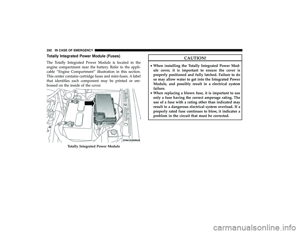
Totally Integrated Power Module (Fuses)
The Totally Integrated Power Module is located in the
engine compartment near the battery. Refer to the appli-
cable “Engine Compartment” illustration in this section.
This center contains cartridge fuses and mini-fuses. A label
that identifies each component may be printed or em-
bossed on the inside of the cover.
CAUTION!
•When installing the Totally Integrated Power Mod-
ule cover, it is important to ensure the cover is
properly positioned and fully latched. Failure to do
so may allow water to get into the Integrated Power
Module, and possibly result in a electrical system
failure.
• When replacing a blown fuse, it is important to use
only a fuse having the correct amperage rating. The
use of a fuse with a rating other than indicated may
result in a dangerous electrical system overload. If a
properly rated fuse continues to blow, it indicates a
problem in the circuit that must be corrected.
Totally Integrated Power Module
292 IN CASE OF EMERGENCY
Page 299 of 490

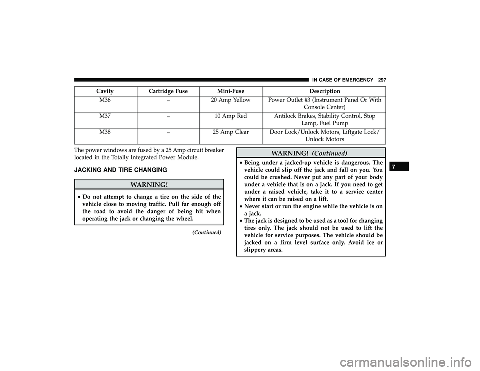
CavityCartridge Fuse Mini-Fuse Description
M36 –20 Amp Yellow Power Outlet #3 (Instrument Panel Or With
Console Center)
M37 –10 Amp Red Antilock Brakes, Stability Control, Stop
Lamp, Fuel Pump
M38 –25 Amp Clear Door Lock/Unlock Motors, Liftgate Lock/
Unlock Motors
The power windows are fused by a 25 Amp circuit breaker
located in the Totally Integrated Power Module.
JACKING AND TIRE CHANGING
WARNING!
• Do not attempt to change a tire on the side of the
vehicle close to moving traffic. Pull far enough off
the road to avoid the danger of being hit when
operating the jack or changing the wheel.
(Continued)
WARNING! (Continued)
•Being under a jacked-up vehicle is dangerous. The
vehicle could slip off the jack and fall on you. You
could be crushed. Never put any part of your body
under a vehicle that is on a jack. If you need to get
under a raised vehicle, take it to a service center
where it can be raised on a lift.
• Never start or run the engine while the vehicle is on
a jack.
• The jack is designed to be used as a tool for changing
tires only. The jack should not be used to lift the
vehicle for service purposes. The vehicle should be
jacked on a firm level surface only. Avoid ice or
slippery areas.7
IN CASE OF EMERGENCY 297
Page 305 of 490

Preparations For Jacking
1. Park the vehicle on a firm, level surface. Avoid ice orslippery areas.
WARNING!
Do not attempt to change a tire on the side of the
vehicle close to moving traffic. Pull far enough off the
road to avoid being hit when operating the jack or
changing the wheel.
2. Turn on the Hazard Warning flasher.
3. Apply the parking brake.
4. Place the gear selector into PARK.
5. Turn OFF the ignition.
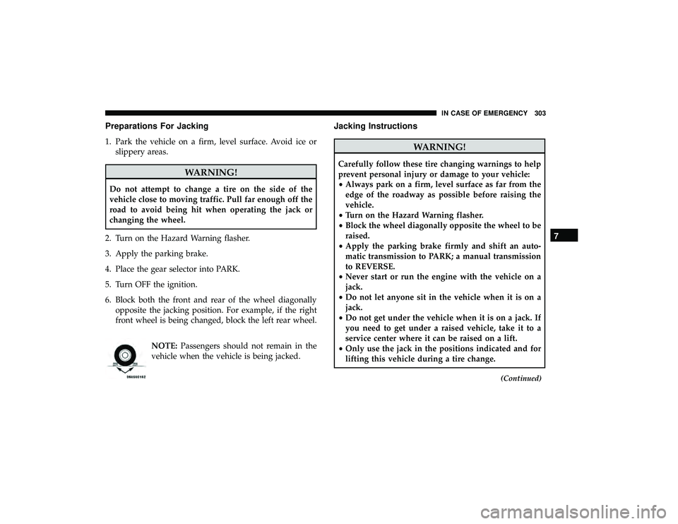
6. Block both the front and rear of the wheel diagonally opposite the jacking position. For example, if the right
front wheel is being changed, block the left rear wheel.
NOTE:Passengers should not remain in the
vehicle when the vehicle is being jacked.
Jacking Instructions
WARNING!
Carefully follow these tire changing warnings to help
prevent personal injury or damage to your vehicle:
• Always park on a firm, level surface as far from the
edge of the roadway as possible before raising the
vehicle.
• Turn on the Hazard Warning flasher.
• Block the wheel diagonally opposite the wheel to be
raised.
• Apply the parking brake firmly and shift an auto-
matic transmission to PARK; a manual transmission
to REVERSE.
• Never start or run the engine with the vehicle on a
jack.
• Do not let anyone sit in the vehicle when it is on a
jack.
• Do not get under the vehicle when it is on a jack. If
you need to get under a raised vehicle, take it to a
service center where it can be raised on a lift.
• Only use the jack in the positions indicated and for
lifting this vehicle during a tire change.
(Continued)
7
IN CASE OF EMERGENCY 303
Page 327 of 490

Preparations For Jump Start
The battery in your vehicle is located on the left side of the
engine compartment.
WARNING!
•Take care to avoid the radiator cooling fan whenever
the hood is raised. It can start anytime the ignition
switch is ON. You can be injured by moving fan
blades.
(Continued)
WARNING! (Continued)
•Remove any metal jewelry such as rings, watch
bands and bracelets that could make an inadvertent
electrical contact. You could be seriously injured.
• Batteries contain sulfuric acid that can burn your
skin or eyes and generate hydrogen gas which is
flammable and explosive. Keep open flames or
sparks away from the battery.
1. Apply the parking brake, shift the automatic transmis- sion into PARK and turn the ignition to OFF/LOCK.
2. Turn off the heater, radio, and all unnecessary electrical accessories.
3. If using another vehicle to jump start the battery, park the vehicle within the jumper cables reach, set the
parking brake and make sure the ignition is in the
OFF/LOCK position.
WARNING!
Do not allow vehicles to touch each other as this could
establish a ground connection and personal injury
could result.
Positive Battery Post
7
IN CASE OF EMERGENCY 325