2019 DODGE GRAND CARAVAN turn signal
[x] Cancel search: turn signalPage 176 of 490
NOTE:
•Whenever an audible alert is requested by the BSM
system, the radio volume is reduced.
• If the hazard flashers are on, the system will request the
appropriate visual alert only.
When the system is in RCP, the system shall respond with
both visual and audible alerts when a detected object is
present. Whenever an audible alert is requested, the radio
volume is reduced. Turn/hazard signal status is ignored;
the RCP state always requests the chime.
Blind Spot Alert Off
When the BSM system is turned off there will be no visual
or audible alerts from either the BSM or RCP systems.
NOTE: The BSM system will store the current operating
mode when the vehicle is shut off. Each time the vehicle is
started the previously stored mode will be recalled and
used.General Information
The following regulatory statement applies to all Radio
Frequency (RF) devices equipped in this vehicle:
This device complies with Part 15 of the FCC Rules and
with Industry Canada license-exempt RSS standard(s).
Operation is subject to the following two conditions:
1. This device may not cause harmful interference.
2. This device must accept any interference received, in- cluding interference that may cause undesired opera-
tion.
NOTE: Changes or modifications not expressly approved
by the party responsible for compliance could void the
user ’s authority to operate the equipment.
Tire Pressure Monitor System (TPMS)
The Tire Pressure Monitor System (TPMS) will warn the
driver of a low tire pressure based on the vehicle recom-
mended cold placard pressure.
174 SAFETY
Page 180 of 490
Service Tpm System
The TPMS Warning Light will flash on and off for 75
seconds, and remain on solid when a system fault is
detected. The system fault will also sound a chime. If the
ignition switch is cycled, this sequence will repeat, provid-
ing the system fault still exists. The TPMS Warning Light
will turn off when the fault condition no longer exists. A
system fault can occur with any of the following scenarios:
•Jamming due to electronic devices or driving next to
facilities emitting the same radio frequencies as the
TPMS sensors.
• Installing some form of aftermarket window tinting that
affects radio wave signals.
• Accumulation of excessive snow and/or ice around the
wheels or wheel housings.
• Using tire chains on the vehicle.
• Using wheels/tires not equipped with TPMS sensors.
Vehicles With Compact Spare
• The compact spare tire (if equipped) does not have a
TPMS sensor. Therefore the TPMS will not monitor the
pressure in the compact spare tire. •
If you install the compact spare tire in place of a road tire
that has a pressure below the low-pressure warning
limit, upon the next ignition switch cycle, a chime will
sound, a “LOW TIRE PRESSURE” message will be
displayed and the TPMS Warning Light will turn on.
• After driving for up to 20 minutes above 15 mph
(24 km/h), the TPMS Warning Light will flash on and off
for 75 seconds and then remain on solid.
• For each subsequent ignition switch cycle, a chime will
sound, the TPMS Warning Light will flash on and off for
75 seconds and then remain on solid.
• Once you repair or replace the original road tire and
reinstall it on the vehicle in place of the compact spare
tire, the TPMS will automatically update, and the TPMS
Warning Light will turn off as long as no tire pressure is
below the low-pressure warning limit in any of the four
active road tires.
TPMS Deactivation — If Equipped
The TPMS can be deactivated if replacing all four wheel
and tire assemblies (road tires) with wheel and tire assem-
blies that do not have TPMS Sensors, such as when
installing winter wheel and tire assemblies on your vehicle.
178 SAFETY
Page 183 of 490
Seat Belt Systems
Buckle up even though you are an excellent driver, even on
short trips. Someone on the road may be a poor driver and
could cause a collision that includes you. This can happen
far away from home or on your own street.
Research has shown that seat belts save lives, and they can
reduce the seriousness of injuries in a collision. Some of the
worst injuries happen when people are thrown from the
vehicle. Seat belts reduce the possibility of ejection and the
risk of injury caused by striking the inside of the vehicle.
Everyone in a motor vehicle should be belted at all times.
Enhanced Seat Belt Use Reminder System (BeltAlert)
Driver and Passenger BeltAlert (if equipped)
BeltAlert is a feature intended to remind the driver
and outboard front seat passenger (if equipped with
outboard front passenger seat BeltAlert) to buckle their
seat belts. The Belt Alert feature is active whenever the
ignition switch is in the START or ON/RUN position.
Initial Indication
If the driver is unbuckled when the ignition switch is first
in the START or ON/RUN position, a chime will signal for a few seconds. If the driver or outboard front seat passen-
ger (if equipped with outboard front passenger seat
BeltAlert) is unbuckled when the ignition switch is first in
the START or ON/RUN position the Seat Belt Reminder
Light will turn on and remain on until both outboard front
seat belts are buckled. The outboard front passenger seat
BeltAlert is not active when an outboard front passenger
seat is unoccupied.
BeltAlert Warning Sequence
The BeltAlert warning sequence is activated when the
vehicle is moving above a specified vehicle speed range
and the driver or outboard front seat passenger is unbuck-
led (if equipped with outboard front passenger seat
BeltAlert) (the outboard front passenger seat BeltAlert is
not active when the outboard front passenger seat is
unoccupied). The BeltAlert warning sequence starts by
blinking the Seat Belt Reminder Light and sounding an
intermittent chime. Once the BeltAlert warning sequence
has completed, the Seat Belt Reminder Light will remain on
until the seat belts are buckled. The BeltAlert warning
sequence may repeat based on vehicle speed until the
driver and occupied outboard front seat passenger seat
belts are buckled. The driver should instruct all occupants
to buckle their seat belts.
5
SAFETY 181
Page 239 of 490
WARNING!(Continued)
•ALWAYS make sure objects cannot fall or slide into
the driver ’s side floor area when the vehicle is
moving. Objects can become trapped under accelera-
tor, brake, or clutch pedals and could cause a loss of
vehicle control.
• NEVER place any objects under the floor mat (e.g.,
towels, keys, etc.). These objects could change the
position of the floor mat and may cause interference
with the accelerator, brake, or clutch pedals.
• If the vehicle carpet has been removed and re-
installed, always properly attach carpet to the floor
and check the floor mat fasteners are secure to the
vehicle carpet. Fully depress each pedal to check for
interference with the accelerator, brake, or clutch
pedals then re-install the floor mats.
• It is recommended to only use mild soap and water
to clean your floor mats. After cleaning, always check
your floor mat has been properly installed and is
secured to your vehicle using the floor mat fasteners
by lightly pulling mat.
Periodic Safety Checks You Should Make Outside
The Vehicle
Tires
Examine tires for excessive tread wear and uneven wear
patterns. Check for stones, nails, glass, or other objects
lodged in the tread or sidewall. Inspect the tread for cuts
and cracks. Inspect sidewalls for cuts, cracks, and bulges.
Check the wheel nuts for tightness. Check the tires (includ-
ing spare) for proper cold inflation pressure.
Lights
Have someone observe the operation of brake lights and
exterior lights while you work the controls. Check turn
signal and high beam indicator lights on the instrument
panel.
Door Latches
Check for proper closing, latching, and locking.
Fluid Leaks
Check area under the vehicle after overnight parking for
fuel, coolant, oil, or other fluid leaks. Also, if gasoline
fumes are detected or if fuel, or brake fluid leaks are
suspected. The cause should be located and corrected
immediately.
5
SAFETY 237
Page 280 of 490
Towing Requirements — Trailer Brakes
•Do not interconnect the hydraulic brake system or
vacuum system of your vehicle with that of the trailer.
This could cause inadequate braking and possible per-
sonal injury.
• An electronically actuated trailer brake controller is
required when towing a trailer with electronically actu-
ated brakes. When towing a trailer equipped with a
hydraulic surge actuated brake system, an electronic
brake controller is not required.
• Trailer brakes are recommended for trailers over
1,000 lbs (453 kg) and required for trailers in excess of
2,000 lbs (907 kg).
WARNING!
• Do not connect trailer brakes to your vehicle’s hy-
draulic brake lines. It can overload your brake sys-
tem and cause it to fail. You might not have brakes
when you need them and could have an accident.
• Towing any trailer will increase your stopping dis-
tance. When towing, you should allow for additional
space between your vehicle and the vehicle in front
of you. Failure to do so could result in an accident.
CAUTION!
If the trailer weighs more than 1,000 lbs (453 kg)
loaded, it should have its own brakes and they should
be of adequate capacity. Failure to do this could lead to
accelerated brake lining wear, higher brake pedal
effort, and longer stopping distances.
Towing Requirements — Trailer Lights And Wiring
Whenever you pull a trailer, regardless of the trailer size,
stoplights and turn signals on the trailer are required for
motoring safety.
The Trailer Tow Package may include a four- and seven-pin
wiring harness. Use a factory approved trailer harness and
connector.
NOTE: Do not cut or splice wiring into the vehicle’s wiring
harness.
The electrical connections are all complete to the vehicle
but you must mate the harness to a trailer connector. Refer
to the following illustrations.
278 STARTING AND OPERATING
Page 288 of 490
HAZARD WARNING FLASHERS
The Hazard Warning flasher switch is located in the lower
center area of the instrument panel.Push the switch to turn on the Hazard Warning
flasher. When the switch is activated, all direc-
tional turn signals will flash on and off to warn
oncoming traffic of an emergency. Push the
switch a second time to turn off the Hazard Warning
flashers. This is an emergency warning system and it should not be
used when the vehicle is in motion. Use it when your
vehicle is disabled and it is creating a safety hazard for
other motorists.
When you must leave the vehicle to seek assistance, the
Hazard Warning flashers will continue to operate even
though the ignition is placed in the OFF position.
NOTE:
With extended use, the Hazard Warning flashers
may wear down your battery.
286 IN CASE OF EMERGENCY
Page 290 of 490
Exterior Bulbs
Bulb Number
Headlamp H11LL
Fog Lamp – If Equipped PSX24W
Front Side Marker, Park/Turn Signal 3757A or PY27/7W
Rear Tail, Stop, Turn Signal Lamp LED (Serviced at authorized dealer)
Center High-Mounted Stop Lamp LED (Serviced at authorized dealer)
Backup Lamp 3157
License 168
NOTE: All of the interior bulbs are glass wedge base or
glass cartridge types. Aluminum base bulbs are not ap-
proved and should not be used for replacement.
Replacing Exterior Bulbs
Headlamps
1. Raise the hood to access the rear of the headlamp housing.
2. Slide the red lock tab rearward on the connector, then depress the tab and remove the connector from the bulb.
3. Twist the headlamp bulb and pull the bulb from the headlamp housing. 4. Install the new headlamp bulb and twist until locked
into the headlamp housing.
CAUTION!
Do not touch the new bulb with your fingers. Oil
contamination will severely shorten bulb life. If the
bulb comes in contact with an oily surface, clean the
bulb with rubbing alcohol.
5. Connect the wiring connector to bulb and slide red lock tab forward.
288 IN CASE OF EMERGENCY
Page 291 of 490
Front Park/Turn Signal Lamps
1. Raise the hood to access the rear of the headlamphousing.
2. Twist the turn signal socket and remove from the headlamp housing, then pull the bulb out.
3.
Push the new bulb into the socket and reinstall the socket
by twisting until locked into the headlamp housing.
Fog Lamps
NOTE: Access to the fog lamp bulb is from the rear of the
fascia. On the left rear side of the fascia, remove the push
pin and lower the hinged access door on the air dam.
1. From behind the bumper fascia, or the access panel on the air dam, squeeze the two tabs on the side of the bulb
socket and pull straight out from the fog lamp.
CAUTION!
Do not touch the new bulb with your fingers. Oil
contamination will severely shorten bulb life. If the
bulb comes in contact with an oily surface, clean the
bulb with rubbing alcohol.
2. Disconnect the wire harness from the bulb. 3. Reconnect the wiring harness to the new bulb and
reinstall by inserting the new bulb straight into the fog
lamp until it locks into place.
Rear Tail, Stop, Turn Signal, Side Marker And
Backup Lamps
1. Raise the liftgate.
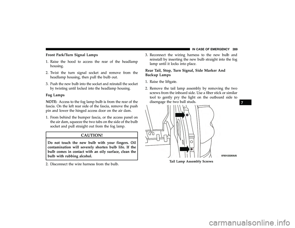
2. Remove the tail lamp assembly by removing the twoscrews from the inboard side. Use a fiber stick or similar
tool to gently pry the light on the outboard side to
disengage the two ball studs.
Tail Lamp Assembly Screws
7
IN CASE OF EMERGENCY 289