Page 280 of 490

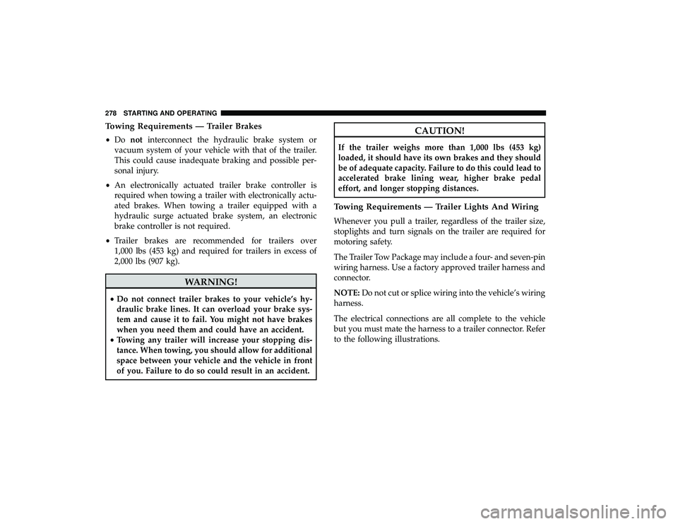
Towing Requirements — Trailer Brakes
•Do not interconnect the hydraulic brake system or
vacuum system of your vehicle with that of the trailer.
This could cause inadequate braking and possible per-
sonal injury.
• An electronically actuated trailer brake controller is
required when towing a trailer with electronically actu-
ated brakes. When towing a trailer equipped with a
hydraulic surge actuated brake system, an electronic
brake controller is not required.
• Trailer brakes are recommended for trailers over
1,000 lbs (453 kg) and required for trailers in excess of
2,000 lbs (907 kg).
WARNING!
• Do not connect trailer brakes to your vehicle’s hy-
draulic brake lines. It can overload your brake sys-
tem and cause it to fail. You might not have brakes
when you need them and could have an accident.
• Towing any trailer will increase your stopping dis-
tance. When towing, you should allow for additional
space between your vehicle and the vehicle in front
of you. Failure to do so could result in an accident.
CAUTION!
If the trailer weighs more than 1,000 lbs (453 kg)
loaded, it should have its own brakes and they should
be of adequate capacity. Failure to do this could lead to
accelerated brake lining wear, higher brake pedal
effort, and longer stopping distances.
Towing Requirements — Trailer Lights And Wiring
Whenever you pull a trailer, regardless of the trailer size,
stoplights and turn signals on the trailer are required for
motoring safety.
The Trailer Tow Package may include a four- and seven-pin
wiring harness. Use a factory approved trailer harness and
connector.
NOTE: Do not cut or splice wiring into the vehicle’s wiring
harness.
The electrical connections are all complete to the vehicle
but you must mate the harness to a trailer connector. Refer
to the following illustrations.
278 STARTING AND OPERATING
Page 281 of 490
NOTE:
•Disconnect trailer wiring connector from the vehicle
before launching a boat (or any other device plugged
into vehicle’s electrical connect) into water.
• Be sure to reconnect once clear from water area.
Towing Tips
Before setting out on a trip, practice turning, stopping, and
backing up the trailer in an area located away from heavy
traffic.Four-Pin Connector
1 — Female Pins 4 — Park
2 — Male Pin 5 — Left Stop/Turn
3 — Ground 6 — Right Stop/Turn
Seven-Pin Connector
1 — Battery5 — Ground
2 — Backup Lamps 6 — Left Stop/Turn
3 — Right Stop/Turn 7 — Running Lamps
4 — Electric Brakes
6
STARTING AND OPERATING 279
Page 293 of 490
WARNING!(Continued)
•If a general protection fuse for safety systems (air
bag system, braking system), power unit systems
(engine system, transmission system) or steering
system blows, contact an authorized dealer.
General Information
The fuses protect electrical systems against excessive cur-
rent.
When a device does not work, you must check the fuse
element inside the blade fuse for a break/melt.
Also, please be aware that when using power outlets for
extended periods of time with the engine off may result in
vehicle battery discharge.
Blade Fuses
1 — Fuse Element
2 — Blade Fuse with a good/functional fuse element.
3 — Blade fuse with a NOT functional / BAD fuse element (blown
fuse).
7
IN CASE OF EMERGENCY 291
Page 294 of 490

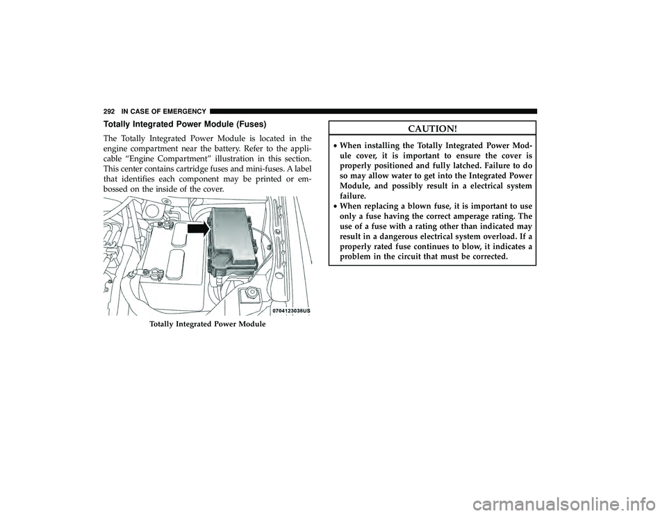
Totally Integrated Power Module (Fuses)
The Totally Integrated Power Module is located in the
engine compartment near the battery. Refer to the appli-
cable “Engine Compartment” illustration in this section.
This center contains cartridge fuses and mini-fuses. A label
that identifies each component may be printed or em-
bossed on the inside of the cover.
CAUTION!
•When installing the Totally Integrated Power Mod-
ule cover, it is important to ensure the cover is
properly positioned and fully latched. Failure to do
so may allow water to get into the Integrated Power
Module, and possibly result in a electrical system
failure.
• When replacing a blown fuse, it is important to use
only a fuse having the correct amperage rating. The
use of a fuse with a rating other than indicated may
result in a dangerous electrical system overload. If a
properly rated fuse continues to blow, it indicates a
problem in the circuit that must be corrected.
Totally Integrated Power Module
292 IN CASE OF EMERGENCY
Page 326 of 490
5. Pull the bottle away from the Compressor.
NOTE:
•For sealant bottle installation, follow these steps reverse
order.
• Replacement sealant bottles are available at authorized
service centers.JUMP STARTING
If your vehicle has a discharged battery it can be jump
started using a set of jumper cables and a battery in another
vehicle or by using a portable battery booster pack. Jump
starting can be dangerous if done improperly so please
follow the procedures in this section carefully.
NOTE: When using a portable battery booster pack follow
the manufacturer ’s operating instructions and precautions.
WARNING!
Do not attempt jump starting if the battery is frozen. It
could rupture or explode and cause personal injury.
CAUTION!
Do not use a portable battery booster pack or any other
booster source with a system voltage greater than 12
Volts or damage to the battery, starter motor, alternator
or electrical system may occur.
Remove The Bottle
324 IN CASE OF EMERGENCY
Page 327 of 490

Preparations For Jump Start
The battery in your vehicle is located on the left side of the
engine compartment.
WARNING!
•Take care to avoid the radiator cooling fan whenever
the hood is raised. It can start anytime the ignition
switch is ON. You can be injured by moving fan
blades.
(Continued)
WARNING! (Continued)
•Remove any metal jewelry such as rings, watch
bands and bracelets that could make an inadvertent
electrical contact. You could be seriously injured.
• Batteries contain sulfuric acid that can burn your
skin or eyes and generate hydrogen gas which is
flammable and explosive. Keep open flames or
sparks away from the battery.
1. Apply the parking brake, shift the automatic transmis- sion into PARK and turn the ignition to OFF/LOCK.
2. Turn off the heater, radio, and all unnecessary electrical accessories.
3. If using another vehicle to jump start the battery, park the vehicle within the jumper cables reach, set the
parking brake and make sure the ignition is in the
OFF/LOCK position.
WARNING!
Do not allow vehicles to touch each other as this could
establish a ground connection and personal injury
could result.
Positive Battery Post
7
IN CASE OF EMERGENCY 325
Page 328 of 490

Jump Starting Procedure
WARNING!
Failure to follow this jump starting procedure could
result in personal injury or property damage due to
battery explosion.
CAUTION!
Failure to follow these procedures could result in
damage to the charging system of the booster vehicle
or the discharged vehicle.
Connecting The Jumper Cables
1. Connect the positive (+)end of the jumper cable to the
positive (+)post of the discharged vehicle.
2. Connect the opposite end of the positive (+)jumper
cable to the positive (+)post of the booster battery.
3. Connect the negative (-)end of the jumper cable to the
negative (-)post of the booster battery.
4. Connect the opposite end of the negative (-)jumper
cable to a good engine ground (exposed metal part of the discharged vehicle’s engine) away from the battery
and the fuel injection system.
WARNING!
Do not connect the jumper cable to the negative (-) post
of the discharged battery. The resulting electrical spark
could cause the battery to explode and could result in
personal injury. Only use the specific ground point, do
not use any other exposed metal parts.
5. Start the engine in the vehicle that has the booster battery, let the engine idle for a few minutes, and then
start the engine in the vehicle with the discharged
battery.
6. Once the engine is started, remove the jumper cables in the reverse sequence:
Disconnecting The Jumper Cables
1. Disconnect the negative (-)end of the jumper cable from
the engine ground of the vehicle with the discharged
battery.
2. Disconnect the opposite end of the negative (-)jumper
cable from the negative (-)post of the booster battery.
326 IN CASE OF EMERGENCY
Page 477 of 490

Cupholders...........................113,385
Customer Assistance ....................... .466
Cybersecurity ............................ .403
Daytime Brightness, Interior Lights ...............66
Daytime Running Lights ................... .61, 62
Dealer Service ............................ .341
Defroster, Windshield ....................... .235
Delay (Intermittent) Wipers ....................67
Diagnostic System, Onboard ...................153
Dimmer Switch Headlight ........................... .61, 62
Dipsticks Automatic Transmission ................... .357
Oil (Engine) ........................... .340
Power Steering ......................... .254
Disabled Vehicle Towing .................... .330
Disposal Antifreeze (Engine Coolant) .................353
Door Ajar ............................ .146, 147
Door Ajar Light ....................... .146, 147
Door Locks Automatic ..............................29
Doors ....................................27
Driver ’s Seat Back Tilt .................... .32, 33Driving
Through Flowing, Rising, Or Shallow Standing
Water ................................ .283
DVD Player (Video Entertainment System) .........411
E-85 Fuel ............................... .394
Economy (Fuel) Mode ...................... .247
Electrical Power Outlets ......................115
Electric Brake Control System ..................159
Anti-Lock Brake System ................... .158
Traction Control System ................... .163
Electric Remote Mirrors .......................59
Electronic Speed Control (Cruise Control) .........255
Electronic Stability Control (ESC) ...............163
Electronic Throttle Control Warning Light .........146
Emergency, In Case Of Freeing Vehicle When Stuck .................329
Hazard Warning Flasher ...................286
Jacking ........................ .297,
303, 357
Jump Starting .......................... .324
Emission Control System Maintenance ............154
Engine ................................. .339
Air Cleaner ............................ .344
Block Heater ........................... .242
Break-In Recommendations .................242
12
INDEX 475