2019 DODGE CHARGER SRT battery
[x] Cancel search: batteryPage 189 of 496
Your vehicle may also be designed to perform any of these
other functions in response to the Enhanced Accident
Response System:
•Turn off the Fuel Filter Heater, Turn off the HVAC
Blower Motor, Close the HVAC Circulation Door
• Cut off battery power to the:
• Engine
• Electric Motor (if equipped)
• Electric power steering
• Brake booster
• Electric park brake
• Automatic transmission gear selector
• Horn
• Front wiper
• Headlamp washer pump
NOTE:
After an accident, remember to cycle the ignition to
the STOP (OFF/LOCK) position and remove the key from the
ignition switch to avoid draining the battery. Carefully check
the vehicle for fuel leaks in the engine compartment and on
the ground near the engine compartment and fuel tank before
resetting the system and starting the engine. If there are no
fuel leaks or damage to the vehicle electrical devices (e.g.
headlights) after an accident, reset the system by following the procedure described below. If you have any doubt, contact an
authorized dealer.
Enhanced Accident Response System Reset Procedure
In order to reset the Enhanced Accident Response System
functions after an event, the ignition switch must be
changed from ignition START or ON/RUN to ignition OFF.
Carefully check the vehicle for fuel leaks in the engine
compartment and on the ground near the engine compart-
ment and fuel tank before resetting the system and starting
the engine.
Maintaining Your Air Bag System
WARNING!
•
Modifications to any part of the air bag system could
cause it to fail when you need it. You could be
injured if the air bag system is not there to protect
you. Do not modify the components or wiring, in-
cluding adding any kind of badges or stickers to the
steering wheel hub trim cover or the upper passenger
side of the instrument panel. Do not modify the front
bumper, vehicle body structure, or add aftermarket
side steps or running boards.
(Continued)
5
SAFETY 187
Page 219 of 496
WARNING!(Continued)
•If the vehicle has a discharged battery, booster cables
may be used to obtain a start from a booster battery
or the battery in another vehicle. This type of start
can be dangerous if done improperly. Refer to “Jump
Starting Procedure” in “In Case Of Emergency” for
further information.
CAUTION!
To prevent damage to the starter, do not continuously
crank the engine for more than 25 seconds at a time.
Wait 60 seconds before trying again.
After Starting
The idle speed is controlled automatically, and it will
decrease as the engine warms up.
ENGINE BLOCK HEATER — IF EQUIPPED
The engine block heater warms the engine, and permits
quicker starts in cold weather. Connect the cord to a
standard 110-115 Volt AC electrical outlet with a grounded,
three-wire extension cord. The engine block heater must be plugged in at least one
hour to have an adequate warming effect on the engine.
The engine block heater cord is routed under the hood on
the driver side of the vehicle. It has a removable cap that is
located near the air box.
WARNING!
Remember to disconnect the engine block heater cord
before driving. Damage to the 110-115 Volt electrical
cord could cause electrocution.
ENGINE BREAK-IN RECOMMENDATIONS
The following tips will be helpful in obtaining optimum
performance and maximum durability for your new SRT
vehicle.
Despite modern technology and World Class manufactur-
ing methods, the moving parts of the vehicle must still
wear in with each other. This wearing in occurs mainly
during the first 500 miles (805 km) and continues through
the first oil change interval.
6
STARTING AND OPERATING 217
Page 285 of 496

HAZARD WARNING FLASHERS
The Hazard Warning flasher switch is located on the switch
bank just above the climate controls.Push the switch to turn on the Hazard Warning
flasher. When the switch is activated, all direc-
tional turn signals will flash on and off to warn
oncoming traffic of an emergency. Push the
switch a second time to turn off the Hazard Warning
flashers.
This is an emergency warning system and it should not be
used when the vehicle is in motion. Use it when your
vehicle is disabled and it is creating a safety hazard for
other motorists.
When you must leave the vehicle to seek assistance, the
Hazard Warning flashers will continue to operate even
though the ignition is placed in the OFF position.
NOTE: With extended use, the Hazard Warning flashers
may discharge the battery.
ASSIST AND SOS MIRROR — IF EQUIPPED
If equipped, the rearview mirror contains an ASSIST and a
SOS button.
Assist And SOS Mirror
7
IN CASE OF EMERGENCY 283
Page 288 of 496
WARNING!
•If anyone in the vehicle could be in danger (e.g., fire
or smoke is visible, dangerous road conditions or
location), do not wait for voice contact from an
Emergency Services Agent. All occupants should exit
the vehicle immediately and move to a safe location.
• Never place anything on or near the vehicle’s oper-
able network and GPS antennas. You could prevent
operable network and GPS signal reception, which
can prevent your vehicle from placing an emergency
call. An operable network and GPS signal reception
is required for the SOS Call system to function
properly.
• The SOS Call system is embedded into the vehicle’s
electrical system. Do not add aftermarket electrical
equipment to the vehicle’s electrical system. This
may prevent your vehicle from sending a signal to
initiate an emergency call. To avoid interference that
can cause the SOS Call system to fail, never add
aftermarket equipment (e.g., two-way mobile radio,
CB radio, data recorder, etc.) to your vehicle’s electri-
cal system or modify the antennas on your vehicle. IF
YOUR VEHICLE LOSES BATTERY POWER FOR
(Continued)
WARNING! (Continued)
ANY REASON (INCLUDING DURING OR AFTER
AN ACCIDENT), THE UCONNECT FEATURES,
APPS AND SERVICES, AMONG OTHERS, WILL
NOT OPERATE.
• Modifications to any part of the SOS Call system
could cause the air bag system to fail when you need
it. You could be injured if the air bag system is not
there to help protect you.
SOS Call System Limitations
Vehicles sold in Mexico DO NOThave SOS Call system
capabilities.
SOS or other emergency line operators in Mexico may not
answer or respond to SOS system calls.
If the SOS Call system detects a malfunction, any of the
following may occur at the time the malfunction is de-
tected, and at the beginning of each ignition cycle:
• The Rearview Mirror light located between the ASSIST
and SOS buttons will continuously be illuminated red.
• The Device Screen will display the following message
“Vehicle device requires service. Please contact your
dealer.”
286 IN CASE OF EMERGENCY
Page 289 of 496
•An In-Vehicle Audio message will state “Vehicle device
requires service. Please contact your dealer.”
WARNING!
• Ignoring the Rearview Mirror light could mean you
will not have SOS Call services. If the Rearview
Mirror light is illuminated, have an authorized
dealer service the SOS Call system immediately.
• The Occupant Restraint Control module turns on the
air bag Warning Light on the instrument panel if a
malfunction in any part of the system is detected. If
the Air Bag Warning Light is illuminated, have an
authorized dealer service the Occupant Restraint
Control system immediately.
Even if the SOS Call system is fully functional, factors
beyond FCA US LLC’s control may prevent or stop the SOS
Call system operation. These include, but are not limited
to, the following factors:
• Delayed accessories mode is active.
• The ignition is in the OFF position.
• The vehicle’s electrical systems are not intact. •
The SOS Call system software and/or hardware are
damaged during a crash.
• The vehicle battery loses power or becomes discon-
nected during a vehicle crash.
• LTE (voice/data) or 4G (data) network and/or Global
Positioning Satellite signals are unavailable or ob-
structed.
• Equipment malfunction at the SOS operator facility.
• Operator error by the SOS operator.
• LTE (voice/data) or 4G (data) network congestion.
• Weather.
• Buildings, structures, geographic terrain, or tunnels.
WARNING!
ALWAYS obey traffic laws and pay attention to the
road. ALWAYS drive safely with your hands on the
steering wheel. You have full responsibility and as-
sume all risks related to the use of the Uconnect and
SiriusXM Guardian features and applications in this
vehicle. Only use Uconnect features and SiriusXM
(Continued)
7
IN CASE OF EMERGENCY 287
Page 295 of 496
General Information
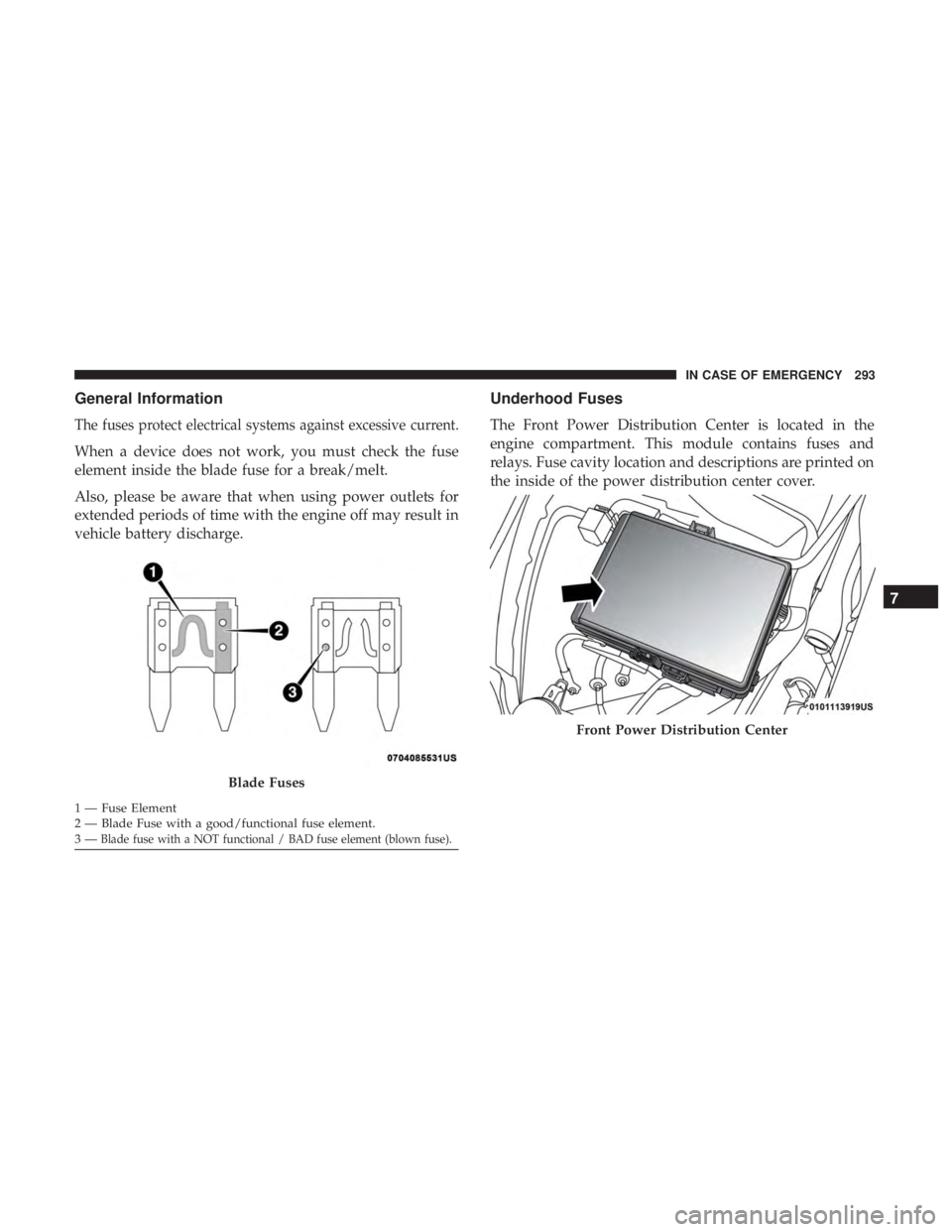
The fuses protect electrical systems against excessive current.
When a device does not work, you must check the fuse
element inside the blade fuse for a break/melt.
Also, please be aware that when using power outlets for
extended periods of time with the engine off may result in
vehicle battery discharge.
Underhood Fuses
The Front Power Distribution Center is located in the
engine compartment. This module contains fuses and
relays. Fuse cavity location and descriptions are printed on
the inside of the power distribution center cover.
Blade Fuses
1 — Fuse Element
2 — Blade Fuse with a good/functional fuse element.
3—
Blade fuse with a NOT functional / BAD fuse element (blown fuse).
Front Power Distribution Center
7
IN CASE OF EMERGENCY 293
Page 301 of 496
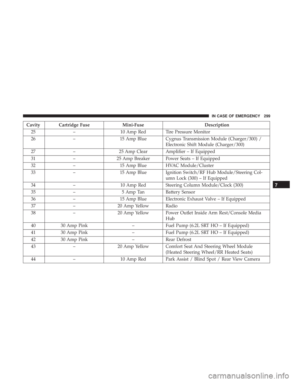
Cavity Cartridge FuseMini-FuseDescription
25 – 10 Amp Red Tire Pressure Monitor
26 – 15 Amp Blue Cygnus Transmission Module (Charger/300) /
Electronic Shift Module (Charger/300)
27 – 25 Amp Clear Amplifier – If Equipped
31 – 25 Amp Breaker Power Seats – If Equipped
32 – 15 Amp Blue HVAC Module/Cluster
33 – 15 Amp Blue Ignition Switch/RF Hub Module/Steering Col-
umn Lock (300) – If Equipped
34 – 10 Amp Red Steering Column Module/Clock (300)
35 – 5 Amp Tan Battery Sensor
36 – 15 Amp Blue Electronic Exhaust Valve – If Equipped
37 – 20 Amp Yellow Radio
38 – 20 Amp Yellow Power Outlet Inside Arm Rest/Console Media
Hub
40 30 Amp Pink –Fuel Pump (6.2L SRT HO – If Equipped)
41 30 Amp Pink –Fuel Pump (6.2L SRT HO – If Equipped)
42 30 Amp Pink –Rear Defrost
43 – 20 Amp Yellow Comfort Seat And Steering Wheel Module
(Heated Steering Wheel/RR Heated Seats)
44 – 10 Amp Red Park Assist / Blind Spot / Rear View Camera
7
IN CASE OF EMERGENCY 299
Page 319 of 496
5. Remove the Speed Limit sticker from the instrumentpanel after the tire has been repaired.
6. Replace the Sealant Bottle (4) and Sealant Hose (3) assembly at an authorized dealer as soon as possible.
Refer to “(F) Sealant Bottle And Hose Replacement”.
NOTE: When having the tire serviced, advise the autho-
rized dealer or service center that the tire has been sealed
using the Tire Service Kit.
(F) Sealant Bottle And Hose Replacement:
1. Uncoil the Sealant Hose (3) (clear in color).
2. Locate the red colored round Sealant Bottle release button at the lower right hand corner of the kit.
3. Push and hold the Sealant Bottle release button, then pull out the bottle holding the button.
4.
Clean any remaining sealant from the Tire Service Kit
housing.
5. Position the new Sealant Bottle (4) in the housing so that the Sealant Hose (3) aligns with the hose slot in the front
of the housing. Push and hold the Sealant Bottle release
button, then push the bottle into the housing by holding
the button. An audible click will be heard indicating the
bottle is locked into place. Release the button. 6. Verify that the cap is installed on the fitting at the end of
the Sealant Hose (3) and return the hose to its storage
area (located on top of the housing).
7. Return the Tire Service Kit to its storage location in the vehicle.
JUMP STARTING
If your vehicle has a discharged battery, it can be jump
started using a set of jumper cables and a battery in another
vehicle, or by using a portable battery booster pack. Jump
starting can be dangerous if done improperly, so please
follow the procedures in this section carefully.
WARNING!
Do not attempt jump starting if the battery is frozen. It
could rupture or explode and cause personal injury.
CAUTION!
Do not use a portable battery booster pack or any other
booster source with a system voltage greater than
12 Volts or damage to the battery, starter motor, alter-
nator or electrical system may occur.
7
IN CASE OF EMERGENCY 317