2019 DODGE CHARGER SRT mirror
[x] Cancel search: mirrorPage 66 of 496

Daytime Running Lights (DRL) — If Equipped
The Daytime Running Lights will turn on when the engine
is started and will remain on unless the headlamps are
turned to the on position, the parking brake is applied, or
the engine is shut OFF.
NOTE:If allowed by law in the country in which the
vehicle was purchased, the Daytime Running Lights can be
turned on and off using the Uconnect System, refer to
“Uconnect Settings” in “Multimedia” for further informa-
tion.
High/Low Beam Switch
Push the multifunction lever away from you to switch the
headlights to high beam. Pull the multifunction lever
toward you to switch the headlights back to low beam.
Automatic High Beam — If Equipped
The Automatic High Beam Headlamp Control system
provides increased forward lighting at night by automat-
ing high beam control through the use of a digital camera
mounted on the inside rearview mirror. This camera de-
tects vehicle specific light and automatically switches from
high beams to low beams until the approaching vehicle is
out of view. NOTE:
•
The Automatic High Beam Headlamp Control can be
turned on or off by selecting “ON” under “Auto High
Beam” within your Uconnect settings, as well as turning
the headlight switch to the AUTO position. Refer to
“Uconnect Settings” in “Multimedia” for further infor-
mation.
• Broken, muddy, or obstructed headlights and taillights
of vehicles in the field of view will cause headlights to
remain on longer (closer to the vehicle). Also, dirt, film,
and other obstructions on the windshield or camera lens
will cause the system to function improperly.
If the windshield or Automatic High Beam Headlamp
Control mirror is replaced, the mirror must be re-aimed to
ensure proper performance. See a local authorized dealer.
To Activate
1. Turn the headlight switch to the AUTO headlight posi- tion.
2. Push the multifunction lever away from you (toward front of vehicle) to engage the high beam mode.
NOTE: This system will not activate until the vehicle is at
or above 15 mph (24 km/h).
64 GETTING TO KNOW YOUR VEHICLE
Page 78 of 496
IconDescription
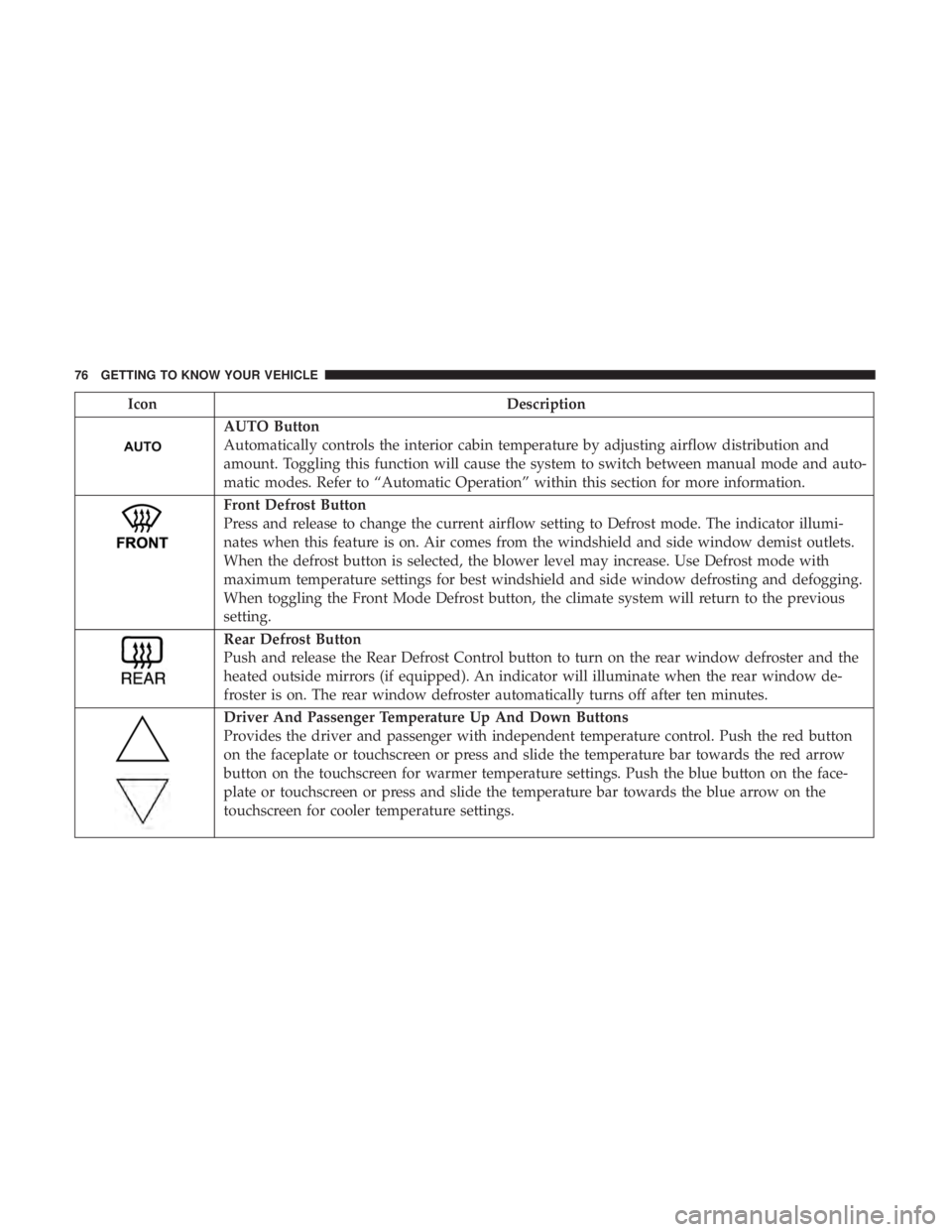
AUTO Button
Automatically controls the interior cabin temperature by adjusting airflow distribution and
amount. Toggling this function will cause the system to switch between manual mode and auto-
matic modes. Refer to “Automatic Operation” within this section for more information.
Front Defrost Button
Press and release to change the current airflow setting to Defrost mode. The indicator illumi-
nates when this feature is on. Air comes from the windshield and side window demist outlets.
When the defrost button is selected, the blower level may increase. Use Defrost mode with
maximum temperature settings for best windshield and side window defrosting and defogging.
When toggling the Front Mode Defrost button, the climate system will return to the previous
setting.
Rear Defrost Button
Push and release the Rear Defrost Control button to turn on the rear window defroster and the
heated outside mirrors (if equipped). An indicator will illuminate when the rear window de-
froster is on. The rear window defroster automatically turns off after ten minutes.
Driver And Passenger Temperature Up And Down Buttons
Provides the driver and passenger with independent temperature control. Push the red button
on the faceplate or touchscreen or press and slide the temperature bar towards the red arrow
button on the touchscreen for warmer temperature settings. Push the blue button on the face-
plate or touchscreen or press and slide the temperature bar towards the blue arrow on the
touchscreen for cooler temperature settings.
76 GETTING TO KNOW YOUR VEHICLE
Page 122 of 496
•If the menu is exited before the end of codes is reached
- when the driver re-enters the list will be restarted from
the beginning.
• When no codes are present or the last code is reached =
(P0000) and this message is displayed:
• “No or End of Diagnostic Codes.”
Battery Saver On/Battery Saver Mode Message —
Electrical Load Reduction Actions — If Equipped
This vehicle is equipped with an Intelligent Battery Sensor
(IBS) to perform additional monitoring of the electrical
system and status of the vehicle battery.
In cases when the IBS detects charging system failure, or
the vehicle battery conditions are deteriorating, electrical
load reduction actions will take place to extend the driving
time and distance of the vehicle. This is done by reducing
power to or turning off non-essential electrical loads.
Load reduction is only active when the engine is running.
It will display a message if there is a risk of battery
depletion to the point where the vehicle may stall due to
lack of electrical supply, or will not restart after the current
drive cycle. When load reduction is activated, the message “Battery
Saver On” or “Battery Saver Mode” will appear in the
instrument cluster.
These messages indicate the vehicle battery has a low state
of charge and continues to lose electrical charge at a rate
that the charging system cannot sustain.
NOTE:
•
The charging system is independent from load reduc-
tion. The charging system performs a diagnostic on the
charging system continuously.
• If the Battery Charge Warning Light is on it may indicate
a problem with the charging system. Refer to “Battery
Charge Warning Light” in “Getting To Know Your
Instrument Panel” for further information.
The electrical loads that may be switched off (if equipped),
and vehicle functions which can be affected by load
reduction:
• Heated Seat/Vented Seats/Heated Wheel
• Heated/Cooled Cup Holders — If Equipped
• Rear Defroster And Heated Mirrors
• HVAC System
120 GETTING TO KNOW YOUR INSTRUMENT PANEL
Page 150 of 496

AUXILIARY DRIVING SYSTEMS
Blind Spot Monitoring (BSM) — If Equipped
The Blind Spot Monitoring (BSM) system uses two radar
sensors, located inside the rear bumper fascia, to detect
highway licensable vehicles (automobiles, trucks, motor-
cycles, etc.) that enter the blind spot zones from the
rear/front/side of the vehicle.
When the vehicle is started, the BSM warning light will
momentarily illuminate in both outside rear view mirrors
to let the driver know that the system is operational.The BSM system sensors operate when the vehicle is in any
forward gear or REVERSE.
The BSM detection zone covers approximately one lane
width on both sides of the vehicle 12 ft (3.8 m). The zone
length starts at the outside rear view mirror and extends
approximately 10 ft (3 m) beyond the rear bumper of the
vehicle. The BSM system monitors the detection zones on
both sides of the vehicle when the vehicle speed reaches
approximately 6 mph (10 km/h) or higher and will alert
the driver of vehicles in these areas.
Rear Detection Zones
BSM Warning Light
148 SAFETY
Page 151 of 496
NOTE:
•The BSM system does NOT alert the driver about
rapidly approaching vehicles that are outside the detec-
tion zones.
• The BSM system detection zone DOES NOT change if
your vehicle is towing a trailer. Therefore, visually verify
the adjacent lane is clear for both your vehicle and trailer
before making a lane change. If the trailer or other object
(i.e., bicycle, sports equipment) extends beyond the side
of your vehicle, this may result in the BSM warning light
remaining illuminated the entire time the vehicle is in a
forward gear.
• The Blind Spot Monitoring (BSM) system may experi-
ence drop outs (blinking on and off) of the side mirror
Warning Indicator lamps when a motorcycle or any
small object remains at the side of the vehicle for
extended periods of time (more than a couple of sec-
onds).
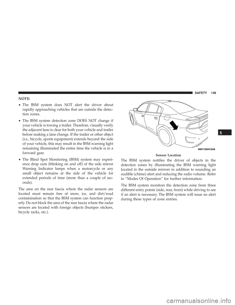
The area on the rear fascia where the radar sensors are
located must remain free of snow, ice, and dirt/road
contamination so that the BSM system can function prop-
erly. Do not block the area of the rear fascia where the radar
sensors are located with foreign objects (bumper stickers,
bicycle racks, etc.). The BSM system notifies the driver of objects in the
detection zones by illuminating the BSM warning light
located in the outside mirrors in addition to sounding an
audible (chime) alert and reducing the radio volume. Refer
to “Modes Of Operation” for further information.
The BSM system monitors the detection zone from three
different entry points (side, rear, front) while driving to see
if an alert is necessary. The BSM system will issue an alert
during these types of zone entries.
Sensor Location
5
SAFETY 149
Page 154 of 496
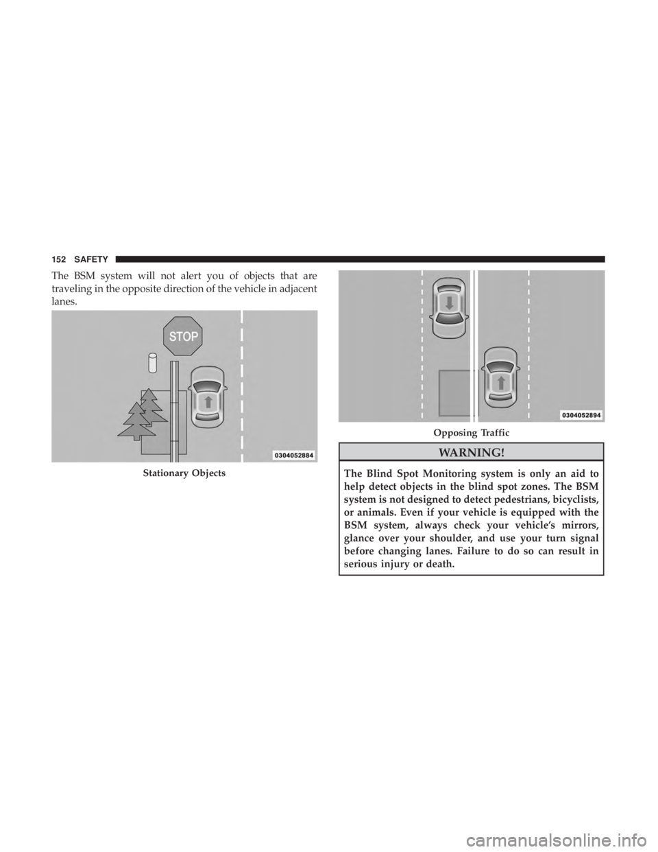
The BSM system will not alert you of objects that are
traveling in the opposite direction of the vehicle in adjacent
lanes.
WARNING!
The Blind Spot Monitoring system is only an aid to
help detect objects in the blind spot zones. The BSM
system is not designed to detect pedestrians, bicyclists,
or animals. Even if your vehicle is equipped with the
BSM system, always check your vehicle’s mirrors,
glance over your shoulder, and use your turn signal
before changing lanes. Failure to do so can result in
serious injury or death.Stationary Objects
Opposing Traffic
152 SAFETY
Page 156 of 496

Modes Of Operation
Three selectable modes of operation are available in the
Uconnect System. Refer to “Uconnect Settings” in “Multi-
media” for further information.
Blind Spot Alert Lights Only
When operating in Blind Spot Alert mode, the BSM system
will provide a visual alert in the appropriate side view
mirror based on a detected object. However, when the
system is operating in Rear Cross Path mode, the system
will respond with both visual and audible alerts when a
detected object is present. Whenever an audible alert is
requested, the radio volume is reduced so that the alert can
be better heard.
Blind Spot Alert Lights/Chime
When operating in Blind Spot Alert Lights/Chime mode,
the BSM system will provide a visual alert in the appro-
priate side view mirror based on a detected object. If the
turn signal is then activated, and it corresponds to an alertpresent on that side of the vehicle, an audible chime will
also be sounded. Whenever a turn signal and detected
object are present on the same side at the same time, both
the visual and audio alerts will be issued. In addition to the
audible alert the radio (if on) volume will be reduced so
that the alert can be better heard.
When the system is in RCP, the system shall respond with
both visual and audible alerts when a detected object is
present. Whenever an audible alert is requested, the radio
volume is reduced so that the alert can be better heard.
Blind Spot Alert Off
When the BSM system is turned off there will be no visual
or audible alerts from either the BSM or RCP systems.
NOTE:
The BSM system will store the current operating
mode when the vehicle is shut off. Each time the vehicle is
started the previously stored mode will be recalled and
used.
154 SAFETY
Page 214 of 496
STARTING THE ENGINE
Before starting your vehicle, adjust your seat, adjust the
inside and outside mirrors, fasten your seat belt, and if
present, instruct all other occupants to buckle their seat
belts.
WARNING!
•When exiting the vehicle, always make sure the
ignition is in “OFF” mode, remove the key fob from
the vehicle and lock the vehicle.
• Never leave children alone in a vehicle, or with
access to an unlocked vehicle. Leaving children in a
vehicle unattended is dangerous for a number of
reasons. A child or others could be seriously or
fatally injured. Children should be warned not to
touch the parking brake, brake pedal or the trans-
mission gear selector.
• Do not leave the key fob in or near the vehicle (or in
a location accessible to children), and do not leave
the ignition (of a vehicle equipped with Keyless
Enter-N-Go) in the ACC or ON/RUN mode. A child
could operate power windows, other controls, or
move the vehicle.
(Continued)
WARNING! (Continued)
•Do not leave children or animals inside parked
vehicles in hot weather. Interior heat build-up may
cause serious injury or death.
Automatic Transmission
The gear selector must be in the PARK position before you
can start the engine. Apply the brakes before shifting into
any driving gear.
CAUTION!
Damage to the transmission may occur if the following
precautions are not observed:
• Shift into or out of PARK or REVERSE only after the
vehicle has come to a complete stop.
• Do not shift between PARK, REVERSE, NEUTRAL,
or DRIVE when the engine is above idle speed.
• Before shifting into any gear, make sure your foot is
firmly pressing the brake pedal.
212 STARTING AND OPERATING