Page 298 of 496
Cavity Cartridge Fuse Mini-FuseDescription
30 – – Fuse – Spare
31 –25 Amp Clear Engine Module
32 – – Fuse – Spare
33 – – Fuse – Spare
34 –25 Amp Clear Powertrain #1
35 –20 Amp Yellow Powertrain #2
36 –10 Amp Red Anti-Lock Brake Module / Steering Column Lock
Module (300 if equipped)
37 –10 Amp Red Engine Controller / Rad Fan Relays (Charger/300) /
Electric Power Steering Module (Charger/300) /5-Speed TCM
38 –10 Amp Red Airbag Module
39 –10 Amp Red EPS (Challenger) / EHPS (Police) / AC Clutch Relay /
Vacuum Pump Relay / Rad Fan Relays (Challenger)
48 –10 Amp Red AWD Module / Front Axle Disconnect – If Equipped
49 – – Fuse – Spare
50 – – Fuse – Spare
51 –20 Amp Yellow Vacuum Pump
52 –5 Amp Tan Adaptive Cruise – If Equipped
53 – – Fuse – Spare
296 IN CASE OF EMERGENCY
Page 300 of 496
Cavity Cartridge FuseMini-FuseDescription
5 30 Amp Pink
20 Amp Blue – Police –
Sunroof/Dome Lamp – Police
6 40 Amp Green –Exterior Lighting #1
7 40 Amp Green –Exterior Lighting #2
8 30 Amp Pink –Interior Lighting
9 40 Amp Green –Power Locks
10 30 Amp Pink –Driver Door Control Module
11 30 Amp Pink –Passenger Door Control Module
12 – 20 Amp Yellow Dual USB Center Console Rear/Cigar Lighter IP
– If Equipped
15 40 Amp Green –HVAC Blower
16 20 Amp Blue –Left Spot Lamp – Police
17 20 Amp Blue –Right Spot Lamp – Police
18 30 Amp Pink –Mod Network Interface – Police
19 – –Fuse – Spare
20 – –Fuse – Spare
21 30 Amp Pink –Fuel Pump (Non 6.2L SRT HO)
22 – 5 Amp Tan Cyber Gateway Mod
23 – 10 Amp Red Fuel Door – If Equipped/Diagnostic Port
24 – 10 Amp Red Integrated Center Stack
298 IN CASE OF EMERGENCY
Page 301 of 496
Cavity Cartridge FuseMini-FuseDescription
25 – 10 Amp Red Tire Pressure Monitor
26 – 15 Amp Blue Cygnus Transmission Module (Charger/300) /
Electronic Shift Module (Charger/300)
27 – 25 Amp Clear Amplifier – If Equipped
31 – 25 Amp Breaker Power Seats – If Equipped
32 – 15 Amp Blue HVAC Module/Cluster
33 – 15 Amp Blue Ignition Switch/RF Hub Module/Steering Col-
umn Lock (300) – If Equipped
34 – 10 Amp Red Steering Column Module/Clock (300)
35 – 5 Amp Tan Battery Sensor
36 – 15 Amp Blue Electronic Exhaust Valve – If Equipped
37 – 20 Amp Yellow Radio
38 – 20 Amp Yellow Power Outlet Inside Arm Rest/Console Media
Hub
40 30 Amp Pink –Fuel Pump (6.2L SRT HO – If Equipped)
41 30 Amp Pink –Fuel Pump (6.2L SRT HO – If Equipped)
42 30 Amp Pink –Rear Defrost
43 – 20 Amp Yellow Comfort Seat And Steering Wheel Module
(Heated Steering Wheel/RR Heated Seats)
44 – 10 Amp Red Park Assist / Blind Spot / Rear View Camera
7
IN CASE OF EMERGENCY 299
Page 311 of 496

5. Remove the Speed Limit sticker from the instrumentpanel after the tire has been repaired.
6. Replace the Sealant Bottle (1) and Sealant Hose (6) assembly at an authorized dealer as soon as possible.
Refer to “(F) Sealant Bottle And Hose Replacement”.
NOTE: When having the tire serviced, advise the autho-
rized dealer or service center that the tire has been sealed
using the Tire Service Kit.
(F) Sealant Bottle And Hose Replacement:
1. Uncoil the Sealant Hose (6) (clear in color).
2. Locate the round Sealant Bottle release button in the recessed area under the sealant bottle.
3. Push the Sealant Bottle release button. The Sealant Bottle (1) will pop up. Remove the bottle and dispose of it
accordingly.
4. Clean any remaining sealant from the Tire Service Kit housing. 5. Position the new Sealant Bottle (1) in the housing so that
the Sealant Hose (6) aligns with the hose slot in the front
of the housing. Push the bottle into the housing. An
audible click will be heard indicating the bottle is locked
into place.
6. Verify that the cap is installed on the fitting at the end of the Sealant Hose (6) and return the hose to its storage
area (located on the bottom of the air pump).
7. Return the Tire Service Kit to its storage location in the vehicle.TIRE SERVICE KIT — IF EQUIPPED
Small punctures up to 1/4 inch (6 mm) in the tire tread can
be sealed with Tire Service Kit. Foreign objects (e.g., screws
or nails) should not be removed from the tire. Tire Service
Kit can be used in outside temperatures down to approxi-
mately -4°F (-20°C).
This kit will provide a temporary tire seal, allowing you to
drive your vehicle up to 100 miles (160 km) with a
maximum speed of 50 mph (80 km/h).
7
IN CASE OF EMERGENCY 309
Page 319 of 496

5. Remove the Speed Limit sticker from the instrumentpanel after the tire has been repaired.
6. Replace the Sealant Bottle (4) and Sealant Hose (3) assembly at an authorized dealer as soon as possible.
Refer to “(F) Sealant Bottle And Hose Replacement”.
NOTE: When having the tire serviced, advise the autho-
rized dealer or service center that the tire has been sealed
using the Tire Service Kit.
(F) Sealant Bottle And Hose Replacement:
1. Uncoil the Sealant Hose (3) (clear in color).
2. Locate the red colored round Sealant Bottle release button at the lower right hand corner of the kit.
3. Push and hold the Sealant Bottle release button, then pull out the bottle holding the button.
4.
Clean any remaining sealant from the Tire Service Kit
housing.
5. Position the new Sealant Bottle (4) in the housing so that the Sealant Hose (3) aligns with the hose slot in the front
of the housing. Push and hold the Sealant Bottle release
button, then push the bottle into the housing by holding
the button. An audible click will be heard indicating the
bottle is locked into place. Release the button. 6. Verify that the cap is installed on the fitting at the end of
the Sealant Hose (3) and return the hose to its storage
area (located on top of the housing).
7. Return the Tire Service Kit to its storage location in the vehicle.
JUMP STARTING
If your vehicle has a discharged battery, it can be jump
started using a set of jumper cables and a battery in another
vehicle, or by using a portable battery booster pack. Jump
starting can be dangerous if done improperly, so please
follow the procedures in this section carefully.
WARNING!
Do not attempt jump starting if the battery is frozen. It
could rupture or explode and cause personal injury.
CAUTION!
Do not use a portable battery booster pack or any other
booster source with a system voltage greater than
12 Volts or damage to the battery, starter motor, alter-
nator or electrical system may occur.
7
IN CASE OF EMERGENCY 317
Page 324 of 496
Follow these steps to use the Manual Park Release:
1. Firmly apply the parking brake.
2. Remove the console storage bin.
3. Remove the plastic cover under the bin by using the slotprovided to access the Manual Park Release lever.
4. Using a small screwdriver or similar tool, fish the tether strap up through the opening in the console base.
5. Press and maintain firm pressure on the brake pedal. 6. Insert the screwdriver into the slot in the center of the
lever, and disengage the lever locking tab by pushing it
to the right.
7. While holding the locking tab in the disengaged posi- tion, pull the tether strap to rotate the lever up and
rearward, until it locks in place in the vertical position.
The vehicle is now out of PARK and can be moved.
Release the parking brake only when the vehicle is
securely connected to a tow vehicle.
Console Storage Bin
Locking Tab
322 IN CASE OF EMERGENCY
Page 325 of 496

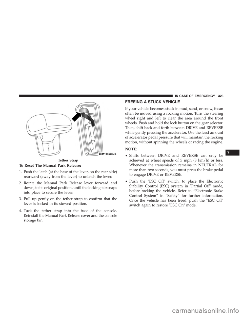
To Reset The Manual Park Release:
1. Push the latch (at the base of the lever, on the rear side)rearward (away from the lever) to unlatch the lever.
2. Rotate the Manual Park Release lever forward and down, to its original position, until the locking tab snaps
into place to secure the lever.
3. Pull up gently on the tether strap to confirm that the lever is locked in its stowed position.
4. Tuck the tether strap into the base of the console. Reinstall the Manual Park Release cover and the console
storage bin.
FREEING A STUCK VEHICLE
If your vehicle becomes stuck in mud, sand, or snow, it can
often be moved using a rocking motion. Turn the steering
wheel right and left to clear the area around the front
wheels. Push and hold the lock button on the gear selector.
Then, shift back and forth between DRIVE and REVERSE
while gently pressing the accelerator. Use the least amount
of accelerator pedal pressure that will maintain the rocking
motion, without spinning the wheels or racing the engine.
NOTE:
•Shifts between DRIVE and REVERSE can only be
achieved at wheel speeds of 5 mph (8 km/h) or less.
Whenever the transmission remains in NEUTRAL for
more than two seconds, you must press the brake pedal
to engage DRIVE or REVERSE.
• Push the �ESC Off� switch, to place the Electronic
Stability Control (ESC) system in �Partial Off�mode,
before rocking the vehicle. Refer to “Electronic Brake
Control System” in “Safety” for further information.
Once the vehicle has been freed, push the �ESC Off�
switch again to restore �ESC On�mode.
Tether Strap
7
IN CASE OF EMERGENCY 323
Page 345 of 496

•Noise (objectionable squeal, squeak, or rumble is heard
or felt while drive belt is in operation)
Some conditions can be caused by a faulty component such
as a belt pulley. Belt pulleys should be carefully inspected
for damage and proper alignment.
Belt replacement on some models requires the use of
special tools, we recommend having your vehicle serviced
at an authorized dealer.
Body Lubrication
Locks and all body pivot points, including such items as
seat tracks, door hinge pivot points and rollers, liftgate,
tailgate, decklid, sliding doors and hood hinges, should be
lubricated periodically with a lithium based grease, such as
Mopar Spray White Lube to assure quiet, easy operation
and to protect against rust and wear. Prior to the applica-
tion of any lubricant, the parts concerned should be wiped
clean to remove dust and grit; after lubricating excess oil
and grease should be removed. Particular attention should
also be given to hood latching components to ensure
proper function. When performing other underhood ser-
vices, the hood latch, release mechanism and safety catch
should be cleaned and lubricated. The external lock cylinders should be lubricated twice a
year, preferably in the Fall and Spring. Apply a small
amount of a high quality lubricant, such as Mopar Lock
Cylinder Lubricant directly into the lock cylinder.
Windshield Wiper Blades
Clean the rubber edges of the wiper blades and the
windshield periodically with a sponge or soft cloth and a
mild nonabrasive cleaner. This will remove accumulations
of salt or road film.
Operation of the wipers on dry glass for long periods may
cause deterioration of the wiper blades. Always use washer
fluid when using the wipers to remove salt or dirt from a
dry windshield.
Avoid using the wiper blades to remove frost or ice from
the windshield. Keep the blade rubber out of contact with
petroleum products such as engine oil, gasoline, etc.
NOTE:
Life expectancy of wiper blades varies depending
on geographical area and frequency of use. Poor perfor-
mance of blades may be present with chattering, marks,
water lines or wet spots. If any of these conditions are
present, clean the wiper blades or replace as necessary.
8
SERVICING AND MAINTENANCE 343