2019 DODGE CHARGER SRT lock
[x] Cancel search: lockPage 226 of 496
NOTE:After selecting any gear range, wait a moment to
allow the selected gear to engage before accelerating. This
is especially important when the engine is cold.
PARK (P)
This range supplements the parking brake by locking the
transmission. The engine can be started in this range.
Never attempt to use PARK while the vehicle is in motion.
Apply the parking brake when exiting the vehicle in this
range.
When parking on a level surface, you may shift the
transmission into PARK first, and then apply the parking
brake.
When parking on a hill, apply the parking brake before
shifting the transmission to PARK. As an added precau-
tion, turn the front wheels toward the curb on a downhill
grade and away from the curb on an uphill grade.
When exiting the vehicle, always:
• Apply the parking brake.
• Shift the transmission into PARK.
• Turn the ignition OFF.
• Remove the key fob from the vehicle.WARNING!
•Never use the PARK position as a substitute for the
parking brake. Always apply the parking brake fully
when exiting the vehicle to guard against vehicle
movement and possible injury or damage.
• Your vehicle could move and injure you and others if
it is not in PARK. Check by trying to move the
transmission gear selector out of PARK with the
brake pedal released. Make sure the transmission is
in PARK before exiting the vehicle.
• The transmission may not engage PARK if the ve-
hicle is moving. Always bring the vehicle to a
complete stop before shifting to PARK, and verify
that the transmission gear position indicator solidly
indicates PARK (P) without blinking. Ensure that the
vehicle is completely stopped, and the PARK posi-
tion is properly indicated, before exiting the vehicle.
• It is dangerous to shift out of PARK or NEUTRAL if
the engine speed is higher than idle speed. If your
foot is not firmly pressing the brake pedal, the
vehicle could accelerate quickly forward or in re-
verse. You could lose control of the vehicle and hit
someone or something. Only shift into gear when the
(Continued)
224 STARTING AND OPERATING
Page 227 of 496
WARNING!(Continued)
engine is idling normally and your foot is firmly
pressing the brake pedal.
• Unintended movement of a vehicle could injure
those in or near the vehicle. As with all vehicles, you
should never exit a vehicle while the engine is
running. Before exiting a vehicle, always come to a
complete stop, then apply the parking brake, shift
the transmission into PARK, and turn the ignition
OFF. When the ignition is in the OFF mode, the
transmission is locked in PARK, securing the vehicle
against unwanted movement.
• When exiting the vehicle, always make sure the
ignition is in the OFF mode, remove the key fob from
the vehicle, and lock the vehicle.
• Never leave children alone in a vehicle, or with
access to an unlocked vehicle. Allowing children to
be in a vehicle unattended is dangerous for a number
of reasons. A child or others could be seriously or
fatally injured. Children should be warned not to
touch the parking brake, brake pedal or the trans-
mission gear selector.
(Continued)
WARNING! (Continued)
•Do not leave the key fob in or near the vehicle (or in a
location accessible to children), and do not leave the
ignition in the ACC or ON/RUN mode. A child could
operate power windows, other controls, or move the
vehicle.
CAUTION!
•Before moving the transmission gear selector out of
PARK, you must start the engine, and also press the
brake pedal. Otherwise, damage to the gear selector
could result.
• DO NOT race the engine when shifting from PARK
or NEUTRAL into another gear range, as this can
damage the drivetrain.
The following indicators should be used to ensure that you
have properly engaged the transmission into the PARK posi-
tion:
• Look at the transmission gear position display and
verify that it indicates the PARK position (P), and is not
blinking.
• With the brake pedal released, verify that the gear
selector will not move out of PARK.
6
STARTING AND OPERATING 225
Page 245 of 496
To Set A Desired ACC Speed
When the vehicle reaches the speed desired, push the SET
(+)button or the SET (-)button and release. The instrument
cluster display will display the set speed.
If the system is set when the vehicle speed is below 20 mph
(32 km/h), the set speed shall be defaulted to 20 mph
(32 km/h). If the system is set when the vehicle speed is
above 20 mph (32 km/h), the set speed shall be the current
speed of the vehicle.
NOTE: ACC cannot be set if there is a stationary vehicle in
front of your vehicle in close proximity.
Remove your foot from the accelerator pedal. If you do not,
the vehicle may continue to accelerate beyond the set
speed. If this occurs:
• The message “DRIVER OVERRIDE” will display in the
instrument cluster display.
• The system will not be controlling the distance between
your vehicle and the vehicle ahead. The vehicle speed
will only be determined by the position of the accelera-
tor pedal.
To Cancel
The following conditions cancel the system:
• The brake pedal is applied.
• The CANC button is pushed.
• An Anti-Lock Brake System (ABS) event occurs.
• The gear selector is removed from the DRIVE position.
• The braking temperature exceeds normal range (over-
heated).
• The Electronic Stability Control/Traction Control Sys-
tem (ESC/TCS) activates.
• The vehicle parking brake is applied.
• Driver seatbelt is unbuckled at low speeds.
• Driver door is opened at low speeds.
• The driver switches ESC to full-off mode.
NOTE: If your vehicle stays at standstill for longer than
two seconds, then the system will cancel and the brake
force will be ramped-out. The driver will have to apply the
brakes to keep the vehicle at a standstill.
6
STARTING AND OPERATING 243
Page 254 of 496

NOTE:
•If the “ACC/FCW Unavailable Wipe Front Radar Sen-
sor” message occurs frequently (e.g. more than once on
every trip) without any snow, rain, mud, or other
obstruction, have the radar sensor realigned at your
authorized dealer.
• Installing a snow plow, front-end protector, an aftermar-
ket grille or modifying the grille is not recommended.
Doing so may block the sensor and inhibit ACC/FCW
operation.
“Clean Front Windshield” Warning
The “ACC/FCW Limited Functionality Clean Front Wind-
shield” warning will display and also a chime will indicate
when conditions temporarily limit system performance.
This most often occurs at times of poor visibility, such as in
snow or heavy rain and fog. The ACC system may also
become temporarily blinded due to obstructions, such as
mud, dirt, or ice on windshield and fog on the inside of
glass. In these cases, the instrument cluster display will
display “ACC/FCW Limited Functionality Clean Front
Windshield” and the system will have degraded perfor-
mance. The “ACC/FCW Limited Functionality Clean Front Wind-
shield” message can sometimes be displayed while driving
in adverse weather conditions. The ACC/FCW system will
recover after the vehicle has left these areas. Under rare
conditions, when the camera is not tracking any vehicles or
objects in its path this warning may temporarily occur.
If weather conditions are not a factor, the driver should
examine the windshield and the camera located on the
back side of the inside rear view mirror. They may require
cleaning or removal of an obstruction.
When the condition that created limited functionality is no
longer present, the system will return to full functionality.
NOTE:
If the “ACC/FCW Limited Functionality Clean
Front Windshield” message occurs frequently (e.g. more
than once on every trip) without any snow, rain, mud, or
other obstruction, have the windshield and forward facing
camera inspected at your authorized dealer.
252 STARTING AND OPERATING
Page 272 of 496
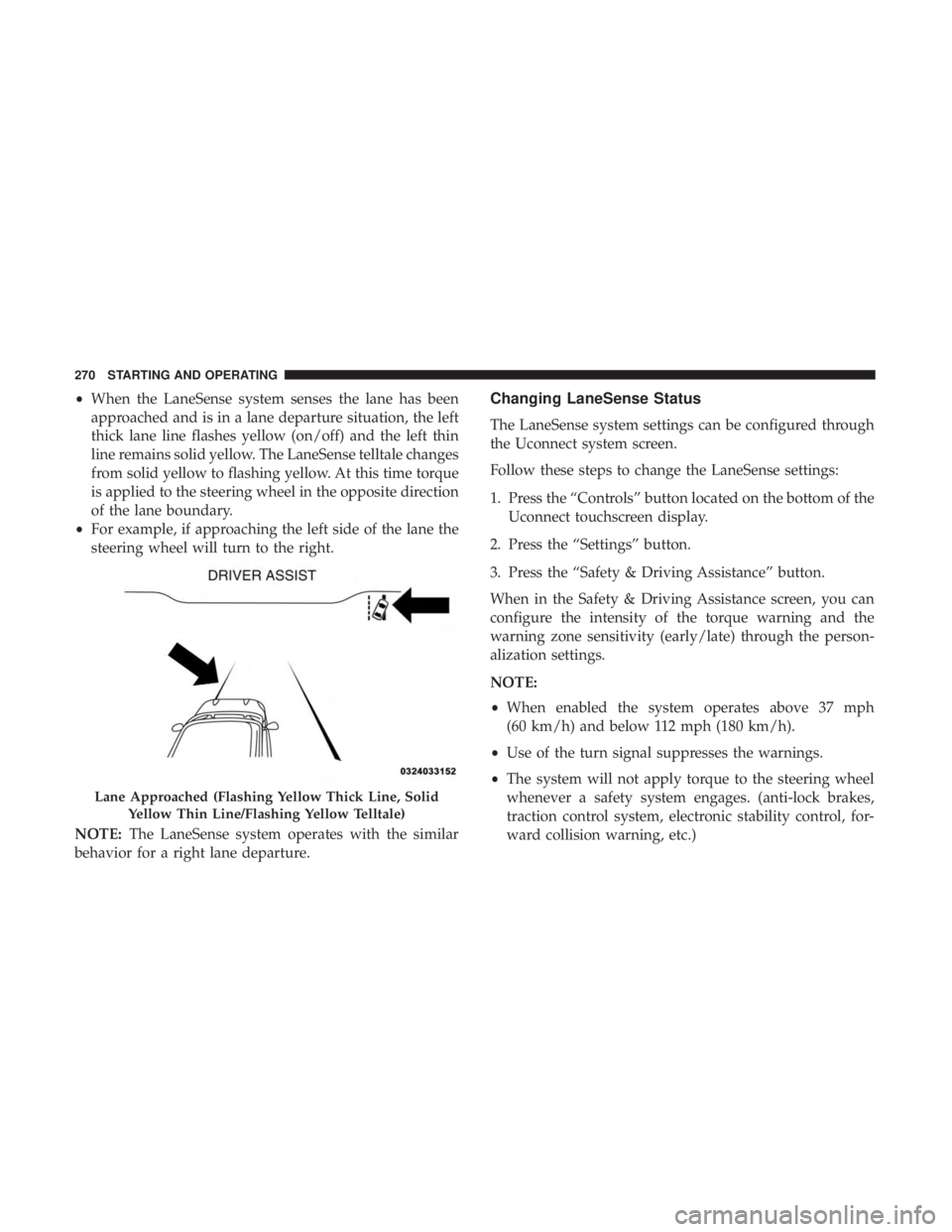
•When the LaneSense system senses the lane has been
approached and is in a lane departure situation, the left
thick lane line flashes yellow (on/off) and the left thin
line remains solid yellow. The LaneSense telltale changes
from solid yellow to flashing yellow. At this time torque
is applied to the steering wheel in the opposite direction
of the lane boundary.
• For example, if approaching the left side of the lane the
steering wheel will turn to the right.
NOTE: The LaneSense system operates with the similar
behavior for a right lane departure.Changing LaneSense Status
The LaneSense system settings can be configured through
the Uconnect system screen.
Follow these steps to change the LaneSense settings:
1. Press the “Controls” button located on the bottom of the Uconnect touchscreen display.
2. Press the “Settings” button.
3. Press the “Safety & Driving Assistance” button.
When in the Safety & Driving Assistance screen, you can
configure the intensity of the torque warning and the
warning zone sensitivity (early/late) through the person-
alization settings.
NOTE:
• When enabled the system operates above 37 mph
(60 km/h) and below 112 mph (180 km/h).
• Use of the turn signal suppresses the warnings.
• The system will not apply torque to the steering wheel
whenever a safety system engages. (anti-lock brakes,
traction control system, electronic stability control, for-
ward collision warning, etc.)
Lane Approached (Flashing Yellow Thick Line, Solid
Yellow Thin Line/Flashing Yellow Telltale)
270 STARTING AND OPERATING
Page 282 of 496
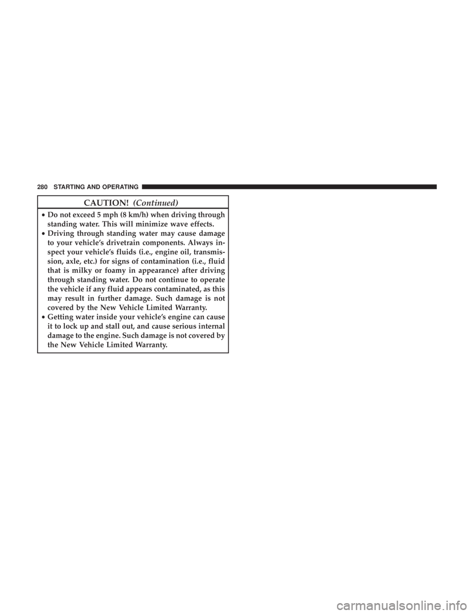
CAUTION!(Continued)
•Do not exceed 5 mph (8 km/h) when driving through
standing water. This will minimize wave effects.
• Driving through standing water may cause damage
to your vehicle’s drivetrain components. Always in-
spect your vehicle’s fluids (i.e., engine oil, transmis-
sion, axle, etc.) for signs of contamination (i.e., fluid
that is milky or foamy in appearance) after driving
through standing water. Do not continue to operate
the vehicle if any fluid appears contaminated, as this
may result in further damage. Such damage is not
covered by the New Vehicle Limited Warranty.
• Getting water inside your vehicle’s engine can cause
it to lock up and stall out, and cause serious internal
damage to the engine. Such damage is not covered by
the New Vehicle Limited Warranty.
280 STARTING AND OPERATING
Page 293 of 496
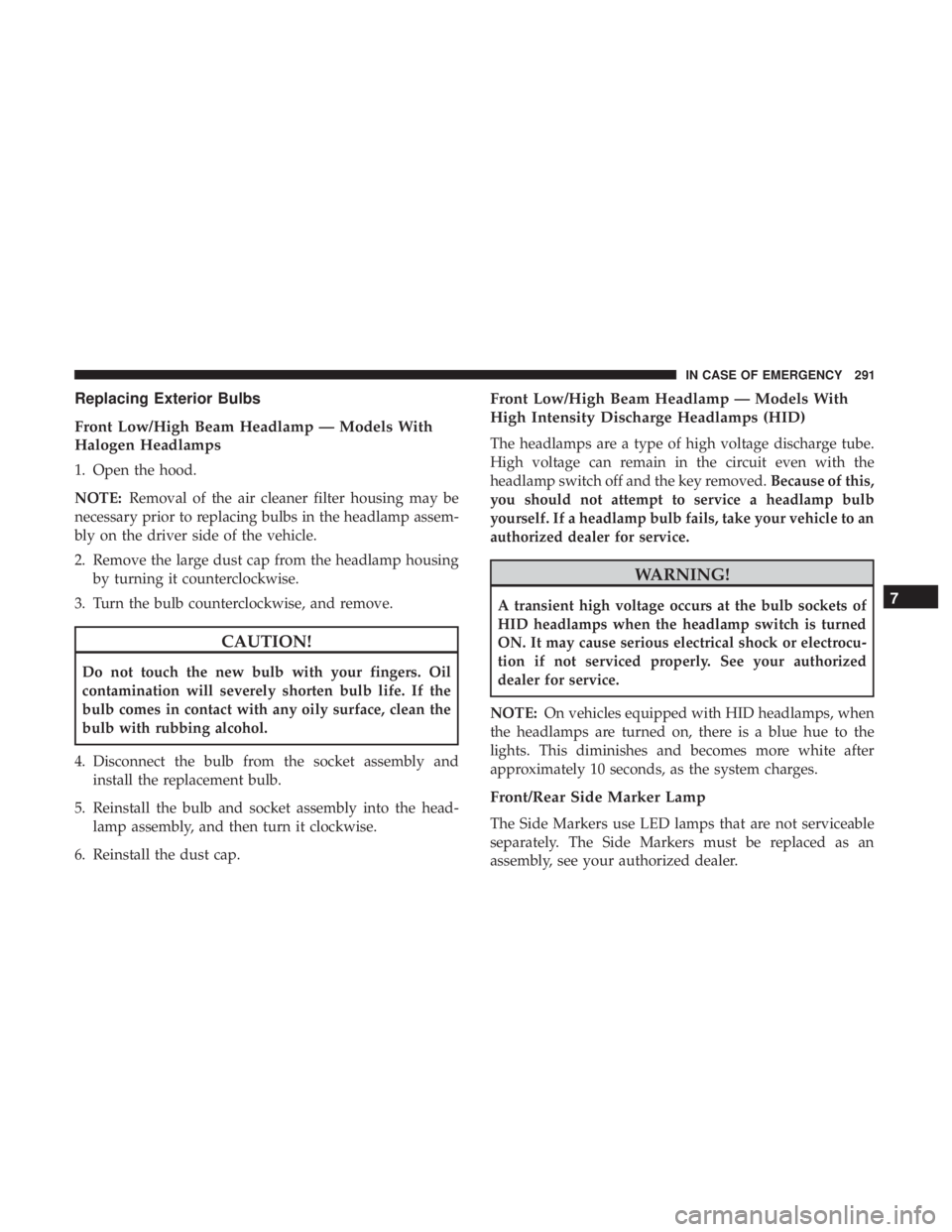
Replacing Exterior Bulbs
Front Low/High Beam Headlamp — Models With
Halogen Headlamps
1. Open the hood.
NOTE:Removal of the air cleaner filter housing may be
necessary prior to replacing bulbs in the headlamp assem-
bly on the driver side of the vehicle.
2. Remove the large dust cap from the headlamp housing by turning it counterclockwise.
3. Turn the bulb counterclockwise, and remove.
CAUTION!
Do not touch the new bulb with your fingers. Oil
contamination will severely shorten bulb life. If the
bulb comes in contact with any oily surface, clean the
bulb with rubbing alcohol.
4. Disconnect the bulb from the socket assembly and install the replacement bulb.
5. Reinstall the bulb and socket assembly into the head- lamp assembly, and then turn it clockwise.
6. Reinstall the dust cap.
Front Low/High Beam Headlamp — Models With
High Intensity Discharge Headlamps (HID)
The headlamps are a type of high voltage discharge tube.
High voltage can remain in the circuit even with the
headlamp switch off and the key removed. Because of this,
you should not attempt to service a headlamp bulb
yourself. If a headlamp bulb fails, take your vehicle to an
authorized dealer for service.
WARNING!
A transient high voltage occurs at the bulb sockets of
HID headlamps when the headlamp switch is turned
ON. It may cause serious electrical shock or electrocu-
tion if not serviced properly. See your authorized
dealer for service.
NOTE: On vehicles equipped with HID headlamps, when
the headlamps are turned on, there is a blue hue to the
lights. This diminishes and becomes more white after
approximately 10 seconds, as the system charges.
Front/Rear Side Marker Lamp
The Side Markers use LED lamps that are not serviceable
separately. The Side Markers must be replaced as an
assembly, see your authorized dealer.
7
IN CASE OF EMERGENCY 291
Page 296 of 496
CAUTION!
•When installing the power distribution center cover,
it is important to ensure the cover is properly posi-
tioned and fully latched. Failure to do so may allow
water to get into the power distribution center and
possibly result in an electrical system failure.
(Continued)
CAUTION! (Continued)
•When replacing a blown fuse, it is important to use
only a fuse having the correct amperage rating. The
use of a fuse with a rating other than indicated may
result in a dangerous electrical system overload. If a
properly rated fuse continues to blow, it indicates a
problem in the circuit that must be corrected.
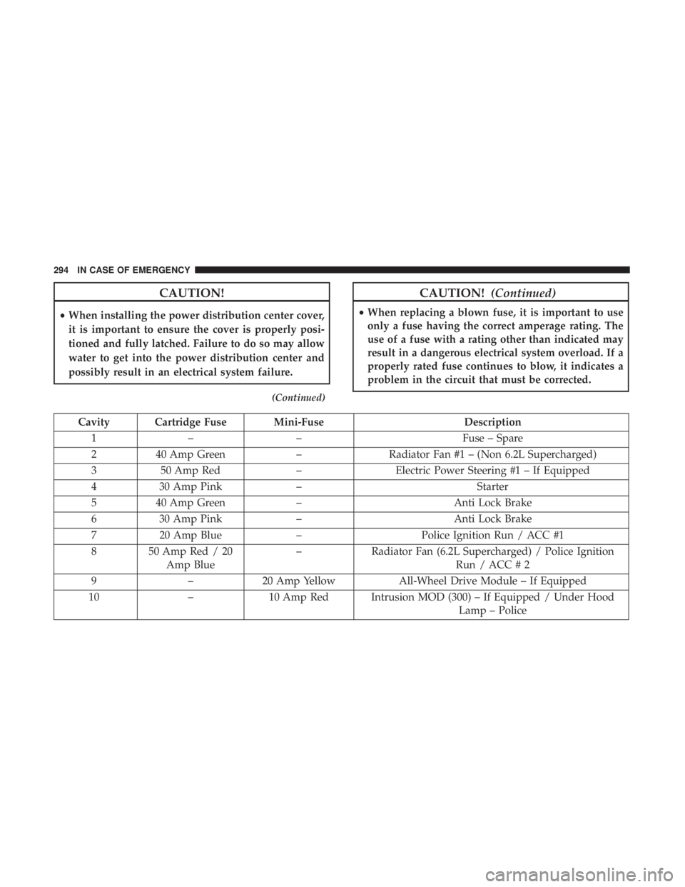
Cavity Cartridge Fuse Mini-Fuse Description
1 – – Fuse – Spare
2 40 Amp Green –Radiator Fan #1 – (Non 6.2L Supercharged)
3 50 Amp Red –Electric Power Steering #1 – If Equipped
4 30 Amp Pink – Starter
5 40 Amp Green – Anti Lock Brake
6 30 Amp Pink – Anti Lock Brake
7 20 Amp Blue –Police Ignition Run / ACC #1
8 50 Amp Red / 20 Amp Blue –
Radiator Fan (6.2L Supercharged) / Police Ignition
Run / ACC # 2
9 –20 Amp Yellow All-Wheel Drive Module – If Equipped
10 –10 Amp Red Intrusion MOD (300) – If Equipped / Under Hood
Lamp – Police
294 IN CASE OF EMERGENCY