2019 DODGE CHARGER clock
[x] Cancel search: clockPage 64 of 560

MIRRORS
Inside Day/Night Mirror — If Equipped
A single ball joint mirror is provided in the vehicle. It is a
twist on mirror that has a fixed position at the windshield.
The mirror installs on the windshield button with a coun-
terclockwise rotation and requires no tools for mounting.
The mirror head can be adjusted up, down, left, and right
for various drivers. The mirror should be adjusted to center
on the view through the rear window.
Headlight glare from vehicles behind you can be reduced
by moving the small control under the mirror to the night
position (toward the rear of the vehicle). The mirror should
be adjusted while the small control under the mirror is set
in the day position (toward the windshield).
Automatic Dimming Mirror — If Equipped
The mirror head can be adjusted up, down, left, and right
for various drivers. The mirror should be adjusted to center
on the view through the rear window.
This mirror automatically adjusts for headlight glare from
vehicles behind you.
NOTE:The Automatic Dimming feature is disabled when
the vehicle is in REVERSE to improve rear view viewing.
Adjusting Rearview Mirror
62 GETTING TO KNOW YOUR VEHICLE
Page 68 of 560

“Slide-On-Rod” And Extender Features Of Sun
Visor
To use the “Slide-On-Rod” feature of the sun visor, rotate
the sun visor downward and swing the sun visor so it is
parallel to the side window, grab the sun visor and pull
rearwards until the sun visor is in the desired position. To
use the extender feature of the sun visor, grab the extender
which is located at the rear of the visor and pull rearward.
EXTERIOR LIGHTS
Headlight Switch
The headlight switch is located on the left side of the
instrument panel. This switch controls the operation of the
headlights, parking lights, instrument panel lights, instru-
ment panel light dimming, interior lights and fog lights.
Rotate the headlight switch clockwise to the first detent for
parking light and instrument panel light operation. Rotate
the headlight switch to the second detent for headlight,
parking light and instrument panel light operation. Push
the switch to enable fog lights (if equipped).
Slide-On-Rod Feature
Headlight Switch
66 GETTING TO KNOW YOUR VEHICLE
Page 71 of 560

Automatic Headlights
This system automatically turns the headlights on or off
according to ambient light levels. To turn the system on,
rotate the headlight switch counterclockwise to the AUTO
position. When the system is on, the headlight time delay
feature is also on. This means the headlights will stay on
for up to 90 seconds after you place the ignition into the
OFF position. The headlight time delay can be pro-
grammed 0/30/60/90 seconds.
Refer to “Uconnect Settings” in “Multimedia” for further
information.
To turn the automatic system off, move the headlight
switch out of the AUTO position.
NOTE:The engine must be running before the headlights
will come on in the automatic mode.
Parking Lights
Turn the headlight switch knob to the first detent to turn
the parking lights on. This also turns on all instrument
panel lighting.
Headlights On With Wipers
When this feature is active, the headlights will turn on after
the wipers are turned on if the headlight switch is placed in
the AUTO position and programmable feature is set to on.
In addition, the headlights will turn off when the wipers
are turned off if they were turned on by this feature.
NOTE: The “Headlights On With Wipers” feature can be
turned on or off using the Uconnect System. Refer to
“Uconnect Settings” in “Multimedia” for further informa-
tion.
Headlight Time Delay
This feature provides the safety of headlight illumination
for up to 90 seconds when leaving your vehicle in an unlit
area with the headlight switch in the O (off) position.
To activate the delay feature, turn OFF the ignition switch
while the headlights are still on. Then, turn off the head-
lights within 45 seconds. The delay interval begins when
the headlight switch is turned off.
3
GETTING TO KNOW YOUR VEHICLE 69
Page 85 of 560

IconDescription
Faceplate Knob
Touchscreen Buttons
Blower Control
Blower Control is used to regulate the amount of air forced through the climate system. There
are seven blower speeds available. The speeds can be selected using either the blower control
knob on the faceplate or the buttons on the touchscreen.
• Faceplate: The blower speed increases as you turn the blower control knob clockwise from
the lowest blower setting. The blower speed decreases as you turn the blower control knob
counterclockwise.
• Touchscreen: Use the small blower icon to reduce the blower setting and the large blower
icon to increase the blower setting. Blower can also be selected by pressing the blower bar
area between the icons.
Mode Control Select Mode by pressing one of the Mode buttons on the touchscreen to change the airflow dis-
tribution mode. The airflow distribution mode can be adjusted so air comes from the instrument
panel outlets, floor outlets, defrost outlets and demist outlets. The Mode settings are as follows:
Panel Mode
Panel Mode
Air comes from the outlets in the instrument panel. Each of these outlets can be individually
adjusted to direct the flow of air. The air vanes of the center outlets and outboard outlets can be
moved up and down or side to side to regulate airflow direction. There is a shut off wheel lo-
cated below the air vanes to shut off or adjust the amount of airflow from these outlets.
3
GETTING TO KNOW YOUR VEHICLE 83
Page 91 of 560

IconDescription
SYNC Button
Press the SYNC button on the touchscreen to toggle the Sync feature on/off. The SYNC indica-
tor is illuminated when this feature is enabled. SYNC is used to synchronize the passenger
temperature setting with the driver temperature setting. Changing the passenger temperature
setting while in Sync will automatically exit this feature.
NOTE:The SYNC button is only available on the touchscreen.
Faceplate Knob
Touchscreen Buttons
Blower Control
Blower Control is used to regulate the amount of air forced through the climate system. There
are seven blower speeds available. The speeds can be selected using either the blower control
knob on the faceplate or the buttons on the touchscreen.
• Faceplate: The blower speed increases as you turn the blower control knob clockwise from
the lowest blower setting. The blower speed decreases as you turn the blower control knob
counterclockwise.
• Touchscreen: Use the small blower icon to reduce the blower setting and the large blower
icon to increase the blower setting. Blower can also be selected by pressing the blower bar
area between the icons.
Panel ModePanel Mode
Air comes from the outlets in the instrument panel. Each of these outlets can be individually
adjusted to direct the flow of air. The air vanes of the center outlets and outboard outlets can be
moved up and down or side to side to regulate airflow direction. There is a shut off wheel
located below the air vanes to shut off or adjust the amount of airflow from these outlets.
3
GETTING TO KNOW YOUR VEHICLE 89
Page 316 of 560

Replacing Exterior Bulbs
Front Low/High Beam Headlamp — Models With
Halogen Headlamps
1. Open the hood.
NOTE:Removal of the air cleaner filter housing may be
necessary prior to replacing bulbs in the headlamp assem-
bly on the driver side of the vehicle.
2. Remove the large dust cap from the headlamp housing by turning it counterclockwise.
3. Turn the bulb counterclockwise, and remove.
CAUTION!
Do not touch the new bulb with your fingers. Oil
contamination will severely shorten bulb life. If the
bulb comes in contact with any oily surface, clean the
bulb with rubbing alcohol.
4. Disconnect the bulb from the socket assembly and install the replacement bulb.
5. Reinstall the bulb and socket assembly into the head- lamp assembly, and then turn it clockwise.
6. Reinstall the dust cap.
Front Low/High Beam Headlamp — Models With
High Intensity Discharge Headlamps (HID)
The headlamps are a type of high voltage discharge tube.
High voltage can remain in the circuit even with the
headlamp switch off and the key removed. Because of this,
you should not attempt to service a headlamp bulb
yourself. If a headlamp bulb fails, take your vehicle to an
authorized dealer for service.
WARNING!
A transient high voltage occurs at the bulb sockets of
HID headlamps when the headlamp switch is turned
ON. It may cause serious electrical shock or electrocu-
tion if not serviced properly. See your authorized
dealer for service.
NOTE: On vehicles equipped with HID headlamps, when
the headlamps are turned on, there is a blue hue to the
lights. This diminishes and becomes more white after
approximately 10 seconds, as the system charges.
Front/Rear Side Marker Lamp
The Side Markers use LED lamps that are not serviceable
separately. The Side Markers must be replaced as an
assembly, see your authorized dealer.
314 IN CASE OF EMERGENCY
Page 325 of 560

Cavity Cartridge FuseMini-FuseDescription
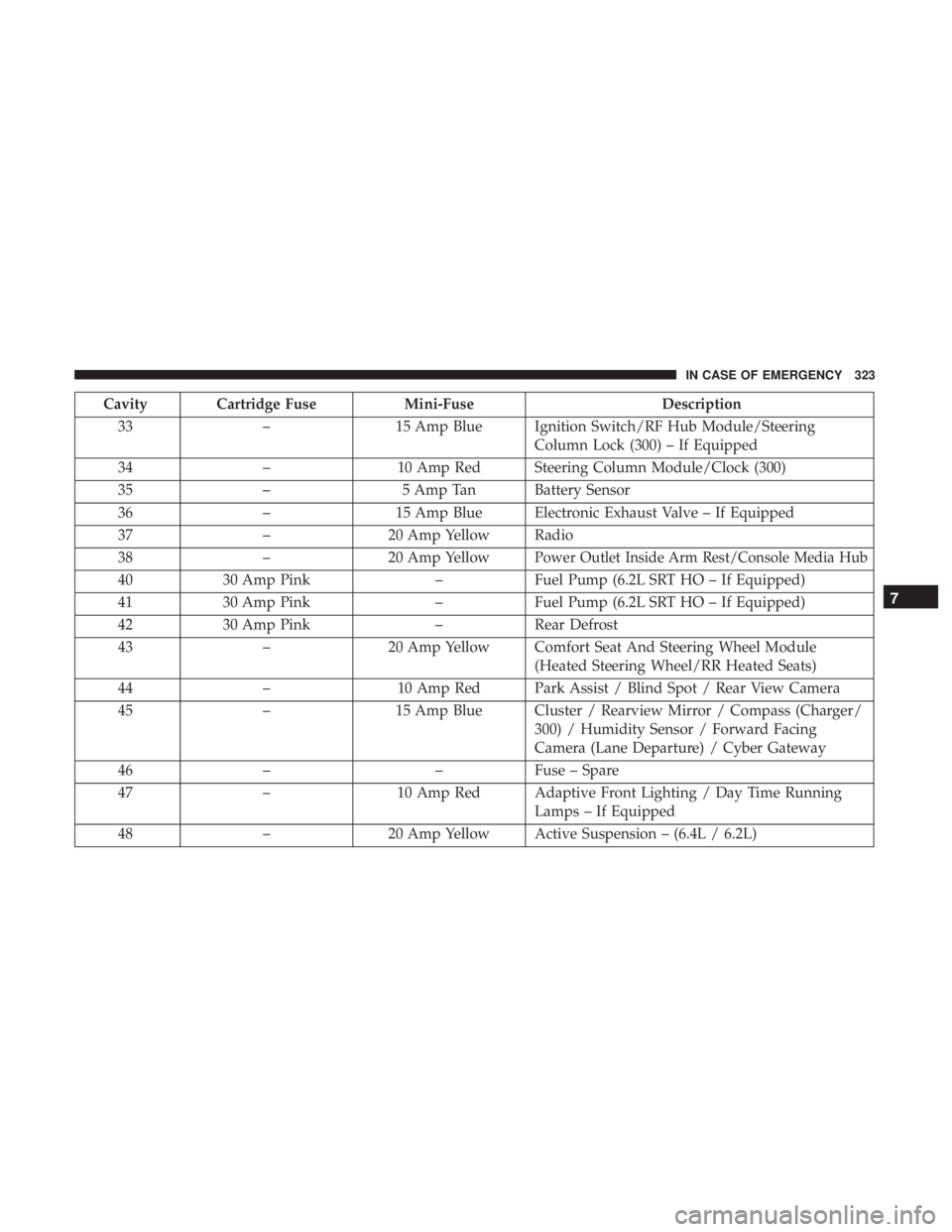
33 –15 Amp Blue Ignition Switch/RF Hub Module/Steering
Column Lock (300) – If Equipped
34 –10 Amp Red Steering Column Module/Clock (300)
35 –5 Amp Tan Battery Sensor
36 –15 Amp Blue Electronic Exhaust Valve – If Equipped
37 –20 Amp Yellow Radio
38 –20 Amp Yellow
Power Outlet Inside Arm Rest/Console Media Hub
4030 Amp Pink –Fuel Pump (6.2L SRT HO – If Equipped)
41 30 Amp Pink –Fuel Pump (6.2L SRT HO – If Equipped)
42 30 Amp Pink –Rear Defrost
43 –20 Amp Yellow Comfort Seat And Steering Wheel Module
(Heated Steering Wheel/RR Heated Seats)
44 –10 Amp Red Park Assist / Blind Spot / Rear View Camera
45 –15 Amp Blue Cluster / Rearview Mirror / Compass (Charger/
300) / Humidity Sensor / Forward Facing
Camera (Lane Departure) / Cyber Gateway
46 – –Fuse – Spare
47 –10 Amp Red Adaptive Front Lighting / Day Time Running
Lamps – If Equipped
48 –20 Amp Yellow Active Suspension – (6.4L / 6.2L)
7
IN CASE OF EMERGENCY 323
Page 328 of 560

Jack Location/Spare Tire Stowage
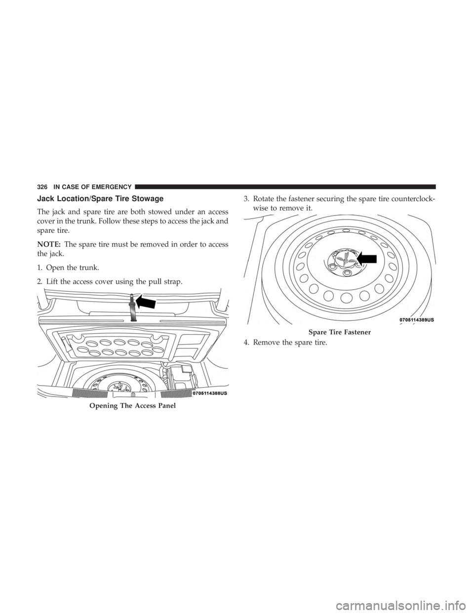
The jack and spare tire are both stowed under an access
cover in the trunk. Follow these steps to access the jack and
spare tire.
NOTE:The spare tire must be removed in order to access
the jack.
1. Open the trunk.
2. Lift the access cover using the pull strap. 3. Rotate the fastener securing the spare tire counterclock-
wise to remove it.
4. Remove the spare tire.
Opening The Access Panel
Spare Tire Fastener
326 IN CASE OF EMERGENCY