Page 113 of 560
General Information
The following regulatory statement applies to all Radio
Frequency (RF) devices equipped in this vehicle:
This device complies with Part 15 of the FCC Rules and
with Innovation, Science and Economic Development
Canada license-exempt RSS standard(s). Operation is sub-
ject to the following two conditions:
1. This device may not cause harmful interference, and
2. This device must accept any interference received, in-cluding interference that may cause undesired opera-
tion.
NOTE: Changes or modifications not expressly approved
by the party responsible for compliance could void the
user ’s authority to operate the equipment.
INTERNAL EQUIPMENT
Storage
Glove Compartment
The glove compartment is located on the passenger side of
the instrument panel.
To open the glove compartment, pull the release handle.
Glove Compartment
3
GETTING TO KNOW YOUR VEHICLE 111
Page 117 of 560

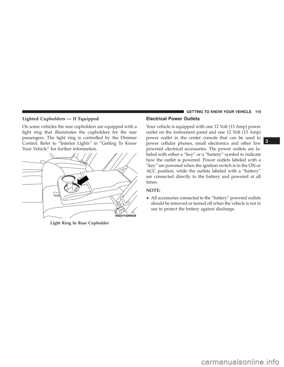
Lighted Cupholders — If Equipped
On some vehicles the rear cupholders are equipped with a
light ring that illuminates the cupholders for the rear
passengers. The light ring is controlled by the Dimmer
Control. Refer to “Interior Lights” in “Getting To Know
Your Vehicle” for further information.
Electrical Power Outlets
Your vehicle is equipped with one 12 Volt (13 Amp) power
outlet on the instrument panel and one 12 Volt (13 Amp)
power outlet in the center console that can be used to
power cellular phones, small electronics and other low
powered electrical accessories. The power outlets are la-
beled with either a “key” or a “battery” symbol to indicate
how the outlet is powered. Power outlets labeled with a
“key” are powered when the ignition switch is in the ON or
ACC position, while the outlets labeled with a “battery”
are connected directly to the battery and powered at all
times.
NOTE:
•
All accessories connected to the “battery” powered outlets
should be removed or turned off when the vehicle is not in
use to protect the battery against discharge.
Light Ring In Rear Cupholder
3
GETTING TO KNOW YOUR VEHICLE 115
Page 118 of 560
The front power outlet is located inside the storage area on
the center stack of the instrument panel.
WARNING!
Do not place ashes inside the cubby bin located on the
center console on vehicles not equipped with the ash
receiver tray. A fire leading to bodily injury could result.
In addition to the front power outlet, there is also a power
outlet located in the storage area of the center console.
NOTE:If the Media Hub is in use, do not exceed the
maximum power of 100 Watts (8 Amps) for the center
console power outlet. When the Media Hub is not in use,
the outlet can deliver up to 160 Watts (13 Amps). If the
power rating is exceeded, the fuse protecting the system
needs to be replaced.
Front Power OutletCenter Console Power Outlet
116 GETTING TO KNOW YOUR VEHICLE
Page 119 of 560

NOTE:The instrument panel power outlet and dual rear
console USB ports can be changed to “battery” powered all
the time by moving the #12 20 Amp fuse from “IGN” to
“B+”. Refer to “Fuses” in “In Case Of Emergency” for
further information.
WARNING!
To avoid serious injury or death:
• Only devices designed for use in this type of outlet
should be inserted into any 12 Volt outlet.
• Do not touch with wet hands.
• Close the lid when not in use and while driving the
vehicle.
• If this outlet is mishandled, it may cause an electric
shock and failure.
CAUTION!
• Many accessories that can be plugged in draw power
from the vehicle’s battery even when not in use (i.e.,
cellular phones, etc.). Eventually, if plugged in long
enough, the vehicle’s battery will discharge suffi-
ciently to degrade battery life and/or prevent the
engine from starting.
• Accessories that draw higher power (i.e., coolers,
vacuum cleaners, lights, etc.) will degrade the battery
even more quickly. Only use these intermittently and
with greater caution.
(Continued)
Power Outlet Fuse Locations
1 — #12 Fuse 20 Amp Yellow Instrument Panel Power Outlet/Dual
USB Charge Only Ports
2 — #38 Fuse 20 Amp Yellow Center Console Power Outlet/Media
Hub
3
GETTING TO KNOW YOUR VEHICLE 117
Page 123 of 560

GETTING TO KNOW YOUR INSTRUMENT PANEL
CONTENTS
�INSTRUMENT CLUSTER ..................122
▫ Instrument Cluster Descriptions ............125
� INSTRUMENT CLUSTER DISPLAY ...........126
▫ Location And Controls ...................126
▫ Engine Oil Life Reset ....................128
▫ Performance Shift Indicator (PSI) —
If Equipped .......................... .129
▫ Instrument Cluster Display Selectable Menu
Items .............................. .129
▫ Battery Saver On/Battery Saver Mode
Message — Electrical Load Reduction Actions —
If Equipped ......................... .134�
WARNING LIGHTS AND MESSAGES .........136
▫ Red Warning Lights .....................136
▫ Yellow Warning Lights ...................140
▫ Yellow Indicator Lights ...................145
▫ Green Indicator Lights ...................145
▫ White Indicator Lights ...................146
▫ Blue Indicator Lights ....................146
� ONBOARD DIAGNOSTIC SYSTEM — OBD II . . .147
▫ Onboard Diagnostic System (OBD II)
Cybersecurity ........................ .147
�
EMISSIONS INSPECTION AND MAINTENANCE
PROGRAMS ........................... .148
4
Page 124 of 560
INSTRUMENT CLUSTER
Instrument Cluster For 3.6L Engine
122 GETTING TO KNOW YOUR INSTRUMENT PANEL
Page 125 of 560
Instrument Cluster For 5.7L Engine
4
GETTING TO KNOW YOUR INSTRUMENT PANEL 123
Page 126 of 560
Instrument Cluster For 6.4L Engine
124 GETTING TO KNOW YOUR INSTRUMENT PANEL