2019 DODGE CHARGER audio
[x] Cancel search: audioPage 120 of 560

CAUTION!(Continued)
•After the use of high power draw accessories or long
periods of the vehicle not being started (with acces-
sories still plugged in), the vehicle must be driven a
sufficient length of time to allow the alternator to
recharge the vehicle’s battery.
• Power outlets are designed for accessory plugs only.
Do not hang any type of accessory or accessory
bracket from the plug. Improper use of the power
outlet can cause damage.
Wireless Charging Pad — If Equipped
Your vehicle may be equipped with an Open Dots compat-
ible wire-free phone charging surface located in the center
console. The wireless charger features continuous wireless
charging during vehicle operation and allows for uninter-
rupted Bluetooth streaming to properly equipped vehicle
audio systems. In order to enjoy the convenience of Open Dots wire-free
charging, you must obtain an aftermarket wireless-enabled
case and then install the case on your phone. Set the phone
on the wireless charging pad face up. The charging indi-
cator on your phone will light up indicating that your
phone is charging.
NOTE:
The charging pad is safe to the touch. However, if
metallic items are placed on the charging surface while in
use, the device will turn off. Clean all spills immediately
and allow to dry before using.
Wireless Charging Pad
118 GETTING TO KNOW YOUR VEHICLE
Page 129 of 560
•Audio
• Messages
• Screen Setup
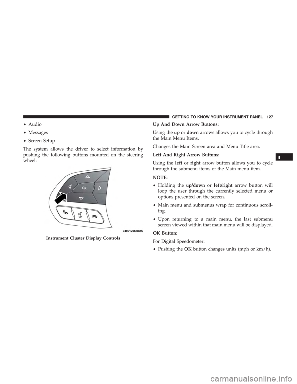
The system allows the driver to select information by
pushing the following buttons mounted on the steering
wheel: Up And Down Arrow Buttons:
Using the
upordown arrows allows you to cycle through
the Main Menu Items.
Changes the Main Screen area and Menu Title area.
Left And Right Arrow Buttons:
Using the leftorright arrow button allows you to cycle
through the submenu items of the Main menu item.
NOTE:
• Holding the up/downorleft/right arrow button will
loop the user through the currently selected menu or
options presented on the screen.
• Main menu and submenus wrap for continuous scroll-
ing.
• Upon returning to a main menu, the last submenu
screen viewed within that main menu will be displayed.
OK Button:
For Digital Speedometer:
• Pushing the OKbutton changes units (mph or km/h).
Instrument Cluster Display Controls
4
GETTING TO KNOW YOUR INSTRUMENT PANEL 127
Page 134 of 560
Trip Info
Push and release theupordown arrow button until the Trip
Menu item is displayed in the instrument cluster display.
Toggle the leftorright arrow button to select Trip A or Trip
B. The Trip information will display the following:
• Distance – Shows the total distance (mi or km) traveled
for Trip A or Trip B since the last reset.
• Average Fuel Economy – Shows the average fuel
economy (MPG, L/100km or km/L) of Trip A or Trip B
since the last reset.
• Elapsed Time – Shows the total elapsed time of travel
since the last reset.
Hold the OKbutton to reset feature information.
Audio
This menu displays the Audio information of the currently
playing audio source (e.g. FM radio).
Messages
This feature shows the number of stored warning mes-
sages, if any. Pushing the rightorleft arrow button will
allow you to scroll through the stored messages.
Screen Setup
Push and release the upordown arrow button until the
Screen Setup Menu displays in the instrument cluster
display. Push and release the OKbutton to enter the
submenus. The Screen Setup feature allows you to change
what information is displayed in the instrument cluster as
well as the location that information is displayed.
1. Upper Left
•Compass (default)
• Outside Temp.
• Time (default)
• Range to Empty (default)
• Average (MPG, L/100 km, or km/L)
• Current (MPG, L/100 km, or km/L)
• Trip A Distance
• Trip B Distance
• None
2. Upper Right •Compass
• Outside Temp (default)
• Time
132 GETTING TO KNOW YOUR INSTRUMENT PANEL
Page 135 of 560

•Range to Empty
• Average (MPG, L/100 km, or km/L)
• Current (MPG, L/100 km, or km/L)
• Trip A Distance
• Trip B Distance
• None
3. Center •Menu Title (default)
• Compass
• Outside Temp.
• Time
• Range to Empty
• Average (MPG, L/100 km, or km/L)
• Current (MPG, L/100 km, or km/L)
• Trip A Distance
• Trip B Distance
• Audio Information
• Digital Speed
• None 4. Current Gear
•On
• Off (default)
5. Odometer •Show (default)
• Hide
6. Gear Display •Full (default)
• Single
7. Restore Defaults •Ok
• Cancel
Diagnostics
This feature allows the driver to view engine and emission
vehicle faults.
• Push OKto have the most recent fault code sent.
•
There is a delay when the next diagnostic code is re-
quested during which the following message is displayed:
• “Checking System for Diagnostic Codes.”
• Driver must push the OKbutton again to see the next
Pcode otherwise current message remains displayed.
4
GETTING TO KNOW YOUR INSTRUMENT PANEL 133
Page 137 of 560
•HVAC System
• 115V AC Power Inverter System
• Audio and Telematics System
Loss of the battery charge may indicate one or more of the
following conditions:
• The charging system cannot deliver enough electrical
power to the vehicle system because the electrical loads
are larger than the capability of the charging system. The
charging system is still functioning properly.
• Turning on all possible vehicle electrical loads (e.g.
HVAC to max settings, exterior and interior lights,
overloaded power outlets +12V, 115V AC, USB ports)
during certain driving conditions (city driving, towing,
frequent stopping).
• Installing options like additional lights, upfitter electri-
cal accessories, audio systems, alarms and similar de-
vices.
• Unusual driving cycles (short trips separated by long
parking periods). •
The vehicle was parked for an extended period of time
(weeks, months).
• The battery was recently replaced and was not charged
completely.
• The battery was discharged by an electrical load left on
when the vehicle was parked.
• The battery was used for an extended period with the
engine not running to supply radio, lights, chargers,
+12V portable appliances like vacuum cleaners, game
consoles and similar devices.
What to do when an electrical load reduction action
message is present (“Battery Saver On” or “Battery Saver
Mode”)
During a trip:
• Reduce power to unnecessary loads if possible:
– Turn off redundant lights (interior or exterior)
– Check what may be plugged in to power outlets +12V, 115V AC, USB ports
– Check HVAC settings (blower, temperature)
– Check the audio settings (volume)
4
GETTING TO KNOW YOUR INSTRUMENT PANEL 135
Page 138 of 560
After a trip:
•Check if any aftermarket equipment was installed (ad-
ditional lights, upfitter electrical accessories, audio sys-
tems, alarms) and review specifications if any (load and
Ignition Off Draw currents).
• Evaluate the latest driving cycles (distance, driving time
and parking time).
• The vehicle should have service performed if the mes-
sage is still present during consecutive trips and the
evaluation of the vehicle and driving pattern did not
help to identify the cause.
WARNING LIGHTS AND MESSAGES
The warning/indicator lights will illuminate in the instru-
ment panel together with a dedicated message and/or
acoustic signal when applicable. These indications are
indicative and precautionary and as such must not be
considered as exhaustive and/or alternative to the infor-
mation contained in the Owner ’s Manual, which you are
advised to read carefully in all cases. Always refer to the
information in this chapter in the event of a failure indica-
tion. All active telltales will display first if applicable. The
system check menu may appear different based upon
equipment options and current vehicle status. Some tell-
tales are optional and may not appear.
Red Warning Lights
— Air Bag Warning Light
This warning light will illuminate to indicate a fault with
the air bag, and will turn on for four to eight seconds as a
bulb check when the ignition is placed in the ON/RUN or
ACC/ON/RUN position. This light will illuminate with a
single chime when a fault with the air bag has been
detected, it will stay on until the fault is cleared. If the light
is either not on during startup, stays on, or turns on while
driving, have the system inspected at an authorized dealer
as soon as possible.
— Brake Warning Light
This warning light monitors various brake functions, includ-
ing brake fluid level and parking brake application. If the
brake light turns on it may indicate that the parking brake is
applied, that the brake fluid level is low, or that there is a
problem with the anti-lock brake system reservoir.
If the light remains on when the parking brake has been
disengaged, and the fluid level is at the full mark on the
master cylinder reservoir, it indicates a possible brake
hydraulic system malfunction or that a problem with the
Brake Booster has been detected by the Anti-Lock Brake
System (ABS) / Electronic Stability Control (ESC) system.
136 GETTING TO KNOW YOUR INSTRUMENT PANEL
Page 170 of 560

the visual and audio alerts will be issued. In addition to the
audible alert the radio (if on) volume will be reduced so
that the alert can be better heard.
When the system is in RCP, the system shall respond with
both visual and audible alerts when a detected object is
present. Whenever an audible alert is requested, the radio
volume is reduced so that the alert can be better heard.
Blind Spot Alert Off
When the BSM system is turned off there will be no visual
or audible alerts from either the BSM or RCP systems.
NOTE:
The BSM system will store the current operating
mode when the vehicle is shut off. Each time the vehicle is
started the previously stored mode will be recalled and used.
General Information
The following regulatory statement applies to all Radio
Frequency (RF) devices equipped in this vehicle:
This device complies with Part 15 of the FCC Rules and
with Industry Canada license-exempt RSS standard(s).
Operation is subject to the following two conditions:
1. This device may not cause harmful interference. 2. This device must accept any interference received, in-
cluding interference that may cause undesired opera-
tion.
NOTE: Changes or modifications not expressly approved
by the party responsible for compliance could void the
user ’s authority to operate the equipment.
Forward Collision Warning (FCW) With Mitigation
Operation
The Forward Collision Warning (FCW) system with miti-
gation provides the driver with audible warnings, visual
warnings (within the instrument cluster display), and may
apply a brake jerk to warn the driver when it detects a
potential frontal collision. The warnings and limited brak-
ing are intended to provide the driver with enough time to
react, avoid or mitigate the potential collision.
NOTE: FCW monitors the information from the forward
looking sensors, as well as the Electronic Stability Control
(ESC) system, to calculate the probability of a forward
collision. When the system determines that a forward
collision is probable, the driver will be provided with
audible and visual warnings and may provide a brake jerk
168 SAFETY
Page 282 of 560
•When you move the gear selector to the REVERSE
position and ParkSense is turned off, the instrument
cluster display will show the “PARKSENSE OFF” mes-
sage for as long as the vehicle is in REVERSE.
• ParkSense will reduce the volume of the radio when it is
sounding an audio tone.
• Clean the ParkSense sensors regularly, taking care not to
scratch or damage them. The sensors must not be
covered with ice, snow, slush, mud, dirt or debris.
Failure to do so can result in the system not working
properly. The ParkSense system might not detect an
obstacle behind the fascia/bumper, or it could provide a
false indication that an obstacle is behind the fascia/
bumper.
• Ensure the ParkSense system is off if objects such as
bicycle carriers, trailer hitches, etc., are placed within
12 inches (30 cm) from the rear fascia/bumper. Failure to
do so can result in the system misinterpreting a close
object as a sensor problem, causing the “PARKSENSE
UNAVAILABLE SERVICE REQUIRED” message to be
shown in the instrument cluster display.WARNING!
Drivers must be careful when backing up even when
using the Rear Park Assist system. Always check
carefully behind your vehicle, and be sure to check for
pedestrians, animals, other vehicles, obstructions, or
blind spots before backing up. You are responsible for
the safety of your surroundings and must continue to
pay attention while backing up. Failure to do so can
result in serious injury or death.
CAUTION!
• ParkSense is only a parking aid and it is unable to
recognize every obstacle, including small obstacles.
Parking curbs might be temporarily detected or not
detected at all. Obstacles located above or below the
sensors will not be detected when they are in close
proximity.
•
The vehicle must be driven slowly when using
ParkSense in order to be able to stop in time when an
obstacle is detected. It is recommended that the driver
looks over his/her shoulder when using ParkSense.
280 STARTING AND OPERATING