2019 DODGE CHARGER instrument panel
[x] Cancel search: instrument panelPage 350 of 560
3. Uncoil the Air Pump Hose (5) (black in color) and screwthe fitting at the end of hose onto the valve stem.
4. Check the pressure in the tire by reading the Pressure Gauge (8).
If tire pressure is less than 19 psi (1.3 Bar):
The tire is too badly damaged. Do not attempt to drive the
vehicle further. Call for assistance.
If the tire pressure is 19 psi (1.3 Bar) or higher:
1. Push the Power Button (1) to turn on Tire Service Kit and inflate the tire to the pressure indicated on the tire
and loading information label on the driver-side door
opening.
NOTE: If the tire becomes over-inflated, push the Deflation
Button to reduce the tire pressure to the recommended
inflation pressure before continuing.
2. Disconnect the Tire Service Kit from the valve stem, reinstall the cap on the valve stem and unplug from
12 Volt outlet.
3. Place the Tire Service Kit in its proper storage area in the vehicle. 4. Have the tire inspected and repaired or replaced at the
earliest opportunity at an authorized dealer or tire
service center.
5. Remove the Speed Limit sticker from the instrument panel after the tire has been repaired.
6. Replace the Sealant Bottle (4) and Sealant Hose (3) assembly at an authorized dealer as soon as possible.
Refer to “(F) Sealant Bottle And Hose Replacement”.
NOTE: When having the tire serviced, advise the autho-
rized dealer or service center that the tire has been sealed
using the Tire Service Kit.
(F) Sealant Bottle And Hose Replacement:
1. Uncoil the Sealant Hose (3) (clear in color).
2. Locate the red colored round Sealant Bottle release button at the lower right hand corner of the kit.
3. Push and hold the Sealant Bottle release button, then pull out the bottle holding the button.
4. Clean any remaining sealant from the Tire Service Kit housing.
348 IN CASE OF EMERGENCY
Page 363 of 560
SCHEDULED SERVICING
3.6L And 5.7L Engines
Your vehicle is equipped with an automatic oil change
indicator system. The oil change indicator system will
remind you that it is time to take your vehicle in for
scheduled maintenance.
Based on engine operation conditions, the oil change
indicator message will illuminate. This means that service
is required for your vehicle. Operating conditions such as
frequent short-trips, trailer tow, extremely hot or cold
ambient temperatures, and E85 fuel usage will influence
when the “Change Oil” or “Oil Change Required” message
is displayed. Severe Operating Conditions can cause the
change oil message to illuminate as early as 3,500 miles
(5,600 km) since last reset. Have your vehicle serviced as
soon as possible, within the next 500 miles (800 km).
The “Oil Change Required” message will be displayed in
the instrument cluster and a single chime will sound,
indicating that an oil change is necessary.
Your authorized dealer will reset the oil change indicator
message after completing the scheduled oil change. If a
scheduled oil change is performed by someone other than
your authorized dealer, the message can be reset by referring
to “Instrument Cluster Display” in “Getting To Know Your
Instrument Panel” for further information.
NOTE:Under no circumstances should oil change inter-
vals exceed 10,000 miles (16,000 km), 12 months or
350 hours of engine run time, whichever comes first. The
350 hours of engine run or idle time is generally only a
concern for fleet customers.
Severe Duty All Models
Change Engine Oil at 4,000 miles (6,500 km) or 350 hours of
engine run time if the vehicle is operated in a dusty and
off-road environment, or is operated predominantly at idle
or only very low engine RPM’s. This type of vehicle use is
considered Severe Duty.
8
SERVICING AND MAINTENANCE 361
Page 367 of 560

Heavy Duty Use Of The Vehicle
Change engine oil at 4,000 miles (6,500 km) or 350 hours of
engine run time if the vehicle is operated in a dusty and off
road environment or is operated predominately at idle or
only very low engine RPM’s. This type of vehicle use is
considered Severe Duty.
6.4L Engine
The scheduled maintenance services listed in this manual
must be done at the times or mileages specified to protect
your vehicle warranty and ensure the best vehicle perfor-
mance and reliability. More frequent maintenance may be
needed for vehicles in severe operating conditions, such as
dusty areas and very short trip driving. Inspection and
service should also be done anytime a malfunction is
suspected.
The oil change indicator system will remind you that it is
time to take your vehicle in for scheduled maintenance.
A “Oil Change Required” message will be displayed in the
instrument cluster and a single chime will sound, indicat-
ing that an oil change is necessary.Based on engine operation conditions, the oil change
indicator message will illuminate. This means that service
is required for your vehicle. Have your vehicle serviced as
soon as possible, within the next 500 miles (800 km).
NOTE:
•
The oil change indicator message will not monitor the
time since the last oil change. Change your vehicle’s oil
if it has been six months since your last oil change, even
if the oil change indicator message is NOT illuminated.
• Change your engine oil more often if you drive your
vehicle off-road/track usage for an extended period of
time.
• Under no circumstances should oil change intervals
exceed 6,000 miles (10,000 km) or six months, whichever
comes first.
An authorized dealer will reset the oil change indicator
message after completing the scheduled oil change. If a
scheduled oil change is performed by someone other than
an authorized dealer, the message can be reset by referring
to the steps described under “Instrument Cluster Display”
in “Getting To Know Your Instrument Panel” for further
information.
8
SERVICING AND MAINTENANCE 365
Page 429 of 560

IDENTIFICATION DATA
Vehicle Identification Number
The Vehicle Identification Number (VIN) is on the left front
corner of the instrument panel. The VIN is visible from
outside of the vehicle through the windshield. This number
also appears on the Automobile Information Disclosure
Label affixed to a window on your vehicle, the vehicle
registration, and the title.The Vehicle Identification Number (VIN) is also located on
the right front strut tower inside the engine compartment.
NOTE:
It is illegal to remove or alter the VIN.
VIN Location
VIN Location
9
TECHNICAL SPECIFICATIONS 427
Page 447 of 560
•Routinely check www.driveuconnect.com (U.S. Resi-
dents) or www.driveuconnect.ca (Canadian Residents)
to learn about available Uconnect software updates.
• Only connect and use trusted media devices (e.g.
personal mobile phones, USBs, CDs).
Privacy of any wireless and wired communications cannot
be assured. Third parties may unlawfully intercept infor-
mation and private communications without your consent.
For further information, refer to “Data Collection & Pri-
vacy” in your Uconnect Owner ’s Manual Supplement or
“Onboard Diagnostic System (OBD II) Cybersecurity” in
“Getting To Know Your Instrument Panel”.
UCONNECT SETTINGS
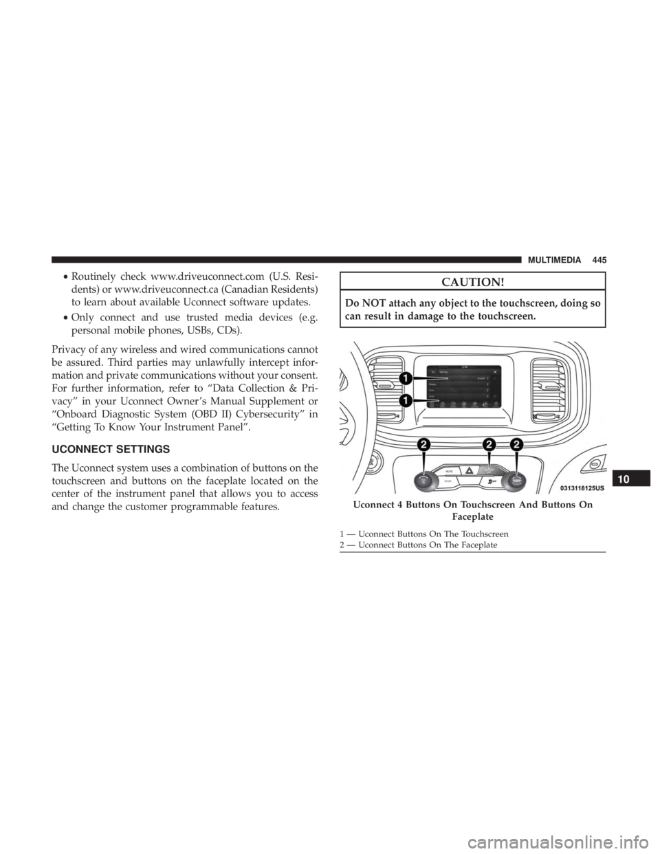
The Uconnect system uses a combination of buttons on the
touchscreen and buttons on the faceplate located on the
center of the instrument panel that allows you to access
and change the customer programmable features.
CAUTION!
Do NOT attach any object to the touchscreen, doing so
can result in damage to the touchscreen.
Uconnect 4 Buttons On Touchscreen And Buttons On Faceplate
1 — Uconnect Buttons On The Touchscreen
2 — Uconnect Buttons On The Faceplate
10
MULTIMEDIA 445
Page 500 of 560
Performance Control — If Equipped
Your vehicle is equipped with a Performance Control
feature which allows for coordinating the operation of
various vehicle systems depending upon the type of driv-
ing behavior desired. The Performance Control feature is
controlled through the Uconnect system and may be ac-
cessed by performing any of the following:
•Pushing the Super Track Pack button on the instrument
panel switch bank.
•
Selecting “Performance Control” from the “Apps” menu.
• Selecting “Performance Control” from within the Perfor-
mance Pages menu.
You will be able to enable, disable, and customize the
functionality of the Launch Control and Performance Con-
trol Set-Up features within Performance Control.
Descriptions of these features are provided below. To
access information about the functionality of these features
through the Uconnect system, press the “Info” button on
the touchscreen. NOTE:
Scat and Widebody Dodge vehicles equipped with
a 6.4L engine will use SRT Drive Modes rather than the
Dodge Performance Control Pages. Please refer to the
Owner ’s Manual Supplement for further information on
the SRT Drive Modes.
Launch Mode
WARNING!
Launch Mode is intended for off-highway or off-road
use only and should not be used on any public
roadways. It is recommended that this feature be used
in a controlled environment, and within the limits of
the law. The capabilities of the vehicle as measured by
the performance pages must never be exploited in a
reckless or dangerous manner, which can jeopardize
the user ’s safety or the safety of others. Only a safe,
attentive, and skillful driver can prevent accidents.
498 MULTIMEDIA
Page 504 of 560
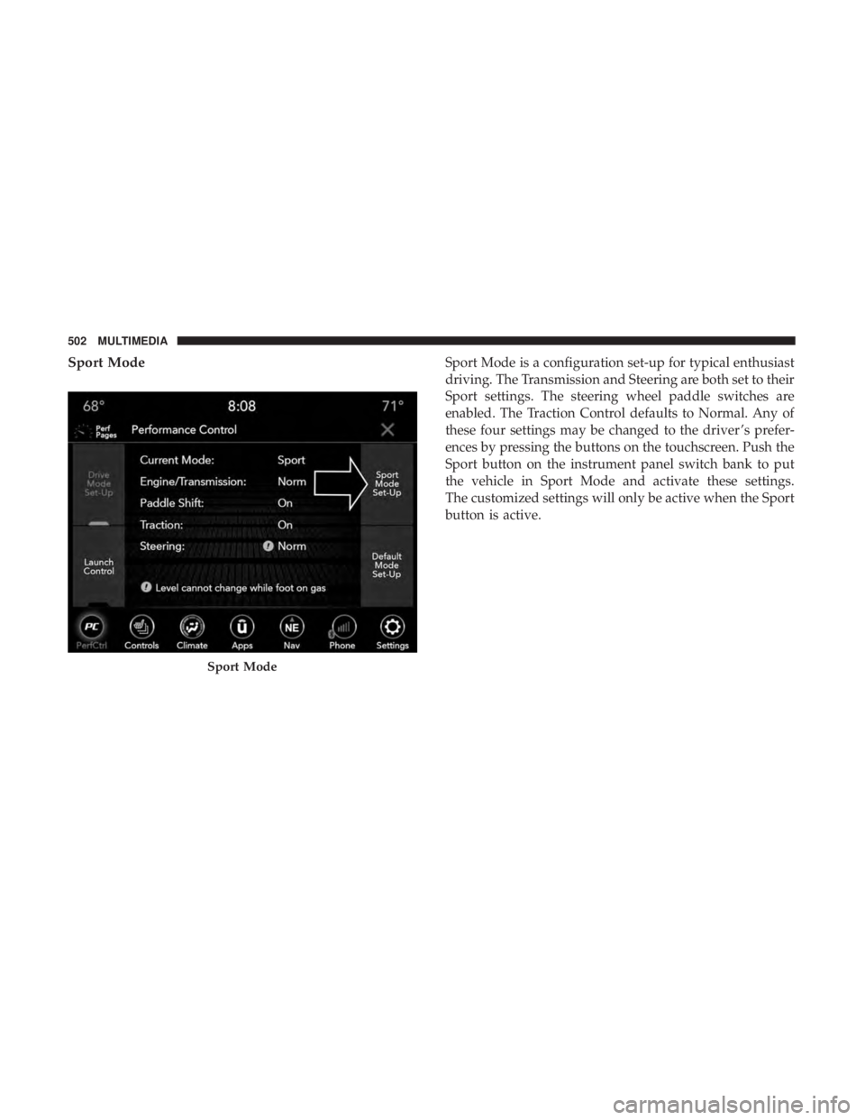
Sport ModeSport Mode is a configuration set-up for typical enthusiast
driving. The Transmission and Steering are both set to their
Sport settings. The steering wheel paddle switches are
enabled. The Traction Control defaults to Normal. Any of
these four settings may be changed to the driver ’s prefer-
ences by pressing the buttons on the touchscreen. Push the
Sport button on the instrument panel switch bank to put
the vehicle in Sport Mode and activate these settings.
The customized settings will only be active when the Sport
button is active.
Sport Mode
502 MULTIMEDIA
Page 548 of 560
HazardDriving Through Flowing, Rising, Or Shallow
Standing Water ......................... .303
Hazard Warning Flashers .....................307
Headlights Automatic ..............................69
Cleaning .............................. .421
High Beam/Low Beam Select Switch ...........67
Lights On Reminder .......................70
On With Wipers ..........................69
Passing ................................68
Switch .................................66
Time Delay ..............................69
Washers .............................. .374
Head Restraints ......................... .56, 57
Head Rests ............................ .56, 57
Heated Mirrors .............................65
Heater, Engine Block ....................... .233
High Beam/Low Beam Select (Dimmer) Switch ......67
Hill Start Assist ........................... .158
Hitches Trailer Towing .......................... .295
Holder, Coin ..............................112
HomeLink (Garage Door Opener) ...............105Hood Prop
.............................. .100
Hood Release ............................ .100
Ignition ..................................27
Switch .................................27
Information Center, Vehicle ...................126
Inside Rearview Mirror ....................62, 307
Instrument Cluster ..................... .122, 125
Descriptions ........................... .146
Display ........................... .126, 129
Instrument Panel Lens Cleaning ................423
Interior Appearance Care .....................422
Interior Lights ..............................71
Intermittent Wipers (Delay Wipers) ...............76
Introduction ................................4
In Vehicle Help Vehicle User Guide ........................17
Jack Location ............................ .326
Jack Operation ........................... .397
Jump Starting ......................... .349, 351
Key
Fob
Arm The System ..........................35
Panic Alarm .............................22
546 INDEX