Page 326 of 560
Cavity Cartridge FuseMini-FuseDescription
49 – –Fuse – Spare
50 – –Fuse – Spare
51 –20 Amp Yellow Front Heated / Vented Seats – If Equipped
52 –10 Amp Red Heated Cupholders/Rear Heated Seat Switches –
If Equipped
53 –10 Amp Red HVAC Module/In Vehicle Temperature Sensor
54 – –Fuse – Spare
55 – –Fuse – Spare
56 – –Fuse – Spare
57 – –Fuse – Spare
58 –10 Amp Red Airbag Module
59 –20 Amp Yellow Adjustable Pedals – Police
60 – –Fuse – Spare
61 – –Fuse – Spare
62 – –Fuse – Spare
63 – –Fuse – Spare
64 –25 Amp Breaker Rear Windows (Charger/300)
65 –10 Amp Red Airbag Module
66 – –Fuse – Spare
67 –10 Amp Red Rain and Light Sensor / Sunroof / Inside RR
324 IN CASE OF EMERGENCY
Page 334 of 560

NOTE:•For vehicles that are equipped, do not attempt to
install a center cap or wheel cover on the compact
spare.
•
Refer to “Tires—General Information” in “Servicing
And Maintenance” for additional warnings, cautions,
and information about the spare tire, its use, and opera-
tion.
8. Install the lug nuts with the cone shaped end of the lug nut toward the wheel. Lightly tighten the lug nuts.
WARNING!
To avoid the risk of forcing the vehicle off the jack, do
not tighten the wheel nuts fully until the vehicle has
been lowered. Failure to follow this warning may
result in serious injury.
9. Lower the vehicle to the ground by turning the jack handle counterclockwise. 10. Finish tightening the lug nuts. Push down on the
wrench while at the end of the handle for increased
leverage. Tighten the lug nuts in a star pattern until
each nut has been tightened twice. Refer to “Torque
Specifications” in “Technical Specifications” for proper
lug nut torque.
11. Stow the wheel chocks, jack, tools and flat tire. Make sure the base of the jack faces the front of the vehicle
before tightening down the fastener.
WARNING!
A loose tire or jack thrown forward in a collision or
hard stop could endanger the occupants of the vehicle.
Always stow the jack parts and the spare tire in the
places provided. Have the deflated (flat) tire repaired
or replaced immediately.
Road Tire Installation
1. Mount the road tire on the axle.
2.
Install the remaining lug nuts with the cone shaped end of
the nut toward the wheel. Lightly tighten the lug nuts.
332 IN CASE OF EMERGENCY
Page 364 of 560

Once A Month Or Before A Long Trip:
•Check engine oil level.
• Check windshield washer fluid level.
• Check tire pressure and look for unusual wear or
damage. Rotate tires at the first sign of irregular wear,
even if it occurs before your next scheduled service.
• Check the fluid levels of the coolant reservoir, brake
master cylinder, and power steering (if equipped) and
fill as needed.
• Check function of all interior and exterior lights.
Maintenance Plan — 3.6L And 5.7L
Required Maintenance Intervals:
Refer to the maintenance schedules on the following page
for the required maintenance intervals.
At Every Oil Change Interval As Indicated By Oil
Change Indicator System:
•Change oil and filter
• Rotate the tires
Rotate at the first sign of irregular wear, even if it
occurs before your next scheduled service
• Inspect battery and clean and tighten terminals as
required
• Inspect brake pads, shoes, rotors, drums, hoses and
park brake
• Inspect engine cooling system protection and hoses
• Inspect exhaust system
• Inspect engine air cleaner if using in dusty or
off-road conditions
362 SERVICING AND MAINTENANCE
Page 368 of 560
At Each Stop For Fuel
•Check the engine oil level. Refer to “Engine Compart-
ment” in this chapter for further information.
• Check the windshield washer solvent and add if re-
quired.
Once A Month
• Check tire pressure and look for unusual wear or
damage.
• Inspect the battery, and clean and tighten the terminals
as required.
• Check the fluid levels of the coolant reservoir, brake
master cylinder, and add as needed.
• Check all lights and other electrical items for correct
operation. At Each Oil Change
•
Change the engine oil filter.
• Inspect the brake hoses and lines.
CAUTION!
Failure to perform the required maintenance items
may result in damage to the vehicle.
366 SERVICING AND MAINTENANCE
Page 395 of 560

•If frequent engine coolant (antifreeze) additions are
required, the cooling system should be pressure tested
for leaks.
•
Maintain engine coolant (antifreeze) concentration at a
minimum of 50% OAT coolant (conforming to MS.90032)
and distilled water for proper corrosion protection of your
engine which contains aluminum components.
• Make sure that the coolant expansion bottle overflow
hoses are not kinked or obstructed.
• Keep the front of the radiator clean. If your vehicle is
equipped with air conditioning, keep the front of the
condenser clean.
• Do not change the thermostat for Summer or Winter
operation. If replacement is ever necessary, install ONLY
the correct type thermostat. Other designs may result in
unsatisfactory engine coolant (antifreeze) performance,
poor gas mileage, and increased emissions.
Brake System
In order to assure brake system performance, all brake
system components should be inspected periodically. Refer
to the “Maintenance Plan” in this section for the proper
maintenance intervals.
WARNING!
Riding the brakes can lead to brake failure and possi-
bly a collision. Driving with your foot resting or riding
on the brake pedal can result in abnormally high brake
temperatures, excessive lining wear, and possible
brake damage. You would not have your full braking
capacity in an emergency.
Fluid Level Check — Brake Master Cylinder
Check the fluid level in the master cylinder immediately if
the brake system warning light indicates system failure.
Check the fluid level in the master cylinder when perform-
ing underhood services.
Clean the top of the master cylinder area before removing
the cap. Add fluid to bring the level up to the top of the
“FULL” mark on the side of the master cylinder reservoir.
Overfilling of fluid is not recommended because it may
cause leaking in the system.
Add enough fluid to bring the level up to the requirements
described on the brake fluid reservoir. With disc brakes,
8
SERVICING AND MAINTENANCE 393
Page 398 of 560

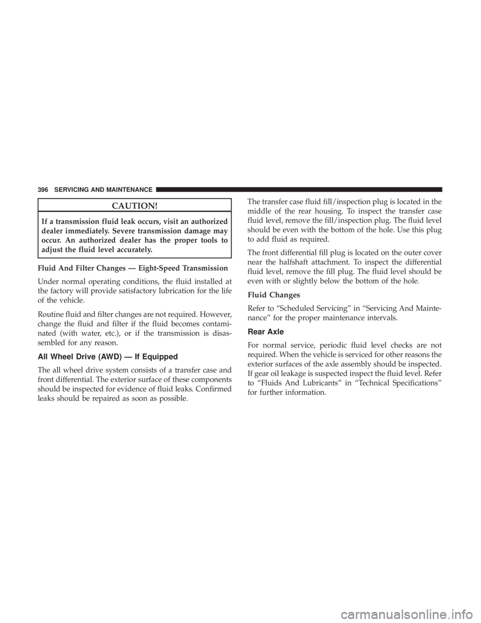
CAUTION!
If a transmission fluid leak occurs, visit an authorized
dealer immediately. Severe transmission damage may
occur. An authorized dealer has the proper tools to
adjust the fluid level accurately.
Fluid And Filter Changes — Eight-Speed Transmission
Under normal operating conditions, the fluid installed at
the factory will provide satisfactory lubrication for the life
of the vehicle.
Routine fluid and filter changes are not required. However,
change the fluid and filter if the fluid becomes contami-
nated (with water, etc.), or if the transmission is disas-
sembled for any reason.
All Wheel Drive (AWD) — If Equipped
The all wheel drive system consists of a transfer case and
front differential. The exterior surface of these components
should be inspected for evidence of fluid leaks. Confirmed
leaks should be repaired as soon as possible. The transfer case fluid fill/inspection plug is located in the
middle of the rear housing. To inspect the transfer case
fluid level, remove the fill/inspection plug. The fluid level
should be even with the bottom of the hole. Use this plug
to add fluid as required.
The front differential fill plug is located on the outer cover
near the halfshaft attachment. To inspect the differential
fluid level, remove the fill plug. The fluid level should be
even with or slightly below the bottom of the hole.
Fluid Changes
Refer to “Scheduled Servicing” in “Servicing And Mainte-
nance” for the proper maintenance intervals.
Rear Axle
For normal service, periodic fluid level checks are not
required. When the vehicle is serviced for other reasons the
exterior surfaces of the axle assembly should be inspected.
If gear oil leakage is suspected inspect the fluid level. Refer
to “Fluids And Lubricants” in “Technical Specifications”
for further information.
396 SERVICING AND MAINTENANCE
Page 400 of 560

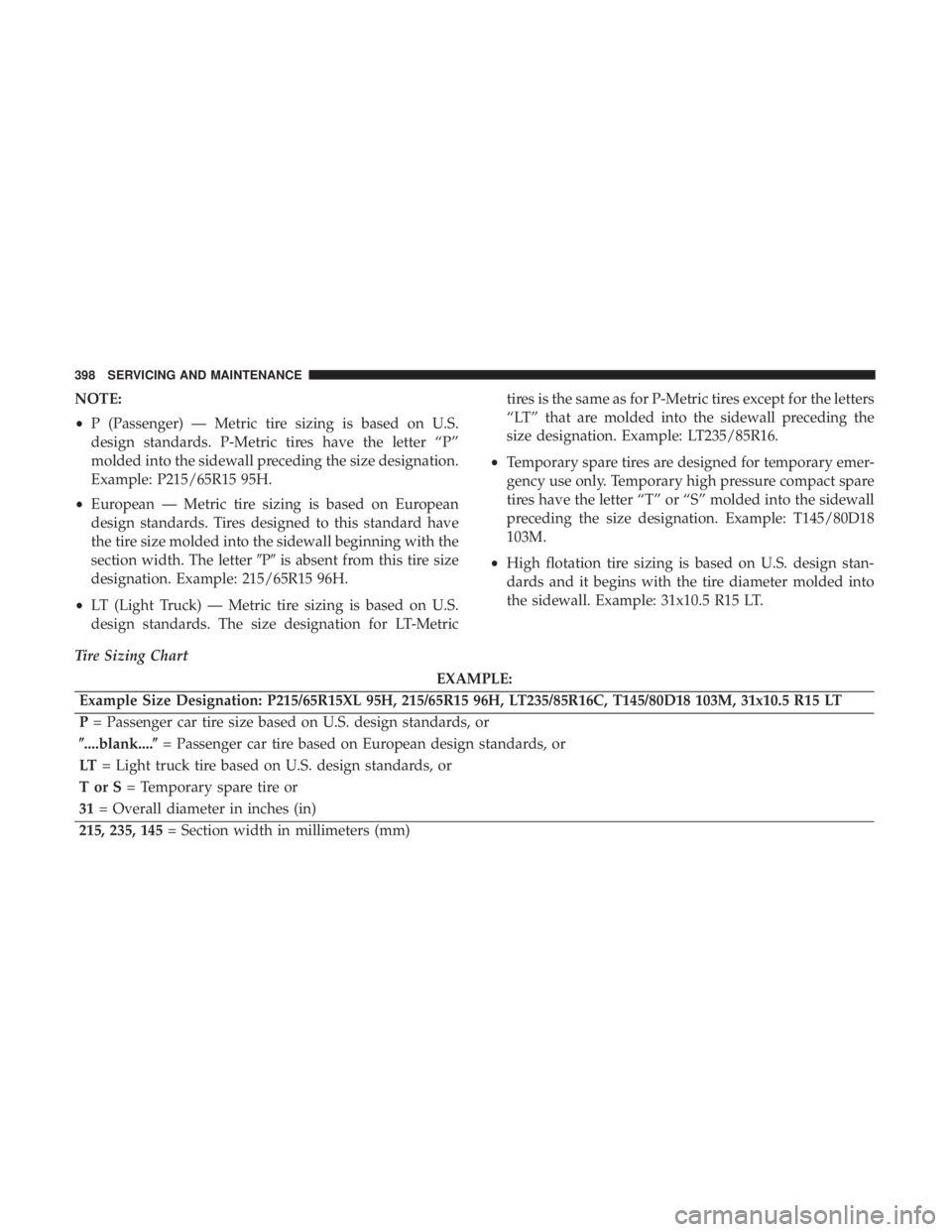
NOTE:
•P (Passenger) — Metric tire sizing is based on U.S.
design standards. P-Metric tires have the letter “P”
molded into the sidewall preceding the size designation.
Example: P215/65R15 95H.
• European — Metric tire sizing is based on European
design standards. Tires designed to this standard have
the tire size molded into the sidewall beginning with the
section width. The letter �P�is absent from this tire size
designation. Example: 215/65R15 96H.
• LT (Light Truck) — Metric tire sizing is based on U.S.
design standards. The size designation for LT-Metric tires is the same as for P-Metric tires except for the letters
“LT” that are molded into the sidewall preceding the
size designation. Example: LT235/85R16.
• Temporary spare tires are designed for temporary emer-
gency use only. Temporary high pressure compact spare
tires have the letter “T” or “S” molded into the sidewall
preceding the size designation. Example: T145/80D18
103M.
• High flotation tire sizing is based on U.S. design stan-
dards and it begins with the tire diameter molded into
the sidewall. Example: 31x10.5 R15 LT.
Tire Sizing Chart
EXAMPLE:
Example Size Designation: P215/65R15XL 95H, 215/65R15 96H, LT235/85R16C, T145/80D18 103M, 31x10.5 R15 LT
P = Passenger car tire size based on U.S. design standards, or
�....blank....� = Passenger car tire based on European design standards, or
LT = Light truck tire based on U.S. design standards, or
TorS= Temporary spare tire or
31 = Overall diameter in inches (in)
215, 235, 145 = Section width in millimeters (mm)
398 SERVICING AND MAINTENANCE
Page 401 of 560

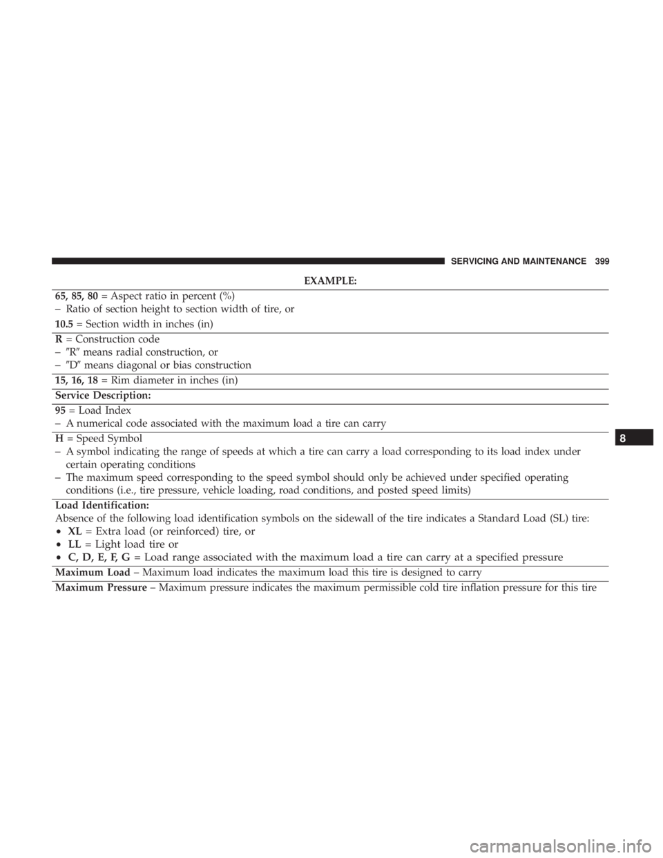
EXAMPLE:
65, 85, 80 = Aspect ratio in percent (%)
–Ratio of section height to section width of tire, or
10.5 = Section width in inches (in)
R = Construction code
–�R� means radial construction, or
–�D� means diagonal or bias construction
15, 16, 18 = Rim diameter in inches (in)
Service Description:
95 = Load Index
–A numerical code associated with the maximum load a tire can carry
H = Speed Symbol
–A symbol indicating the range of speeds at which a tire can carry a load corresponding to its load index under
certain operating conditions
–The maximum speed corresponding to the speed symbol should only be achieved under specified operating
conditions (i.e., tire pressure, vehicle loading, road conditions, and posted speed limits)
Load Identification:
Absence of the following load identification symbols on the sidewall of the tire indicates a Standard Load (SL) tire:
• XL = Extra load (or reinforced) tire, or
• LL = Light load tire or
• C, D, E, F, G = Load range associated with the maximum load a tire can carry at a specified pressure
Maximum Load – Maximum load indicates the maximum load this tire is designed to carry
Maximum Pressure – Maximum pressure indicates the maximum permissible cold tire inflation pressure for this tire
8
SERVICING AND MAINTENANCE 399