Page 260 of 532
WARNING ALERTS
Rear
Distance (in/cm) Greater
than
79 inches (200 cm) 79-59 inches
(200-150 cm) 59-47 inches
(150-120 cm) 47-39 inches
(120-100 cm) 39-25 inches
(100-65 cm) 25-12 inches
(65-30 cm) Less than
12 inches (30 cm)
Audible Alert
Chime None Single 1/2-
SecondTone
(for rear
center only) Slow
(for rear
center only) Slow
(for rear
center only) Fast
(for rear
center only) Fast Continuous
Arc — Left Rear None None None None None 2nd Flash-
ing1st Flashing
Arc — Cen- ter Rear None 6th Solid 5th Solid 4th Solid 3rd Flash-
ing2nd Flash-
ing 1st Flashing
Arc — Right Rear None None None None None 2nd Flash-
ing1st Flashing
Radio
Volume
Reduced No
Yes YesYesYesYes Yes
258 STARTING AND OPERATING
Page 262 of 532

Cleaning The ParkSense System
Clean the Rear Park Assist sensors with water, car wash
soap and a soft cloth. Do not use rough or hard cloths. In
washing stations, clean sensors quickly keeping the vapor
jet/high pressure washing nozzles at least 4 inches (10 cm)
from the sensors. Do not scratch or poke the sensors.
Otherwise, you could damage the sensors.
ParkSense System Usage Precautions
NOTE:
•Ensure that the rear bumper is free of snow, ice, mud,
dirt and debris to keep the ParkSense system operating
properly.
• Jackhammers, large trucks, and other vibrations could
affect the performance of ParkSense or render the sys-
tem temporarily unavailable.
• When you turn ParkSense off in DRIVE, the instrument
cluster will display �PARKSENSE OFF� for five seconds.
Furthermore, once you turn ParkSense off, it remains off
until you turn it on again, even if you cycle the ignition. •
When you move the gear selector to the REVERSE
position and ParkSense is turned off, the instrument
cluster display will show the “PARKSENSE OFF” mes-
sage for as long as the vehicle is in REVERSE.
• ParkSense will reduce the volume of the radio when it is
sounding an audio tone.
• Clean the ParkSense sensors regularly, taking care not to
scratch or damage them. The sensors must not be
covered with ice, snow, slush, mud, dirt or debris.
Failure to do so can result in the system not working
properly. The ParkSense system might not detect an
obstacle behind the fascia/bumper, or it could provide a
false indication that an obstacle is behind the fascia/
bumper.
• Ensure the ParkSense system is off if objects such as
bicycle carriers, trailer hitches, etc., are placed within 12
inches (30 cm) from the rear fascia/bumper. Failure to
do so can result in the system misinterpreting a close
object as a sensor problem, causing the “PARKSENSE
UNAVAILABLE SERVICE REQUIRED” message to be
shown in the instrument cluster display.
260 STARTING AND OPERATING
Page 283 of 532

HAZARD WARNING FLASHERS
The Hazard Warning flasher switch is located on the
instrument panel, below the radio.Push the switch to turn on the Hazard Warning
flasher. When the switch is activated, all direc-
tional turn signals will flash on and off to warn
oncoming traffic of an emergency. Push the
switch a second time to turn off the Hazard Warning
flashers.
This is an emergency warning system and it should not be
used when the vehicle is in motion. Use it when your
vehicle is disabled and it is creating a safety hazard for
other motorists.
When you must leave the vehicle to seek assistance, the
Hazard Warning flashers will continue to operate even
though the ignition is placed in the OFF position.
NOTE: With extended use, the Hazard Warning flashers
may wear down your battery.
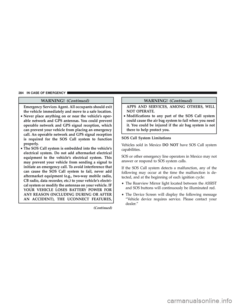
ASSIST AND SOS MIRROR — IF EQUIPPED
If equipped, the rearview mirror contains an ASSIST and a
SOS button.
WARNING!
ALWAYS obey traffic laws and pay attention to the
road. ALWAYS drive safely with your hands on the
(Continued)
Assist And SOS Mirror
7
IN CASE OF EMERGENCY 281
Page 286 of 532

WARNING!(Continued)
Emergency Services Agent. All occupants should exit
the vehicle immediately and move to a safe location.
• Never place anything on or near the vehicle’s oper-
able network and GPS antennas. You could prevent
operable network and GPS signal reception, which
can prevent your vehicle from placing an emergency
call. An operable network and GPS signal reception
is required for the SOS Call system to function
properly.
• The SOS Call system is embedded into the vehicle’s
electrical system. Do not add aftermarket electrical
equipment to the vehicle’s electrical system. This
may prevent your vehicle from sending a signal to
initiate an emergency call. To avoid interference that
can cause the SOS Call system to fail, never add
aftermarket equipment (e.g., two-way mobile radio,
CB radio, data recorder, etc.) to your vehicle’s electri-
cal system or modify the antennas on your vehicle. IF
YOUR VEHICLE LOSES BATTERY POWER FOR
ANY REASON (INCLUDING DURING OR AFTER
AN ACCIDENT), THE UCONNECT FEATURES,
(Continued)
WARNING! (Continued)
APPS AND SERVICES, AMONG OTHERS, WILL
NOT OPERATE.
• Modifications to any part of the SOS Call system
could cause the air bag system to fail when you need
it. You could be injured if the air bag system is not
there to help protect you.
SOS Call System Limitations
Vehicles sold in Mexico DO NOThave SOS Call system
capabilities.
SOS or other emergency line operators in Mexico may not
answer or respond to SOS system calls.
If the SOS Call system detects a malfunction, any of the
following may occur at the time the malfunction is de-
tected, and at the beginning of each ignition cycle:
• The Rearview Mirror light located between the ASSIST
and SOS buttons will continuously be illuminated red.
• The Device Screen will display the following message
“Vehicle device requires service. Please contact your
dealer.”
284 IN CASE OF EMERGENCY
Page 300 of 532
CavityCartridge Fuse Mini-FuseDescription
(300) – If Equipped
34 – 10 Amp RedSteering Column Module/Clock
(300)
35 – 5 Amp TanBattery Sensor
36 – 15 Amp BlueElectronic Exhaust Valve – If
Equipped
37 – 20 Amp YellowRadio
38 – 20 Amp YellowPower Outlet Inside Arm Rest/
Console Media Hub
40 30 Amp Pink –Fuel Pump (6.2L SRT HO – If
Equipped)
41 30 Amp Pink –Fuel Pump (6.2L SRT HO – If
Equipped)
42 30 Amp Pink –Rear Defrost
43 – 20 Amp YellowComfort Seat And Steering
Wheel Module (Heated Steering
Wheel/RR Heated Seats)
44 – 10 Amp RedPark Assist / Blind Spot / Rear
View Camera
298 IN CASE OF EMERGENCY
Page 327 of 532

NOTE:When using a portable battery booster pack, follow
the manufacturer’s operating instructions and precautions.
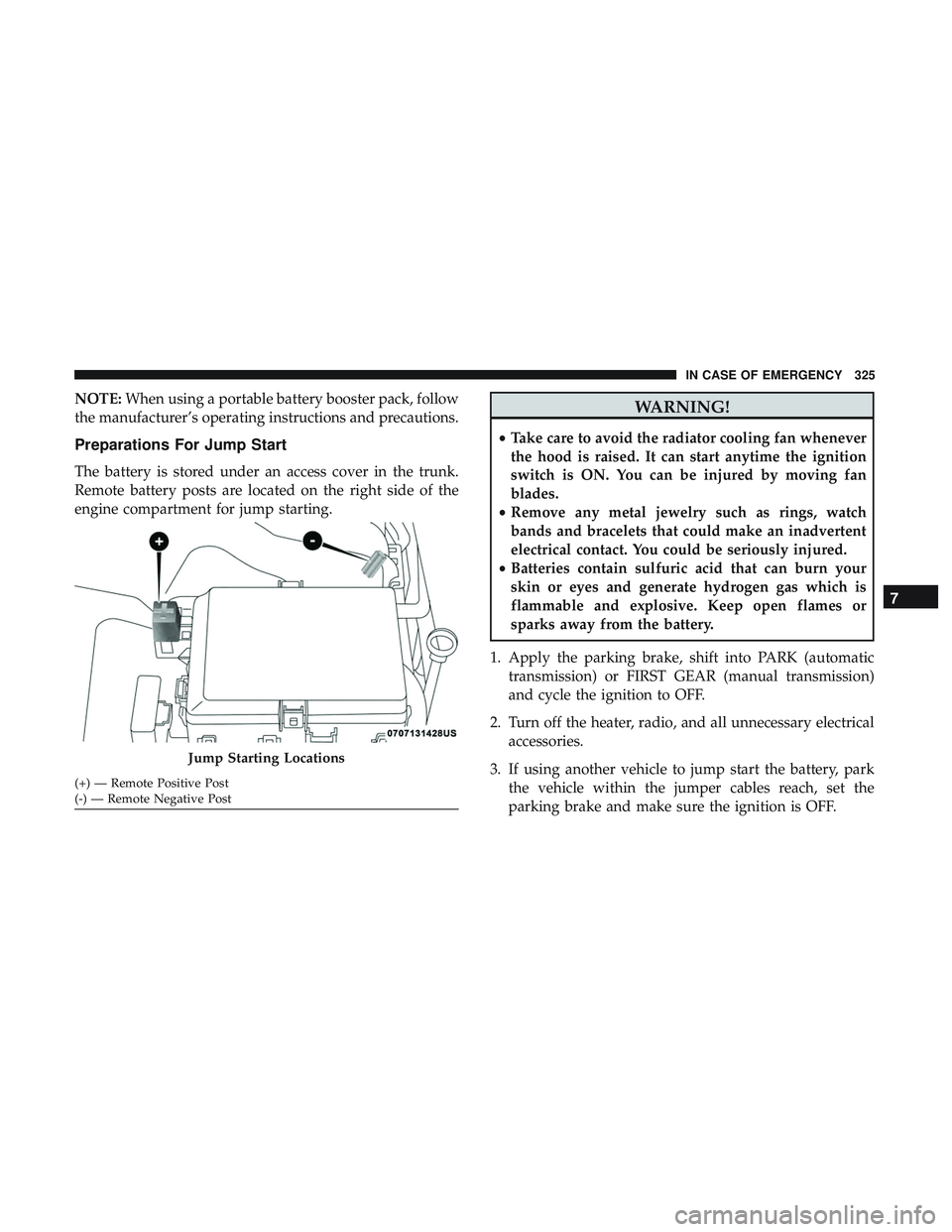
Preparations For Jump Start
The battery is stored under an access cover in the trunk.
Remote battery posts are located on the right side of the
engine compartment for jump starting.
WARNING!
• Take care to avoid the radiator cooling fan whenever
the hood is raised. It can start anytime the ignition
switch is ON. You can be injured by moving fan
blades.
• Remove any metal jewelry such as rings, watch
bands and bracelets that could make an inadvertent
electrical contact. You could be seriously injured.
• Batteries contain sulfuric acid that can burn your
skin or eyes and generate hydrogen gas which is
flammable and explosive. Keep open flames or
sparks away from the battery.
1. Apply the parking brake, shift into PARK (automatic transmission) or FIRST GEAR (manual transmission)
and cycle the ignition to OFF.
2. Turn off the heater, radio, and all unnecessary electrical accessories.
3. If using another vehicle to jump start the battery, park the vehicle within the jumper cables reach, set the
parking brake and make sure the ignition is OFF.
Jump Starting Locations
(+) — Remote Positive Post
(-) — Remote Negative Post
7
IN CASE OF EMERGENCY 325
Page 403 of 532

NOTE:If equipped with light colored leather, it tends to
show any foreign material, dirt, and fabric dye transfer
more so than darker colors. The leather is designed for easy
cleaning, and FCA recommends Mopar total care leather
cleaner applied on a cloth to clean the leather seats as
needed.
CAUTION!
Do not use Alcohol and Alcohol-based and/or Ketone
based cleaning products to clean leather upholstery, as
damage to the upholstery may result.
Glass Surfaces
All glass surfaces should be cleaned on a regular basis with
Mopar Glass Cleaner, or any commercial household-type
glass cleaner. Never use an abrasive type cleaner. Use
caution when cleaning the inside rear window equipped
with electric defrosters or windows equipped with radio
antennas. Do not use scrapers or other sharp instruments
that may scratch the elements.
When cleaning the rear view mirror, spray cleaner on the
towel or cloth that you are using. Do not spray cleaner
directly on the mirror.
8
SERVICING AND MAINTENANCE 401
Page 419 of 532

MULTIMEDIA
CONTENTS
�UCONNECT SYSTEMS ...................419
� DRAG & DROP MENU BAR ................419
� CYBERSECURITY ...................... .420
� UCONNECT SETTINGS ...................421
▫ Customer Programmable Features —
Uconnect 4 Settings .....................422
▫ Customer Programmable Features —
Uconnect 4C/4C NAV Settings .............443
▫ Performance Pages — If Equipped ...........463
▫ Performance Control — If Equipped .........473
� STEERING WHEEL AUDIO CONTROLS —
IF EQUIPPED ......................... .482
▫ Radio Operation ....................... .482
▫ Media Mode ......................... .482
� IPOD/USB/MP3 CONTROL — IF EQUIPPED . . .483 �
RADIO OPERATION AND MOBILE PHONES . . .483
▫ Regulatory And Safety Information ..........483
� UCONNECT VOICE RECOGNITION QUICK
TIPS ................................ .485
▫ Introducing Uconnect ....................485
▫ Get Started .......................... .486
▫ Basic Voice Commands ...................487
▫ Radio .............................. .487
▫ Media .............................. .488
▫ Phone .............................. .490
▫ Voice Text Reply — If Equipped ............491
▫ Climate ............................. .492
▫ Navigation (4C NAV) ....................494
▫ SiriusXM Guardian (4C/4C NAV) —
If Equipped .......................... .495
10