Page 56 of 532

WARNING!(Continued)
•All occupants, including the driver, should not oper-
ate a vehicle or sit in a vehicle’s seat if the head
restraints are not in place of their proper positions in
order to minimize the risk of neck injury in the event
of a crash.
• Head restraints should never be adjusted while the
vehicle is in motion. Driving a vehicle with the head
restraints improperly adjusted or removed could
cause serious injury or death in the event of a
collision.
STEERING WHEEL
Manual Tilt/Telescoping Steering Column —
If Equipped
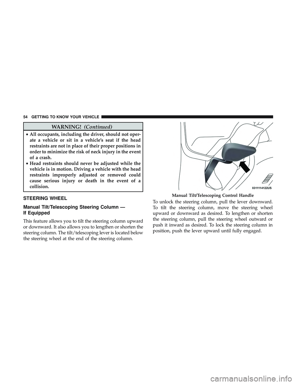
This feature allows you to tilt the steering column upward
or downward. It also allows you to lengthen or shorten the
steering column. The tilt/telescoping lever is located below
the steering wheel at the end of the steering column. To unlock the steering column, pull the lever downward.
To tilt the steering column, move the steering wheel
upward or downward as desired. To lengthen or shorten
the steering column, pull the steering wheel outward or
push it inward as desired. To lock the steering column in
position, push the lever upward until fully engaged.
Manual Tilt/Telescoping Control Handle
54 GETTING TO KNOW YOUR VEHICLE
Page 57 of 532

WARNING!
Do not adjust the steering column while driving.
Adjusting the steering column while driving or driv-
ing with the steering column unlocked, could cause the
driver to lose control of the vehicle. Failure to follow
this warning may result in serious injury or death.
Power Tilt/Telescoping Steering Column —
If Equipped
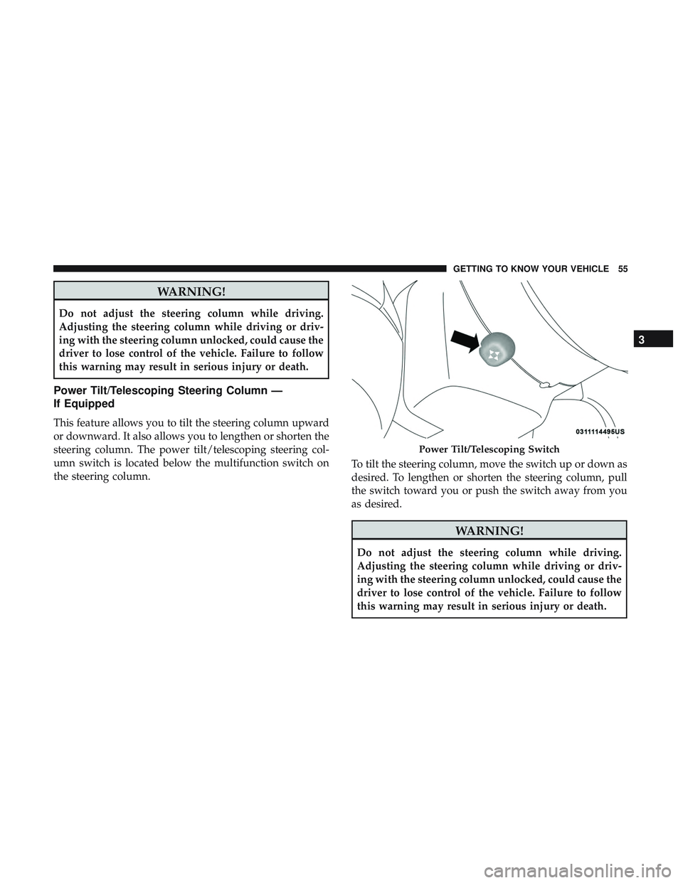
This feature allows you to tilt the steering column upward
or downward. It also allows you to lengthen or shorten the
steering column. The power tilt/telescoping steering col-
umn switch is located below the multifunction switch on
the steering column.To tilt the steering column, move the switch up or down as
desired. To lengthen or shorten the steering column, pull
the switch toward you or push the switch away from you
as desired.
WARNING!
Do not adjust the steering column while driving.
Adjusting the steering column while driving or driv-
ing with the steering column unlocked, could cause the
driver to lose control of the vehicle. Failure to follow
this warning may result in serious injury or death.
Power Tilt/Telescoping Switch
3
GETTING TO KNOW YOUR VEHICLE 55
Page 100 of 532

CAUTION!
•Many accessories that can be plugged in draw power
from the vehicle’s battery, even when not in use (i.e.,
cellular phones, etc.). Eventually, if plugged in long
enough, the vehicle’s battery will discharge suffi-
ciently to degrade battery life and/or prevent the
engine from starting.
• Accessories that draw higher power (i.e., coolers,
vacuum cleaners, lights, etc.), will degrade the bat-
tery even more quickly. Only use these intermit-
tently and with greater caution.
• After the use of high power draw accessories, or long
periods of the vehicle not being started (with acces-
sories still plugged in), the vehicle must be driven a
sufficient length of time to allow the alternator to
recharge the vehicle’s battery.
• Power outlets are designed for accessory plugs only.
Do not hang any type of accessory or accessory
bracket from the plug. Improper use of the power
outlet can cause damage.
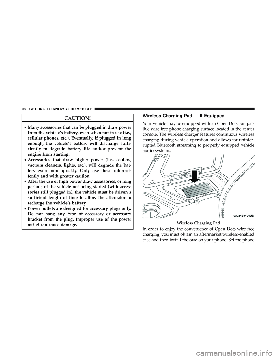
Wireless Charging Pad — If Equipped
Your vehicle may be equipped with an Open Dots compat-
ible wire-free phone charging surface located in the center
console. The wireless charger features continuous wireless
charging during vehicle operation and allows for uninter-
rupted Bluetooth streaming to properly equipped vehicle
audio systems.
In order to enjoy the convenience of Open Dots wire-free
charging, you must obtain an aftermarket wireless-enabled
case and then install the case on your phone. Set the phone
Wireless Charging Pad
98 GETTING TO KNOW YOUR VEHICLE
Page 142 of 532

When the vehicle is started, the BSM warning light will
momentarily illuminate in both outside rear view mirrors
to let the driver know that the system is operational.
Automatic Transmission Vehicles
The BSM system sensors operate when the vehicle is in any
forward gear or REVERSE.
Manual Transmission Vehicles
The BSM system sensors operate when the vehicle is in any
gear.The BSM detection zone covers approximately one lane
width on both sides of the vehicle 12 ft (3.8 m). The zone
length starts at the outside rear view mirror and extends
approximately 10 ft (3 m) beyond the rear bumper of the
vehicle. The BSM system monitors the detection zones on
both sides of the vehicle when the vehicle speed reaches
approximately 6 mph (10 km/h) or higher and will alert
the driver of vehicles in these areas.
NOTE:
•
The BSM system does NOT alert the driver about
rapidly approaching vehicles that are outside the detec-
tion zones.
• The BSM system detection zone DOES NOT change if
your vehicle is towing a trailer. Therefore, visually verify
the adjacent lane is clear for both your vehicle and trailer
before making a lane change. If the trailer or other object
(i.e., bicycle, sports equipment) extends beyond the side
of your vehicle, this may result in the BSM warning light
remaining illuminated the entire time the vehicle is in a
forward gear.
• The BSM system may experience drop outs (blinking on
and off) of the side mirror Warning Indicator lamps
BSM Warning Light
140 SAFETY
Page 356 of 532

To do this, you will need follow the procedure below:
1. Remove the four nuts with the Shaker tool located inglove compartment.
2. Lift off the upper scoop.
NOTE: Be sure to clean off all debris around or inside for
the shaker assembly.
3. Locate the oil fill cover in base assembly to expose the oil fill cap.
4. Remove oil fill cap to add oil.
5. Re-install shaker assembly.
Shaker Hood Air Filter Cleaning
1. Remove the air filter from the intake and set the filter clamp a side.
2. Measure the length of the filter media.
3. Fill a bucket with warm clean water to the depth matching the filter media measurement and add a mild
household detergent or air filter cleaning solution.
4. Without allowing the solution to flow back into the inside of the air filter, submerge the filter media in to the
water and let it soak for ten minutes. 5. Empty the bucket filled with dirty water and repeat
steps 3 and 4.
6. Refill the bucket with clean warm water and rinse the filter by rotating the filter.
NOTE: The water should be clean with no signs of dirt in
the bucket.
7. Allow the filter to air dry. Re-install the filter on the intake system once it is dry.
Shaker Hood Removal And Cleaning
1. Remove the four nuts with the Shaker tool located in glove compartment.
2. Lift off the upper scoop.
NOTE: Be sure to clean off all debris around or inside for
the shaker assembly.
3. Using a water and mild detergent clean the following locations.
— The water drain slot located at the front forward edge of
the shaker assembly.
— The seals attached to the scoop and air box.
354 SERVICING AND MAINTENANCE
Page 427 of 532
Units
After pressing the “Units” button on the touchscreen you
may select each unit of measure independently displayed
in the instrument cluster display, and navigation system (if
equipped). The following selectable units of measure are
listed below:
Setting NameSelectable Options
Units US Metric Custom
Speed MPH km/h
Distance mi km
Fuel Consumption MPG (US)MPG (UK) L/100 km km/L
Pressure psikPa bar
Temperature °F °C
Voice
After pressing the “Voice” button on the touchscreen, the
following settings will be available:
Setting Name Selectable Options
Voice Response Length BriefDetailed
Show Command List AlwaysWith Help Never
10
MULTIMEDIA 425
Page 449 of 532
Voice
After pressing the “Voice” button on the touchscreen, the
following settings will be available:
Setting NameSelectable Options
Voice Response Length Brief Detailed
Show Command List Neverw/Help Always
Clock & Date
After pressing the “Clock & Date” button on the touch-
screen, the following settings will be available:
Setting Name Selectable Options
Sync Time With GPS — If Equipped On
Off
NOTE:
The “Sync Time With GPS” feature will allow you to automatically have the radio set the time. Set Time Hours +–
Set Time Minutes +–
Time Format 12 hrs24 hrs
AM PM
10
MULTIMEDIA 447